Networking & Content Delivery
Building highly resilient applications using Amazon Route 53 Application Recovery Controller, Part 1: Single-Region stack
This is the first of a two-part blog post series that shows how the recently launched Amazon Route 53 Application Recovery Controller (Route 53 ARC) service allows you to centrally coordinate failovers and recovery readiness of your application. Using Route 53 ARC with a sample single-Region and multi-Region infrastructure stack, this post provides guidance for planning and implementing a resiliency strategy for your environment.
As a part of the shared responsibility model for resiliency between you (the customer) and AWS, AWS handles the resiliency of the global infrastructure that runs all of the services offered in the AWS cloud. Your responsibility for resiliency is determined by the AWS services that you select.
For example, if you use Amazon Elastic Compute Cloud (Amazon EC2) instances, you are responsible for the resiliency of the instances. This means that you should deploy them to multiple locations such as AWS Availability Zones (AZs), an AWS Auto Scaling group (ASG) to implement self-healing, and a load balancer to distribute incoming traffic across those Availability Zones’ EC2 instances. (For more information, see Use Fault Isolation to Protect Your Workload.) On the other hand, if you use a service such as Amazon S3, since AWS operates the infrastructure layer for the service, the operating system, and the platforms, you are only responsible for managing resiliency of your data (that is, data backup, versioning, and replication strategies).
Although you are responsible for resiliency for some services, AWS regularly adds services and features that make it easier for you to fulfill your part of the shared responsibility model. Route 53 ARC is a new addition to the toolkit. Its features enable you to continually monitor your application’s ability to recover from failures, and to control application recovery across multiple AWS Regions, AZs, and on premises. Route 53 ARC’s capabilities make application recovery simpler and more reliable by eliminating manual steps required by traditional tools and processes.
It’s helpful when you read this post if you have a fundamental understanding of Route 53 ARC’s capabilities and components. We recommend first taking a look at the Application Recovery Controller components and their relationships, as we reference them throughout this post.
Cell-based architecture
Using a cell-based architecture helps you to compartmentalize issues so that your application is more resilient. As Werner Vogels says in one of his All Things Distributed blog posts:
“[E]verything fails all the time. Components fail and fail often, in large systems. Entire instances fail. Network failures can isolate significant chunks of infrastructure. Less often, an entire data center can become isolated or go down due to a natural disaster. At AWS, we engineer for failure, and we rely on cell-based architecture to combat issues before they happen.”
Cells are instantiations of a service that are isolated from each other. To maximize resiliency, you should partition your application into isolated cells, so that when one cell fails, that failure can’t affect the other cells. Partitioning your application means also partitioning network and compute infrastructure across cells, as well as ensuring that cross-cell dependencies are managed by Regional AWS services. When you make operational changes and code deployments, you should change only one cell at a time, within the cell boundaries. This isolates deployment failures to a specific cell, which can help prevent correlated failures, that is, failures caused by the same issue in multiple cells. When you limit potential failures to just one cell, you limit the scope and magnitude of failures when they occur, and you may be able to mitigate the failure by simply removing the impaired cell from service.
When you build your application stack using cell-based design concepts, you benefit from a small and well-defined blast radius. Using cell partitioning also provides the benefit of a strong isolation boundary. When one specific cell is impaired, it’s clear where the failure is located and you can route your users away from the problem area. The features in Route 53 ARC align with and support the benefits of using cell-based design. In fact, a fundamental component that you create in Route 53 ARC is called a cell. Each cell in Route 53 ARC defines an independent unit of failover for your application.
With this basic understanding of the benefits of cells and cell-based design, let’s look at a sample single-Region stack that we can set up and use with the Route 53 ARC features.
Sample single-Region infrastructure stack
Many customers operate highly-available stacks in a single-Region by using a standard multi-AZ setup, in which their infrastructure components run across multiple AZs, attached to a load balancer to distribute incoming traffic across the AZs. For a use case that requires extreme reliability and availability, customers might also require additional logical isolation, where the change control mechanisms to these cells are also isolated from each other to ensure that operator errors don’t take down the entire stack.
A sample representation of such a use case is shown in Figure 1, where extreme reliability and availability is required: a fictitious stack that we’ll use with Route 53 ARC features. We’ll use an AZ-aligned cell boundary for the application layer, with a dedicated Network Load Balancer (NLB) for each cell.

The following describes the architecture of the application:
- The application is deployed in a single AWS Region in three AZs. Within each AZ, a replica of the application runs independently. Each replica runs on a set of EC2-based servers that are in an ASG, fronted by an NLB. There are three of these replicas, each isolated in an AZ. This isolates the impact if there’s a faulty deployment rolled out, such as if the listener configuration is accidentally changed to an incorrect port. A multi-AZ NLB would provide the same level of NLB service availability that a per-replica NLB does, but we’ve introduced this additional isolation in the application layer to further protect from potential operator errors.
- Each NLB has a unique DNS name, which is the entry point to each application replica. Amazon Route 53 hosts a DNS hosted zone for the domain, which we’ve configured with a record that has a weighted routing policy pointing to the three NLBs. We’ve set the weights for all three records to the same value, so that each replica receives about the same amount of user traffic during normal operation.
- All three application replicas access one Amazon Aurora database cluster. The cluster has one writer node and two reader nodes, which are all deployed across the three AZs. Amazon Aurora is a managed AWS service built on a cell-based architecture behind the scenes, and is fault tolerant by design. The cluster volume spans multiple AZs in a single Region, and each AZ contains a copy of the cluster volume data. This functionality means that the database (DB) cluster can tolerate a failure of an AZ with no data loss and only a brief interruption of service. To learn more, see Amazon Aurora ascendant: How we designed a cloud-native relational database.
We’ve provided a CloudFormation template (infra-stack) that you can use to deploy this single-Region stack in your account. You can use the template to create the stack, and then follow along with this post as we set up Route 53 ARC structures with the sample stack. The CloudFormation template deploys the application components as individual cells, with independent parameters, based on a common template. We recommend this approach to ensure that your application is deployed to each cell with the same configuration, while also allowing you to make changes to parameters for each cell, for example, Auto Scaling group parameters. To create greater isolation, you could deploy a unique template per cell or build stage gates into your CI/CD processes between cells in a deployment.
The Route 53 ARC features and components that we discuss throughout this post are also available to deploy in your account by using a second CloudFormation template (arc-stack). For setup instructions, see the readme file that comes with the template.
Stack readiness
You likely have monitoring in place to tell you about the health of the stacks in each of your AZs, in general. It’s also important to know if each stack replica has the same configuration setup and the same runtime state. Route 53 ARC’s Readiness checks can monitor your replicas to provide exactly this information. Let’s see how to use this feature with our single-Region stack.
Set up readiness checks
The first step in using readiness checks is to create a recovery group to represent your application. A recovery group includes cells for each individual failure-containment unit, or replica, of your application, such a stack in an AZ. Next, you create resource sets (collections of similar resources) for each resource type in your application (NLBs, ASGs, and so on), and associate a readiness check with each resource set. Finally, you associate each resource with a readiness scope: a cell or a recovery group. Then Route 53 ARC runs readiness checks and you can view the readiness status. The readiness check configuration in Route 53 ARC for our single-Region application with the recovery group and cells is outlined in Figure 2. In this configuration, we have one recovery group with one cell that represents the entire Region’s stack. We’ll call this the Regional cell.
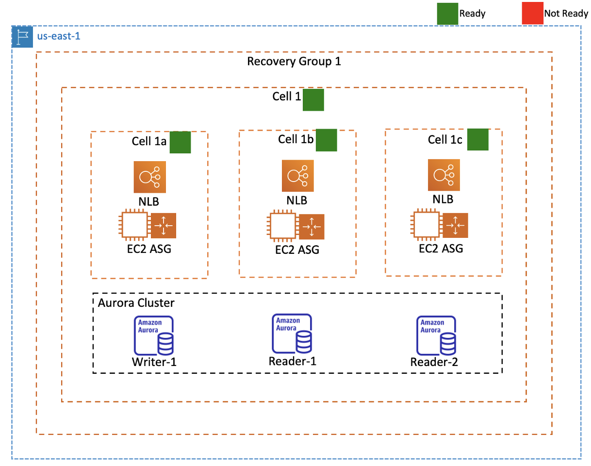
In this Regional cell, we have three nested cells, which represent the replicas in each AZ. We’ll call these the zonal cells. We create readiness checks for resource sets to monitor each type of AWS resource in our stack (NLB, ASG, and Aurora DB Cluster) by providing the Amazon Resource Names (ARNs) of the resources. We also associate each ARN with the related readiness scope (cell) of that resource.
After we’ve set up readiness checks, Route 53 ARC continuously evaluates the corresponding readiness rules for each resource type with the resources deployed in the cells. The readiness status is Ready or Not ready. There are different readiness statuses that you can view, such as cell status, resource set status, and recovery group status.
For example, in Figure 3, you can see the statuses for the Regional cell and the zonal cells, as well as the statuses for each resource set. Each cell has evaluated to Ready because the configurations are the same (for example, the ASG’s minimum and maximum values) and the runtime states align (for example, the number of healthy targets behind the NLB load balancers) across the cells. Note that readiness checks make sure that your configured Auto Scaling group quotas across cells are consistent. If there is a mismatch, Route 53 ARC raises the quota for the resource with the lower quota. However, for capacity, readiness checks do not decide on your behalf on what the capacity of your cells should be. You should understand your application requirements to size your ASG with enough buffer capacity in each cell to manage if another cell is unavailable.
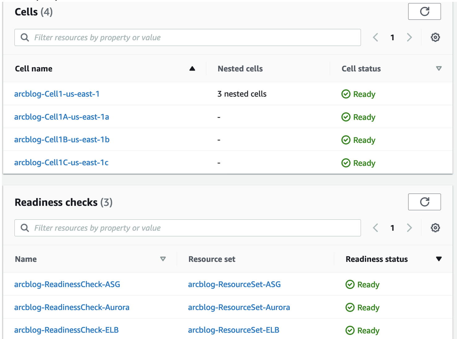
Figure 3: Route 53 ARC console showing readiness checks for single-Region stack
Readiness scenario
Now that we’ve set up readiness checks for our example single-Region stack, let’s consider a scenario where we’re rolling out a new version of an Auto Scaling group configuration and changing the group’s minimum and maximum values to handle an expected increase in traffic for the application.
We’ll take advantage of our cell-based setup and deploy the new configuration first to just one cell, Cell 1a. As soon as we deploy the change to Cell 1a, the Route 53 ARC console shows that the Regional cell (arcblog-Cell1-us-east-1) and the three zonal cells are all Not ready, as you can see in Figure 4. In addition, the resource set for the Auto Scaling groups is Not ready.
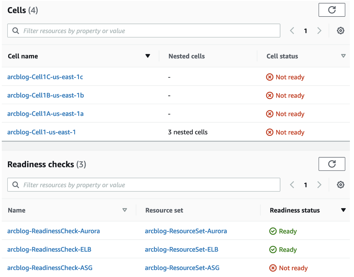
Let’s dive deeper into what’s happening here. Route 53 ARC has a number of readiness rules for each resource set that it uses to evaluate readiness, depending on the resource type. The Auto Scaling group readiness check shows as Not ready because there’s a difference between Auto Scaling groups’ minimum and maximum instances and in the Auto Scaling groups’ deployed capacity between the cells in the configuration.
In addition, the readiness status for every cell is Not ready, even though we only modified the configuration for Cell 1a. When you change only one resource in a resource set, the effect on the readiness status of the other resources (and therefore of the readiness status of the other cells) depends on the specific rule checks on the condition of the resource that you changed. In this case, the rule inspects all Auto Scaling groups to make sure that they have the same capacity. If any one of them does not, they are all set to Not ready. And since an Auto Scaling group in each cell is Not ready, the readiness check cell summary shows all the cells as Not ready.
Also, since we’ve set up Cell 1a, Cell 1b, and Cell 1c as nested cells under Cell 1, a zonal cell status being Not Ready means that the overall Regional cell status is set to Not ready. This provides a broader and faster view of the overall “drift” between the replicas in your application, and makes it easier to drill down to specific resources to address issues.
You should proactively monitor readiness checks so that you’re aware of drift between cells. Route 53 ARC emits ReadinessChecks metric to CloudWatch indicating the number of readiness checks in each state (Ready, Not Ready, Not Authorized, Unknown). CloudWatch Alarms can be configured at an account level to track the number of readiness checks in each state and issue alerts via Simple Notification Service (SNS) when thresholds are breached. We recommend that you treat readiness checks as a supplement to your application and infrastructure monitoring or health checker systems. You should make decisions about whether to fail away from or to a cell based on your monitoring and health check systems, and consider readiness checks as a complementary service to those systems. Route 53 ARC readiness checks also support Amazon EventBridge integration so that you can set up event-driven rules that monitor your resources and initiate actions, such as sending email notifications about readiness check status changes.
Next, let’s see how to use Route 53 ARC’s highly available routing controls to route users away from an unhealthy cell and toward just healthy cells during a failure scenario.
Failure scenario
Consider a simple failure scenario where your monitoring systems have detected that users of this single-Region application stack are randomly observing errors. When you troubleshoot further, you learn the following details:
- The application stack in AZ 1a is returning 5xx errors for 7% of the API calls
- The load balancer health checks in the AZ are failing intermittently but not consistently
- The EC2 instances in AZ 1a are being randomly replaced by your Auto Scaling group with no identifiable pattern.
As a Site Reliability Engineer for this environment, when you see random, intermittent failures like this where your overall stack is in a partially degraded state, your first recovery question is likely: “How can I safely send my users to only healthy replicas and not to a replica that is impaired and not ready to serve traffic?”
Let’s see how Route 53 ARC can help you answer that question.
How can I route users to healthy cells?
For our failure scenario, the ideal user experience we’d like to achieve is one of the following outcomes:
- If there’s an issue with a specific zonal cell within the Region, then route users away from that cell
- If there’s an issue with all three zonal cells in the Region, then route the user’s request to a static maintenance page
We can use Route 53 ARC to implement a solution to manage routing for this scenario. There are three components in Route 53 ARC that work together to redirect traffic flow: Route 53 ARC routing controls, Route 53 health checks, and Route 53 record sets.
Routing controls are simple ON/OFF switches, hosted on the highly resilient Route 53 ARC data plane, which is integrated with the Route 53 health check data plane. Routing control health checks are associated with Route 53 DNS records that front application replicas.

In practice, when you turn off a routing control, Route 53 marks the associated health check as unhealthy. When the health check is unhealthy, Route 53 doesn’t include the DNS record associated with it in DNS query responses. Because both Route 53 ARC and Route 53 data planes are highly available, routing controls are a robust mechanism to change a Route 53 health check status manually and drive failover in failure scenarios.
You create routing controls and other Route 53 ARC recovery resources by calling control plane API operations. To get or update routing control states, you access one of Route 53 ARC’s five Regional endpoints with data plane API operations. Routing control states are accessible through five redundant cluster endpoints, hosted on five AWS Regions. You can view or modify the state of a routing control during outages using any of the five endpoints, when an automation or script might not be able to reach one specific endpoint.
Important: When you change the states of routing controls, make sure that your code has logic to retry each Regional endpoint in sequence, for higher resiliency and availability. We also recommend that you store in advance a list of all the relevant resource ARNs and URLs that you need, such as routing control ARNs and Regional endpoints URLs. During a failover event, you shouldn’t rely on calling any control plane API operations. Instead, you should depend only on accessing the five highly available endpoints for data plane operations.
Set up for routing controls
To use Route 53 ARC to route users in the failure scenario shared earlier, we’ll use the following setup, created by the CloudFormation stack. Our example has four routing controls, which are outlined in Figure 6. We create one routing control that we’ll use for the Regional cell (Routing Control 1) and one for each of the three zonal cells (AZs) (Routing Control 1a, Routing Control 1b, and Routing Control 1c).
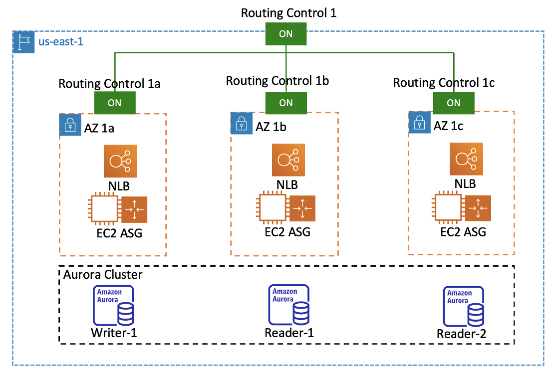
A Route 53 ARC console view of the routing controls that our CloudFormation stack created is shown in Figure 7. All the routing control states are set to ON initially, so user traffic is distributed equally across the cells.
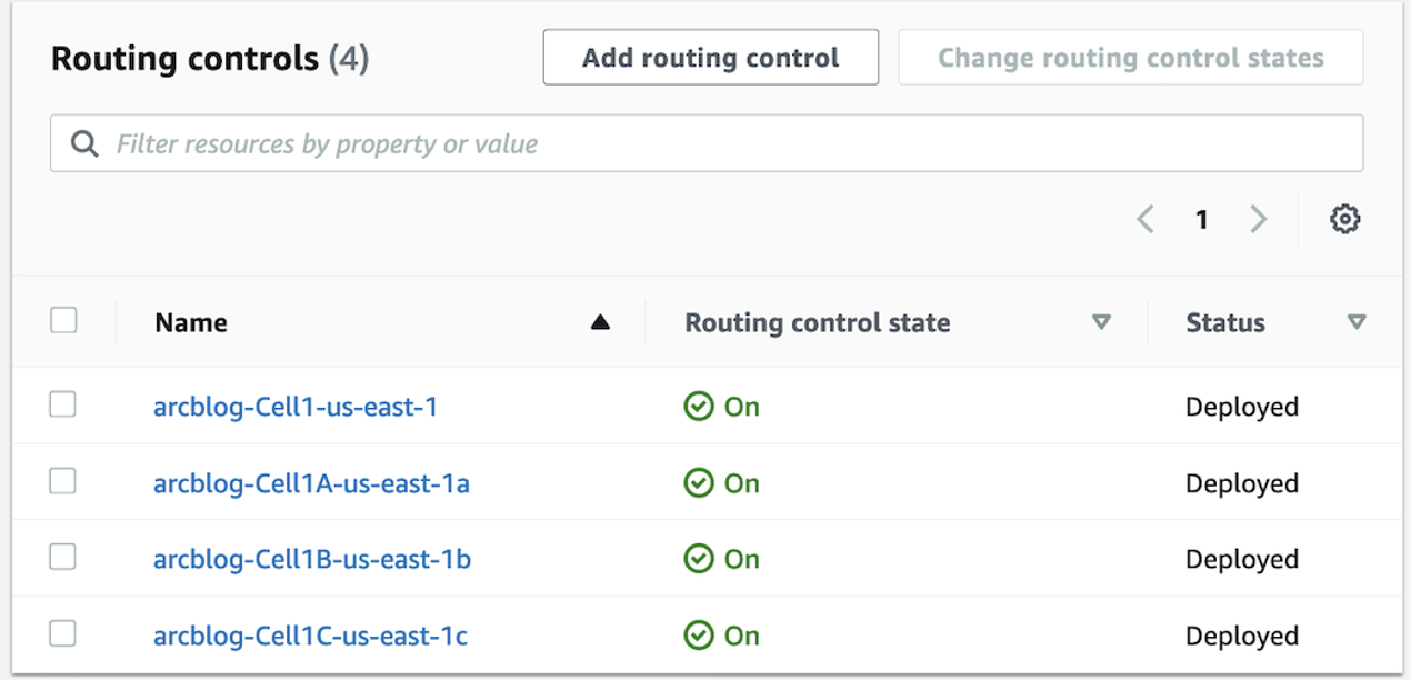
Each routing control has a corresponding Route 53 routing control health check, that is, a health check with a state that is explicitly controlled by one of the routing controls we created. To simplify the notation in the following example, let’s call the Regional cell routing control’s health check HC1 and the zonal cells’ routing controls’ health checks HC1a, HC1b, and HC1c, respectively.
Let’s look at a setup of the Route 53 DNS records for our example routing controls and health checks. Say that we have a DNS hosted zone called arcblog.aws (this could be any existing domain name that the application uses).
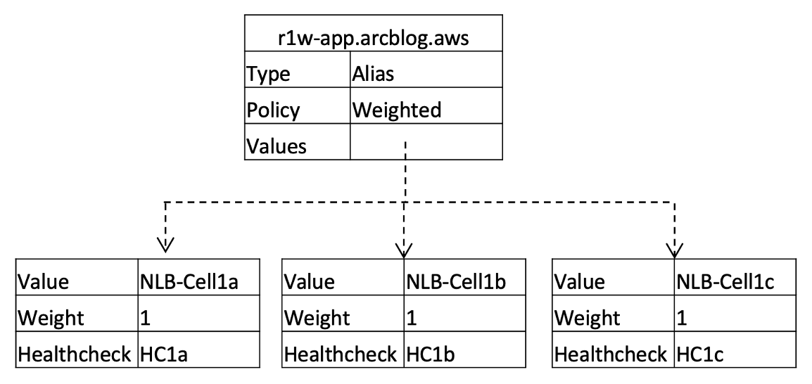
First, we create a DNS record, r1w-app.arcblog.aws, with three weighted records to directly front the three zonal cells. The record is configured as follows:
- The DNS record has a weighted routing policy, with an Alias record pointing to each zonal cell’s NLB.
- The weight is 1 for all these records so that there’s an even distribution of traffic.
- Each of the weighted records is associated with a corresponding routing control health check for the cell, so we can bring the cell in and out of service with the associated routing control.
- In addition, because the Alias records are associated with the cells’ NLBs and we’ve set ‘Evaluate target health’ to TRUE, Route 53 will automatically withdraw the NLB targets from service if they become unhealthy.
The weighted DNS record configuration for the zonal cells is shown in the following diagram:
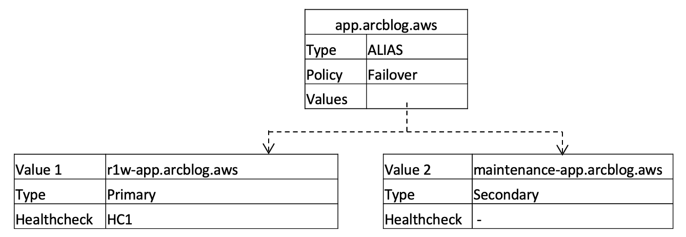
Next, we create a DNS record, app.arcblog.aws, that our users will use to access our application. The record is configured as follows:
- The record is configured as an Alias record with a failover routing policy, where r1w-app.arcblog.aws is the primary record, and maintenance.arcblog.aws record is the secondary record.
- The primary record is associated with the HC1 health check directly. If HC1 is unhealthy, the maintenance record takes effect and directs users away from the application stack to a static maintenance page location. This could be, for example, a static page hosted on an Amazon S3 bucket.
The top-level DNS record configuration for app.arcblog.aws is shown in the following diagram:
As mentioned before, all the Route 53ARC features we discuss in this post are available for you to deploy in your account by using a CloudFormation template (arc-stack).
Status dashboard
To help you explore how Route 53 ARC routing control works, we’ve built a tiny AWS Lambda-based status dashboard app to display the live state of the infra stack as you change routing control states. The Lambda function simply performs regular DNS queries for the app.arcblog.aws domain, and checks the IP address in the response against active NLB IP addresses, to determine which AZ the NLB is running in. Depending on the IP address that’s returned, it does one of the following:
- If the NLB IP address is in one of the AZs, it lists the NLB IP address under the AZ name (for example, us-east-1a under us-east-1a).
- If the NLB IP address doesn’t belong to one of the AZs, it lists the address under Maintenance, since the address must be the maintenance page.
When all the routing control states are set to ON, the dashboard app, as shown in Figure 10, displays just about an even split for the number of responses provided. The view is in descending order (see the Timestamp column), with the latest response at the top.

You can deploy this dashboard app by using the third CloudFormation template (lambda-stack). We deployed the Lambda function in the same Amazon Virtual Private Cloud (VPC) as the single-Region stack so that it resolves the private hosted zone for arcblog.aws locally. It’s fronted by a public Application Load Balancer (ALB) that is set up as a part of the template so that you can access the dashboard from your local machine.
Routing control during failure scenario
Let’s see how the Route 53 ARC structures that we’ve created help us to achieve the two user experiences that we set out to address at the start of this section.
- If there’s an issue with a specific zonal cell within the Region, then route users away from that cell.
To achieve this, we simply set the state for Routing Control 1a to OFF, as shown in Figure 11. This causes Route 53 to set the associated HC1a health check to unhealthy, so the Alias for NLB-Cell1a is not included in responses to DNS queries for the r1w-app.arcblog.aws record. Now users are not routed to the zonal cell of us-east-1a.

The dashboard app, as shown in Figure 12, doesn’t list any IP addresses under us-east-1a after you turn OFF the routing control.

- If there’s an issue with all three zonal cells in the Region, then route the user’s request to a static maintenance page.
With our Route 53 ARC routing control setup, achieving this is straightforward. Routing Control 1 manages user traffic to the three zonal cells, so when we turn that off, as shown in Figure 13, all three cells no longer receive user traffic. As soon as we turn off Routing Control 1, Route 53 sets the associated health check, HC1, to unhealthy. This takes app.arcblog.aws’s primary record (r1w-app.arcblog.aws) out of service, and resolves the secondary failover record (maintenance.arcblog.aws) instead.
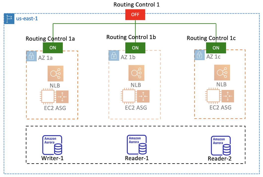
As expected, when we set Routing Control 1 to OFF, the dashboard app, as shown in Figure 14, stops resolving any of the zonal cells’ NLB IP addresses in the VPC and lists the app under Maintenance, which means that users are being routed to the maintenance page.

The dashboard app helps us to clearly understand the correlation between the Route 53 ARC routing controls and the single-Region stack that we’re using as an example. To track routing control for your own application with Route 53 ARC setup and configuration, you can modify the logic of the Lambda function, or replace it with your own advanced monitoring systems
Note: It’s possible to use routing controls to drive non-DNS based failover actions by creating some additional automation. For example, you could deploy an AWS Lambda function that runs on an Amazon CloudWatch Events Schedule and queries the routing control data plane for the status of relevant routing controls and then performs actions. We’ll go into details about this in Part 2 of the blog post where we’ll discuss using routing controls to fail over a database’s primary writer to a standby Region during a Regional failover event.
Failing over safely
When you’re working with several routing controls at the same time, you might set up and operate routing control states in ways that could accidentally lead to unintended consequences.
For example, in our single-Region setup, a potential scenario could arise when you intend to route users to a maintenance page when every cell is having issues. However, you might inadvertently turn off all of the zonal cells’ routing controls instead of turning off the Regional cell’s routing control. This would cause Route 53 to fail open and load balance traffic across all zonal cells’ NLBs, which wouldn’t be the desired behavior. To help prevent inadvertent errors like this, you can use the Route 53 ARC safety rules feature.
There are two types of safety rules in Route 53 ARC: assertion rules and gating rules. With an assertion rule, when you change a routing control state or set of routing control states, Route 53 ARC enforces that the criteria you set when you configured the rule is met, otherwise the routing control states aren’t changed. With a gating rule, you can enforce an overall “on/off switch” over a set of routing controls, so that whether those routing control states can be changed is enforced based on a set of criteria that you specify in the rule.
A safety rule that would prevent the undesired fail open scenario here would be the following:
| Rule Type |
Asserted Control |
Config Type |
Threshold |
Inverted? |
| Assertion |
Routing Control 1a, 1b, 1c |
Atleast |
2 |
FALSE |
This rule asserts that, of the three zonal cells’ routing controls, at least two must be in the ON state. Put another way, no more than one zonal cell’s routing control can be in the OFF state at the same time. This is to ensure that there is always enough capacity available to handle user requests, assuming an N+1 style deployment. You can still fail over the whole application to the maintenance page by turning OFF the Regional cell’s routing control. This assertion rule is created as a part of the second CloudFormation template (arc-stack).
Cleanup
If you used the CloudFormation templates that we provided to create AWS resources to follow along with this blog post, we recommend that you delete them now to avoid future recurring charges.
Conclusion
Building robust failover and recovery mechanisms requires extensive planning, testing, and tooling. In this post, using a simple single-Region stack as a sample, we outlined how Route 53 ARC’s centralized readiness checks, routing controls, and safety rules can help you coordinate failover and readiness to build strongly resilient applications.
In Part 2 of this blog post, we’ll expand the scope of our stack to another Region and see how Route 53 ARC complements multi-Region failover processes.
Related information
- Building highly resilient applications using Amazon Route 53 Application Recovery Controller, Part 2: Multi-Region stack
- Introducing Amazon Route 53 Application Recovery Controller
- Creating Disaster Recovery Mechanisms Using Amazon Route 53
About the Authors

Harsha W Sharma
Harsha W Sharma is a Principal Solutions Architect with AWS in New York. Harsha joined AWS in 2016 and works with Global Financial Services customers to design and develop architectures on AWS, and support their journey on the cloud.

Gerrard Cowburn
Gerrard Cowburn is a Solutions Architect with AWS based in London. Gerrard supports Global Financial Services customers in greenfield and migration based architectural deep dives and prototyping activities. In his free time, Gerrard enjoys exploring the world through food and drink, road trips, and track days.

Shiv Bhatt
Shiv Bhatt is a Global Account Solutions Architect at AWS helping customers in their journey to the cloud. He is passionate about helping customers build well-architected solutions and innovate in their space.