Migration & Modernization
Enhancing Amazon Elastic VMware Service – Deploying the NSX Edge Cluster through SDDC Manager for Application Virtual Networks
When deploying Amazon Elastic VMware Service (EVS), the NSX Edge Cluster deploys independently of the Software Defined Data Center (SDDC) Manager, preventing access to Application Virtual Networks for optional VMware Cloud Foundation (VCF) tools such as VCF Logs, VCF Operations and VCF Automation. This post outlines a solution enabling Application Virtual Networks by deploying an NSX Edge cluster through the SDDC Manager API.
Solution Overview
This solution allows you to redeploy the NSX Edge cluster via the SDDC Manager API. There will be an interruption to north/south traffic during the implementation of this solution. To reduce any potential impact on workloads running in your EVS environment, we recommend performing these actions immediately after your initial deployment of EVS, or during a maintenance window.
Figure 1 below shows how the route server is architected for a default EVS deployment
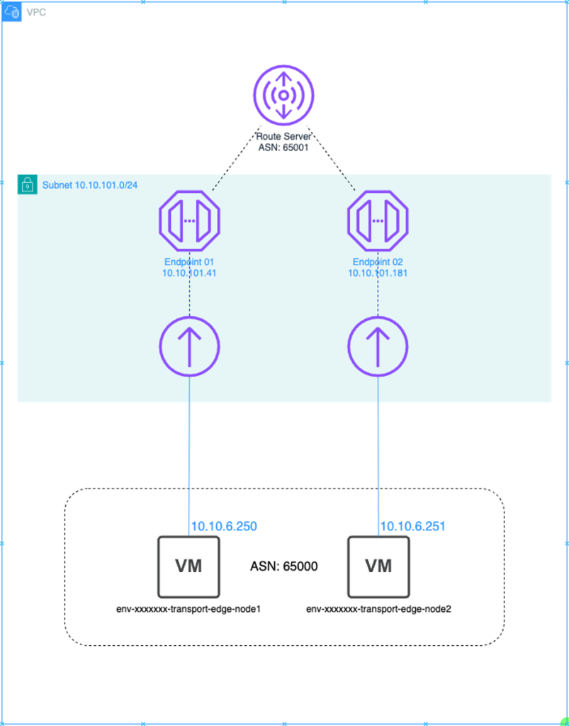
Figure 1: Default Route Server and NSX Edge Deployment
Understanding the Challenge
The standard EVS deployment process deploys the uplink NSX Edges independent of the SDDC Manager. When the NSX Edge Cluster is not deployed via this process, SDDC Manager does not have the ability to create “Application Virtualization Networks”, which are required to deploy other VCF capabilities such as VCF Automation and Operations. While these tools can still be deployed outside of SDDC manager, this can increase operational overhead and architectural complexity, which can be simplified by deploying a new NSX Edge Cluster via the SDDC manager API. This approach provides flexibility to define BGP pairings between NSX and Virtual Private Cloud (VPC) Route Server endpoints. SDDC Manager requires redundant uplinks for the NSX edges it manages, in separate subnets to their Border Gateway Protocol (BGP) peers. To accomplish this requirement, we will deploy additional route server peers in a new private VPC subnet and configure the NSX Edges with an additional IP Address in one of the EVS Expansion VLANs.
Prerequisites
- Amazon EVS Environment Deployed
- AWS Identity and Access Management (IAM) permissions for VPC Route Server
- Administrator access to vCenter
- Administrator access to NSX-T
- Access to the SDDC Manager APIs
- Create two new DNS entries with both forward and reverse lookup entries for the new edge virtual machines
Creating an Additional Route Server Endpoint & peers
As part of deploying the new NSX edge cluster, SDDC Manager will deploy two new edge virtual machines. Each edge virtual machine requires two uplinks, and each uplink must be in a different subnet. Therefore, before deploying the new NSX Edge Cluster, you need to create an additional private subnet as well as an additional route server endpoint and peers in the Amazon EVS VPC.
Prior to creating the new route server endpoint and peers, the existing second endpoint and its associated peer must be deleted. To accomplish this, perform the following steps:
1. Create an additional private subnet within the EVS VPC, match your subnet size to the existing private subnet
- After logging into your AWS account, navigate to the VPC console and select Subnets on the left
- Select Create subnet
- Select your EVS VPC from the drop-down
- Enter a name for the new subnet
- Select the availability zone. Verify that this is the same availability zone as the service access subnet
- Select the VPC CIDR that the subnet CIDR will come from
- Enter the CIDR of the new subnet
- Select Create subnet at the bottom of the screen
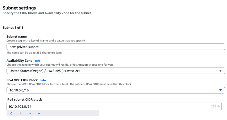
Figure 2: Create subnet settings
2. Attach the new subnet to the private route table configured for EVS
- For traffic to be able to flow to/from this subnet it needs to be explicitly attached to the private route table
- From the VPC console, select subnets on the left
- Select the new subnet that was created in step 1, then select Route table and then Edit route table association
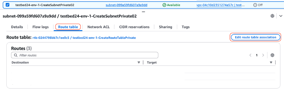
Figure 3: Route table settings
- Select the private route table from the drop-down list and then choose Save
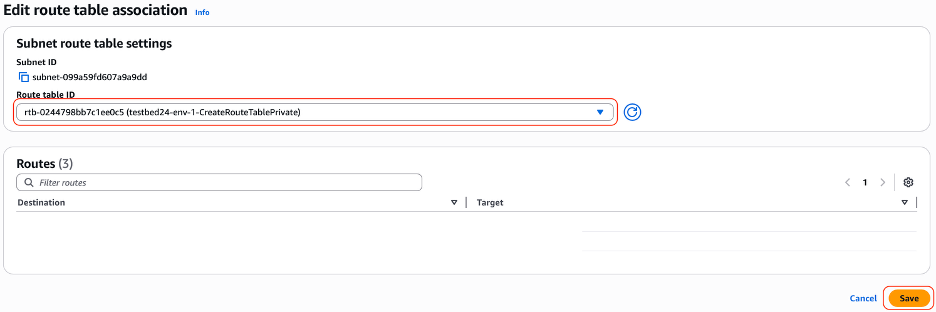
Figure 4: Route table association
3. Shut down the existing edge nodes via vCenter. AWS EVS supports only one edge cluster, so you need to shut down the existing edges to avoid any issues.
** At this point, there will be an outage of all north - south traffic. The outage will conclude after BGP has been configured on the new Edge Cluster **
- Log into the EVS deployed vCenter
- Select the first EVS deployed edge node, right click and select Power then Shut down guest OS
- Repeat the process with the second EVS deployed edge node
4. Remove the second route server peer that was created during the EVS Deployment
- Navigate to the VPC console and then select Route servers on the left
- Select Route server peers then select the second peer, then select Actions and Delete route server peer
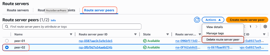
Figure 5: Route Server Console
5. Remove the second route server endpoint that was created during the EVS Deployment
- Select Route server endpoints then select the second endpoint, then select Actions and Delete route server endpoint
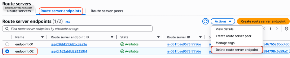
Figure 6: Route Server Endpoint Console
- Wait for the state to change to Deleted before continuing
6. Create an additional route server peer on the first route server endpoint
- This route server peer will talk to the second edge node in the new edge cluster
- Select Route server peers then Create route server peer
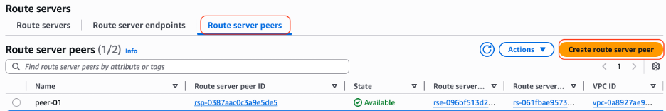
Figure 7: Route Server Peer Console
- Give the new peer a name
- From the drop-down select endpoint-01
- Enter the IP address that will be its BGP peer
- Enter the NSX Edge Cluster ASN
- Verify BGP Keepalive is selected
- Select Create route server peer at the bottom of the screen
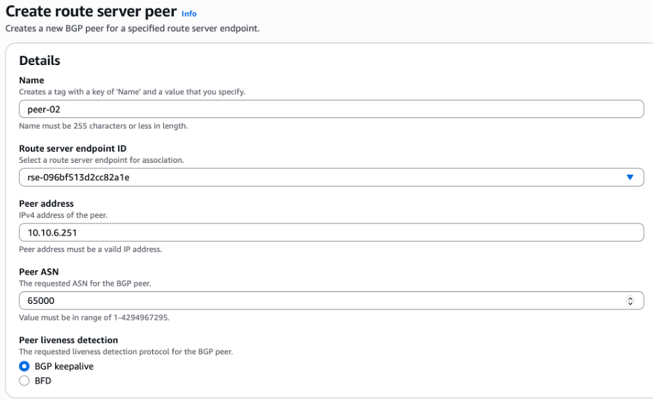
Figure 8: Adding a Route Server PeerCreate a new route server endpoint in the new private subnet created in step 1
7. Create a new route server endpoint in the new private subnet created in step 1
- Next you need to create a new Route server endpoint in the new subnet that we created in step 1
- Navigate to the VPC console and then select Route servers on the left
- Select Route server endpoints then Create route server endpoint
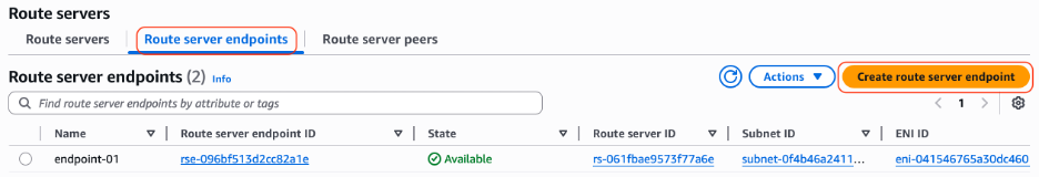
Figure 9: Route Server Endpoint Console
- Enter the name for the new endpoint
- Select the Route server from the drop-down list
- Select the new private subnet created in step 1 from the drop-down list
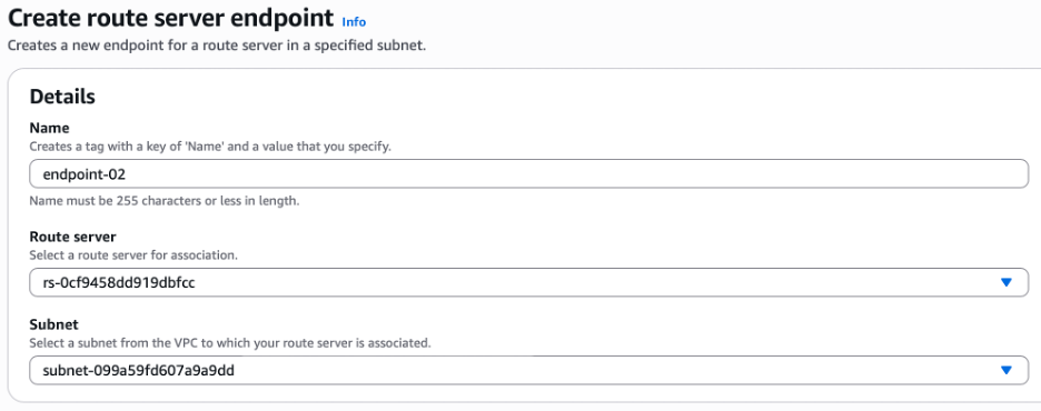
Figure 10: Adding a Route Server Endpoint
8. Create two new route server peers on the new route server endpoint, by following the steps below.
- Now that there is a new Endpoint in our second private subnet, you need to create two route server peers. These peers define the BGP partners of the endpoint, which in this case, will be the new edge nodes that will be created
- Navigate to the VPC console and then select Route servers on the left
- Select Route server peers then Create route server peer
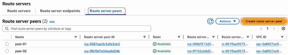
Figure 11: Route Server Console
- Give the new peer a name
- From the drop-down select endpoint-02
- Enter the IP address that will be its BGP peer
- Enter the NSX Edge Cluster ASN
- Verify BGP Keepalive is selected
- Select ‘Create route server peer’ at the bottom of the screen
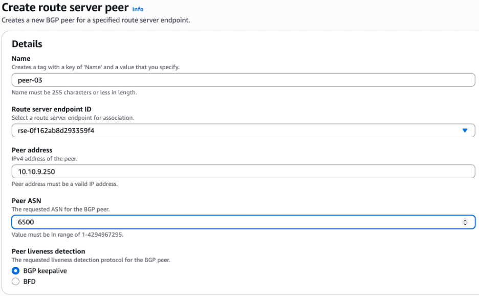
Figure 12: Adding a Route Server Peer
- Repeat steps 8c to 8i to create a second Route server peer on Endpoint 02
Figure 13 below shows what the new route server architecture will look like
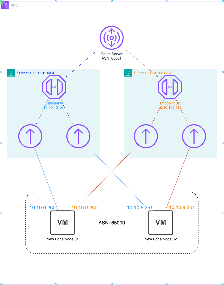
Figure 13: New EVS Route server configuration
Before creating the new edge cluster, you need to get the ID of the compute cluster.
The ID of the compute cluster is required for the JSON file that you will use to create the edge cluster. To get the ID you will need to use the API_Explorer included in the SDDC Manager interface. Follow the steps below to get the compute cluster ID.
- Navigate to the SDDC Manager API Explorer: https://<sddc_manager.mydomain.tld>/ui/sddc-manager/developer-center/api-explorer
- Scroll down and expand the Clusters section
- Expand GET /v1/clusters
- Scroll down and select Execute
- Select the cluster name and then scroll down to the “id” field
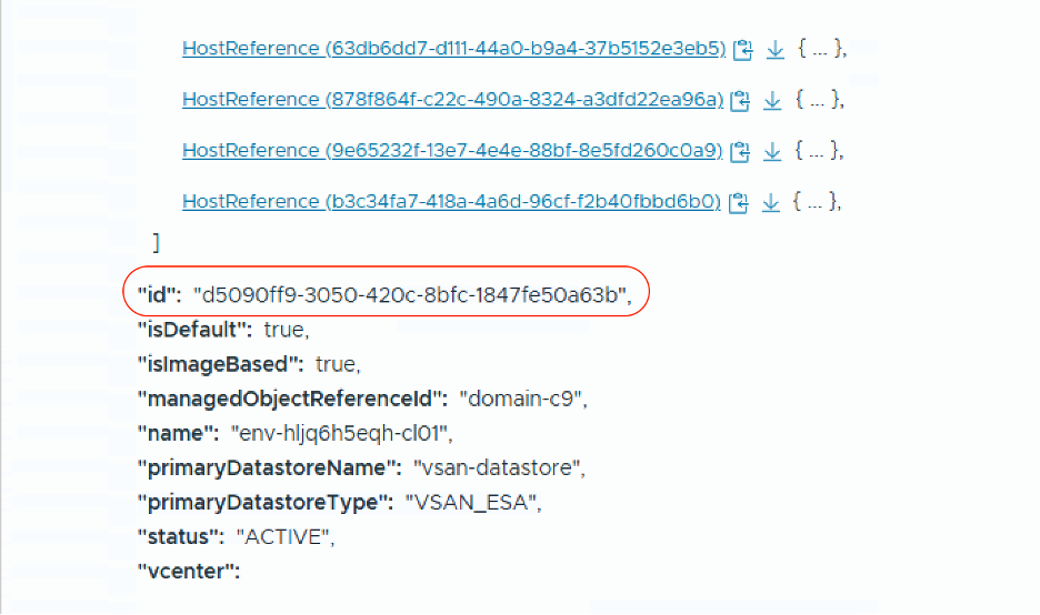
Figure 14: SDDC Manager API Get Cluster Response
Next, use the JSON file which will be posted to the SDDC Manager API to create a new NSX Edge Cluster. Requirements for this JSON
- New NSX Edge Cluster Name
- Forward and Reverse DNS entries for each new NSX Edge node to be deployed
- IP Addresses for each new Edge Virtual Machine
- Management IP for each new Edge VM on the VM Mgmt VLAN (VLAN 20)
- Two new TEP IP addresses for each edge vm on the Edge TEP VLAN (VLAN 60)
- New IP address for each new edge in the Uplink VLAN (VLAN 70)
- New IP address for each new edge vm in the expansionVlan2 network (VLAN 100)
- The compute cluster ID where the edges will be deployed
- NSX Edge passwords from secrets manager
- Root
- Admin
- Audit
Build the JSON file using the below template
{
  "edgeClusterName": "<new_edge_cluster_name>",
  "edgeClusterType": "NSX-T",
  "edgeRootPassword": "<nsx_root_password>",
  "edgeAdminPassword": "<nsx_admin_password>",
  "edgeAuditPassword": "<nsx_audit_password>",
  "edgeFormFactor": "LARGE",
  "tier0ServicesHighAvailability": "ACTIVE_STANDBY",
  "mtu": 8500,
  "tier0RoutingType": "STATIC",
  "edgeNodeSpecs": [
    {
      "edgeNodeName": "<new_edge_hostname.mydomain.tld>",
      "managementIP": "<x.x.x.x/y>,",
      "managementGateway": "x.x.x.x",
      "vmManagementPortgroupVlan": 20,
      "vmManagementPortgroupName": "pg-vm-mgmt",
      "edgeTep1IP": "<x.x.x.x/y>",
      "edgeTep2IP": "<x.x.x.x/y>",
      "edgeTepGateway": "<x.x.x.x",
      "edgeTepVlan": 60,
      "clusterId": "<00000000-1111-2222-3333-444444444444",
      "interRackCluster": false,
      "uplinkNetwork": [
        {
          "uplinkVlan": 70,
          "uplinkInterfaceIP": "<x.x.x.x/y>"
        },
        {
          "uplinkVlan": 100,
          "uplinkInterfaceIP": "<x.x.x.x/y>"
        }
      ]
    },
    {
      "edgeNodeName": "<new_edge_hostname.mydomain.tld>",
      "managementIP": "<x.x.x.x/y>,",
      "managementGateway": "x.x.x.x",
      "vmManagementPortgroupVlan": 20,
      "vmManagementPortgroupName": "pg-vm-mgmt",
      "edgeTep1IP": "<x.x.x.x/y>",
      "edgeTep2IP": "<x.x.x.x/y>",
      "edgeTepGateway": "<x.x.x.x",
      "edgeTepVlan": 60,
      "clusterId": "<00000000-1111-2222-3333-444444444444",
      "interRackCluster": false,
      "uplinkNetwork": [
        {
          "uplinkVlan": 70,
          "uplinkInterfaceIP": "<x.x.x.x/y>"
        },
        {
          "uplinkVlan": 100,
          "uplinkInterfaceIP": "<x.x.x.x/y>"
        }
      ]
    }
  ],
  "tier0Name": "new-t0",
  "tier1Name": "new-t1",
  "edgeClusterProfileType": "DEFAULT",
  "skipTepRoutabilityCheck": true
}
Use the SDDC Manager API Explorer to validate the JSON and deploy the new edge cluster.
1.Validate JSON Configuration File:
- Navigate to the SDDC Manager API Explorer: https://<sddc_manager.mydomain.tld>/ui/sddc-manager/developer-center/api-explorer
- Browse to /v1/edge-clusters/validations
- Paste the JSON code into the body
- Choose Execute
- Copy the “id” from response
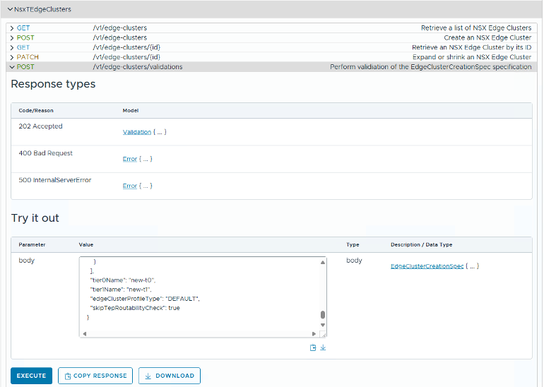
Figure 15: SDDC Manage API Edge Cluster Validation Submission
2. Retrieve results:
- Browse to /v1/edge-clusters/validations/{id}
- Enter id from previous step
- Select Execute
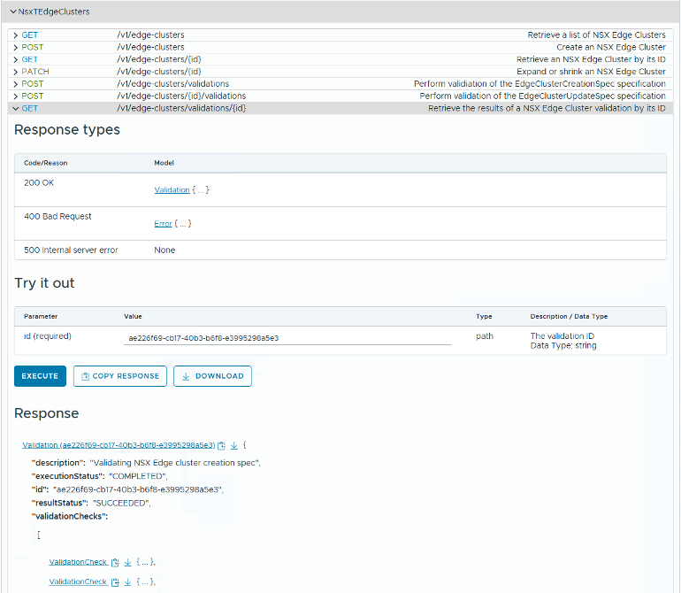
Figure 16: SDDC Manager API Edge Cluster Validation Response
3. Once validation has succeeded, execute the call to deploy the new NSX Edge Cluster via the SDDC Manager API
- Browse to /v1/edge-clusters
- Paste JSON file contents
- Choose Execute.
- Monitor the execution via SDDC Manager tasks view

Figure 17: SDDC Manage API Edge Cluster Execution Submission
Once complete, a new NSX Edge pair will be deployed in the SDDC. You now need to configure the NSX Edges to peer with the AWS RouteServer Endpoint via BGP, matching the configuration of the existing Tier-0 and Tier-1 gateways.
An NSX Tier-0 (T0) gateway provides connectivity between the NSX virtual network and the physical network, acting as a high-level router for east-west and north-south traffic.
An NSX-T Tier-1 (T1) gateway is a virtual router that provides downlink connectivity to NSX segments and northbound connectivity to a Tier-0 gateway
On the new Tier-1, make the following change:
1. Disable “Standby Relocation”
- Log in to NSX manager
- Navigate to Networking > Tier-1 Gateways and edit the new T-1 Gateway
- Select the toggle switch to disable Standby Relocation
- Save changes and select Close Editing

Figure 18: NSX Tier-1 Settings
On the Tier-0, make the following changes:
2. Change the Fail Over type
- Log in to NSX manager
- Navigate to Networking > Tier-0 Gateways and edit the new T-0 Gateway
- Use the drop-down box to select Preemptive
- Save changes

Figure 19: NSX Tier-0 Settings
3. Create a prefix list for only allowing RFC-1918 addresses to be advertised by BGP.
The prefix list prevents non RFC-1918 networks from being advertised to the route server.
- Login to NSX manager
- Navigate to Networking > Tier-0 Gateways and edit the new T-0 Gateway
- Expand the Routing section
- Select the number (in blue) next to IP Prefix Lists
- Select Add IP Prefix List
- Enter rfc-1918-allow for the name, then select Set
- Add four prefixes to match the screenshot below
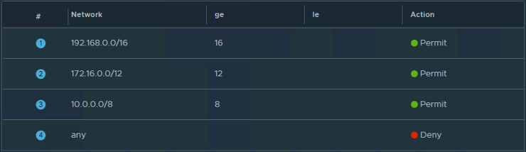
Figure 20: NSX Tier-0 IP Prefix List
- Save changes
4. Configure Static Routes on the Tier-0 Gateway
This step tells NSX how to reach the Route Server Endpoint IP addresses, as they are on a different network to the NSX Edge uplink interfaces. The first static route is the default route for all traffic exiting NSX to the VPC Underlay. The second static route points to endpoint-01 on the RouteServer, via the NSXUplink vlan gateway and the third static route points to endpoint-02 on the RouteServer, via the expansionVlan2 vlan gateway.
The Next Hop value is the gateway address for the NSX Uplink VLAN.
The first Network value is the default route, the second and third values are the IP address of each Route Server Endpoint.
- Log in to NSX manager
- Navigate to Networking > Tier-0 Gateways and edit the new T-0 Gateway
- Expand the Routing section
- Select the number (in blue) next to Static Routes
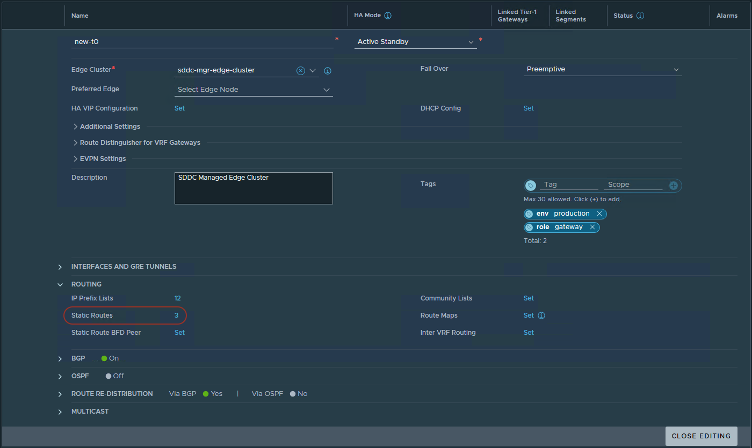
Figure 21: Static Routes Configuration
- In the window that opens, select Add Static Route
- Create three static routes, using the table below
** The values below are for illustration purposes only – please replace the values below to match your environment **
| Name | Network | Next Hop – IP Address | Admin Distance | Scope |
|---|---|---|---|---|
| 0-0-0-0-0-10-10-6-1 | 0.0.0.0/0 | 10.10.6.1 | 1 | None |
| 10-10-101-41-32-10-10-6-1 | 10.10.101.41/32 | 10.10.6.1 | 1 | None |
| 10-10-101-181-32-10-10-9-1 | 10.10.102.181/32 | 10.10.9.1 | 1 | None |
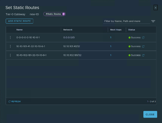
Figure 22: NSX Tier-0 Static Route Settings
5. Configure Route Re-distribution
The purpose of this step is to define what NSX will advertise via BGP. You need to configure as per the screenshot below.
- Log in to NSX manager
- Navigate to Networking > Tier-0 Gateways and edit the new T-0 Gateway
- Expand the Route Re-Distribution section
- Select the number (in blue) next to Route Re-distribution

Figure 23: NSX Tier-0 Static Route Redistribution Section
- Next, select the number (in blue) in the Route Re-Distribution column

Figure 24: NSX Tier-0 Static Route Re-distribution console
- Select Edit at the top of the new window and then configure the options to match the screenshot below
- Select Apply when complete
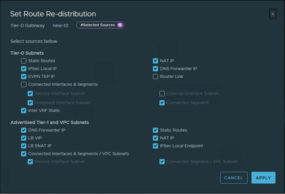
Figure 25: Route Re-distribution screen
6. Configure BGP Neighbors
The purpose of this step is to configure BGP, from the NSX Edge appliances to the VPC Route Server.
- Log in to NSX manager
- Navigate to Networking > Tier-0 Gateways and edit the new T-0 Gateway
- Expand the Routing section
- Select the number (in blue) next to BGP Neighbors

Figure 26: NSX Tier-0 BGP Neighbors Console
- In the window that opens, select Add BGP Neighbor
- Create the first BGP neighbor using the table below
** The values below are for illustration purposes only – please replace the values below to match your environment **
- The IP Address value is the IP address of the first VPC Route server endpoint
- The Remote AS Number value is the AS of the VPC Route server
- The two Source Addresses are the IP addresses of the two NSX Edge uplink interfaces that connect to Endpoint 1 on the VPC Route Server.
| IP Address | Remote AS Number | Source Addresses | Max Hop Limit | Hold Down Time | Keep Alive Time |
| 10.10.101.41 | <Route Server AS> |
10.10.9.250 10.10.9.251 |
2 | 15 seconds | 5 seconds |
- For the Route Filter setting, select the word Set (in blue) and then add a new route filter using the values below
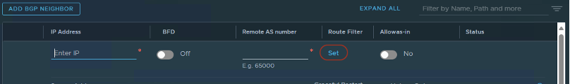
Figure 27: NSX Tier-0 BGP Console
| IP Address Family | Enabled | Out Filter |
| IPv4 | Yes | rfc-1918-only |

Figure 28: NSX Tier-0 BGP Route Filter Console
- Select Apply
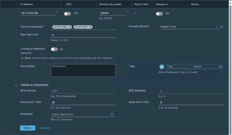
Figure 29: NSX Tier-0 BGP Route Filter Settings
- Select Apply and then Save.
- Select Add BGP Neighbor to create the second BGP Neighbor.
- Create the Second BGP neighbor using the table below
** The values below are for illustration purposes only – please replace the values below to match your environment **
- The IP Address value is the IP address of the second VPC Route server endpoint
- The Remote AS Number value is the AS of the VPC Route server
- The two Source Addresses are the IP addresses of the two NSX Edge uplink interfaces that connect to Endpoint 2 on the VPC Route Server.
| IP Address | Remote AS Number | Source Addresses | Max Hop Limit | Hold Down Time | Keep Alive Time |
| 10.10.102.181 | <Route Server AS> |
10.10.6.250 10.10.6.251 |
2 | 15 seconds | 5 seconds |
- For the Route Filter setting, select the word Set (in blue) and then add a new route filter using the values below
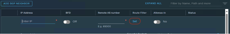
Figure 30: NSX Tier-0 BGP Console
| IP Address Family | Enabled | Out Filter |
| IPv4 | Yes | rfc-1918-only |
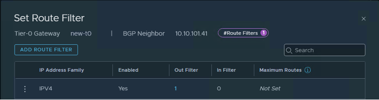
Figure 31: NSX Tier-0 BGP Route Filter Console
- Select Apply
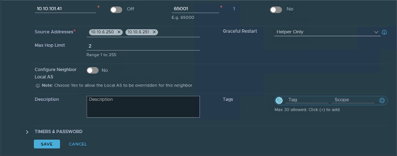
Figure 32: NSX Tier-0 BGP Route Filter Settings
- Select Apply and then save changes and Close.
After a few minutes BGP communication will be established and ready for use.
North – South traffic will now resume.
Remove old edge cluster & edge virtual machines
Once the new edge cluster has been deployed and validated, you can remove the old edge cluster and edge virtual machines, as they are no longer required.
1. Remove the original NSX Tier-1 Gateway
- Navigate to Network > Tier-1 Gateways.
- Select the ellipsis menu next to the old T1 gateway (evst1), then select Delete
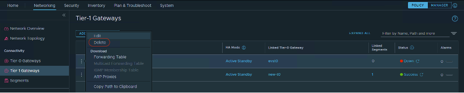
Figure 33: NSX Tier-1 Gateway Console
2. Remove the original NSX Tier-0 Gateway
- Navigate to Network > Tier-0 Gateways.
- Select the ellipsis menu next to the old T0 gateway (evst0), then select Delete
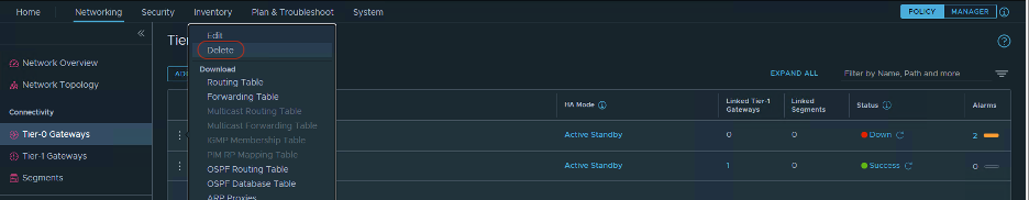
Figure 34: NSX Tier-0 Gateway Console
3. Delete the old Edge Cluster
- Navigate to System > Fabric > Nodes then select Edge Clusters.
- Select the old edge cluster and then select Delete

Figure 35: NSX Edge Cluster Console
4. Delete the Edge Nodes
- Navigate to System > Fabric > Nodes then select Edge Transport Nodes.
- Select both old edge nodes and then select Delete.
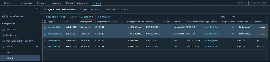
Figure 36: NSX Edge Node Console
- This action will delete the edge virtual machines from vCenter.
Conclusion
In this post you deployed a new route server endpoint and peers, a new pair of NSX Edge appliances and configured routing between the NSX-T environment and AWS VPC. You now have the ability to create Application Virtual Networks within the SDDC Manager and deploy additional VCF Components, as well as perform lifecycle management for the NSX Edges via SDDC Manager.