Containers
Implement SPIFFE/SPIRE authorization on Amazon EKS
When running distributed applications across multiple Amazon Elastic Kubernetes Service (Amazon EKS) clusters, teams face two critical security challenges: establishing secure communication in untrusted networks and authenticating workloads without relying on network-based controls.
The mTLS Challenge: Traditional approaches rely on network security to determine message sender identity and ensure message integrity. However, in complex distributed applications spanning multiple networks with services deployed by different teams, network-based protection becomes insufficient. Teams need mutual Transport Layer Security (mTLS) to cryptographically prove sender and recipient identity while ensuring messages haven’t been viewed or modified in transit.
The Authentication Challenge: While mTLS secures channels between specific workloads, teams also need flexible authentication for scenarios where direct mTLS isn’t possible—such as when Layer 7 load balancers sit between services, or when multiple workloads send messages over a single encrypted channel. JSON Web Tokens (JWTs) provide this flexibility but require proper key management and validation.
SPIFFE (Secure Production Identity Framework for Everyone) and its reference implementation SPIRE (SPIFFE Runtime Environment) help address both challenges by:
- Attesting workload identity at runtime in distributed systems
- Delivering short-lived, automatically rotated X.509 certificates (X.509-SVIDs) for mTLS directly to workloads
- Generating and validating JWT-SVIDs for flexible authentication scenarios
- Minimizing manual certificate management through the SPIFFE Workload API
This guide demonstrates deploying SPIRE in a nested configuration across multiple Amazon EKS clusters, enabling secure workload identity and authentication in distributed environments.
In this post, we show you how to implement SPIFFE/SPIRE on Amazon EKS to establish secure service-to-service communication using a nested architecture. You’ll learn how to deploy SPIRE across multiple Amazon EKS clusters, configure workload attestation, and implement fine-grained authorization policies that scale with your infrastructure.
Understanding SPIFFE/SPIRE and Service-to-Service Authorization
Before diving into the implementation, let’s establish the foundational concepts of SPIFFE and SPIRE, and understand why they’re essential for modern service-to-service authorization.
What is SPIFFE?
SPIFFE is a set of open-source standards for securely identifying software systems in dynamic, heterogeneous environments. It provides a framework for workloads to present cryptographically verifiable identities, enabling secure communication without relying on network-level controls like firewalls or IP whitelists.
What is SPIRE?
SPIRE is the reference implementation of the SPIFFE standards. It serves as a production-ready SPIFFE Runtime Environment that manages the lifecycle of SPIFFE identities, including attestation, registration, and key rotation. SPIRE can be deployed in various modes, including nested hierarchies for complex, multi-cluster environments.
Why implement SPIFFE/SPIRE? In dynamic containerized environments, traditional security approaches break down:
- IP-based security fails when containers move between nodes and clusters
- Shared secrets don’t scale across hundreds of microservices
- Manual certificate management becomes operationally complex
- Network perimeters blur in multi-cloud and hybrid deployments
SPIRE can help address these challenges by providing cryptographic identity that moves with workloads, enabling automatic credential rotation, and supporting zero-trust authentication that is designed to work across different network locations.
The Need for Service-to-Service Authorization
Traditional security models often rely on network policies or API gateways, which can be cumbersome and error-prone in microservices architectures. SPIFFE/SPIRE helps address this by:
- Providing workload identities that are cryptographically verifiable
- Enabling mutual TLS (mTLS) authentication between services
- Supporting fine-grained authorization policies based on identity
- Automating key rotation and certificate management
What is Nested SPIRE?
Nested SPIRE is a deployment architecture that allows SPIRE Servers to be “chained” together, enabling all servers to issue identities within the same trust domain. This means workloads across different clusters receive identity documents that can be verified against the same root keys, creating a unified security boundary.
How the Chaining Works:
- A SPIRE Agent is co-located with every downstream SPIRE Server
- The downstream server obtains credentials via the Workload API from its local agent
- These credentials are used to authenticate directly with the upstream SPIRE Server
- The upstream server issues an intermediate Certificate Authority (CA) to the downstream server
- All servers in the chain are configured to issue SVIDs within the same trust domain
Key Benefits:
- Unified Trust Domain: All workloads across clusters share the same cryptographic root of trust
- Multi-Cloud Ready: Different child servers can use different node attestors for various cloud environments
- Scalable Architecture: New clusters can be added by chaining additional SPIRE servers
- Centralized Root Management: Single root server manages the trust domain while child servers handle local workloads
This architecture is particularly well-suited for multi-cloud deployments where workloads need to authenticate across different infrastructure environments while maintaining a consistent security model.
Architecture Overview
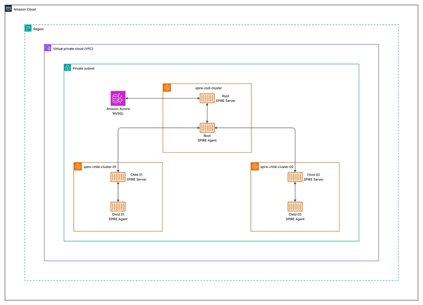
Figure 1: Nested SPIRE architecture showing root and child servers across multiple EKS clusters
Components
- Root Cluster (spire-root-cluster): Hosts the root SPIRE server
- Child Clusters (spire-child-cluster-01, spire-child-cluster-02): Host child SPIRE servers and workloads
- Amazon Aurora: Persistent datastore for the root SPIRE server
- Kubeconfig Generator: Script to create secure cluster access configurations
Node Attestation in Nested SPIRE
Before diving into the deployment process, it’s crucial to understand how SPIRE establishes trust between servers and agents across clusters through node attestation.
What is Node Attestation?
Node attestation is the process where each SPIRE agent authenticates and verifies itself when first connecting to a SPIRE server. During this process, the agent and server work together to verify the identity of the node the agent is running on using plugins called node attestors.
Node attestors interrogate a node and its environment for information that only that specific node would possess, proving the node’s identity through various methods:
- Cloud platform identity documents (such as AWS Instance Identity Documents)
- Hardware Security Module or TPM private keys
- Manual verification via join tokens
- Multi-node software system credentials (such as Kubernetes Service Account tokens)
- Deployed server certificates
Upon successful node attestation, the SPIRE server issues a unique SPIFFE ID to the agent, which serves as the “parent” identity for all workloads it manages.
Kubernetes Node Attestation (k8s_psat)
In our Nested SPIRE deployment, we use the k8s_psat plugin for node attestation. This plugin:
- Validates signed projected service account tokens provided by agents
- Uses the Kubernetes Token Review API to perform validation
- Queries the Kubernetes API server for additional node metadata (UID, namespace, service account)
- Generates SPIFFE IDs based on the validated node information
Why Cross-Cluster Access is Required
In a nested architecture, the root SPIRE server must validate tokens from child cluster nodes. This is why our deployment process includes:
- Kubeconfig generation script – Creates secure access credentials for each child cluster
- Base64-encoded kubeconfig injection – It provides the root server with child cluster API access:
--set "external-spire-server.kubeConfigs.child01.kubeConfigBase64=$(cat ../script/spire-child-cluster-01.kubeconfig)"
This cross-cluster access enables the root server to perform Kubernetes Token Review API calls against child clusters, validating that agents requesting intermediate CA certificates are legitimate nodes within the trusted infrastructure.
Prerequisites and Environment Setup
Before deploying SPIFFE/SPIRE on Amazon EKS, verify you have the following prerequisites:
Required Tools and Software
- AWS CLI: Version 2.32.0 or newer (installation guide), configured with appropriate credentials and permissions
- Terraform: Version 1.12.2 or newer (installation guide) for infrastructure provisioning
- kubectl: Version 1.34 or newer (installation guide) for Kubernetes cluster management
- Helm: Version 3.12.2 (v3 only, not v4) (installation guide) for package management
- kubectx: Version 0.9.5 (installation guide) for cluster context switching
AWS Account Requirements
You’ll need an AWS account with permissions to:
- Create EKS clusters
- Manage VPCs and subnets
- Deploy IAM roles and policies
Infrastructure Components
Our Nested SPIRE deployment consists of several key AWS infrastructure components that work together to provide secure workload identity across multiple clusters.
1. EKS Clusters
The deployment consists of three EKS clusters:
| Cluster | Purpose | Terraform Path | Region | Node Groups |
|---|---|---|---|---|
| spire-root-cluster | Hosts the root SPIRE server | infrastructure/eks/spire-root-cluster/ |
us-east-1 | Optimized for SPIRE server workloads |
| spire-child-cluster-01 | Hosts child SPIRE server and application workloads | infrastructure/eks/spire-child-cluster-01/ |
us-east-1 | Mixed instance types for diverse workloads |
| spire-child-cluster-02 | Hosts child SPIRE server and application workloads | infrastructure/eks/spire-child-cluster-02/ |
us-east-1 | Mixed instance types for diverse workloads |
2. Amazon Aurora MySQL Datastore (infrastructure/rds/spire-datastore/)
The root SPIRE server requires persistent storage for audit logs, registration entries, node attestation data, and certificate authority information.
Configuration:
- Engine: MySQL 8.0
- Instance Class: Serverless v2 (auto-scaling)
- Storage: Encrypted with AWS KMS
- Backup: Automated daily backups
- Multi-AZ: Enabled for high availability
3. Networking Architecture
Each cluster is deployed in its own or shared VPC with:
- Public Subnets: For load balancers and NAT gateways
- Private Subnets: For EKS nodes and Amazon Aurora instances
- Security Groups: Restrictive rules for inter-cluster communication
- VPC Peering: Enables secure communication between clusters
Environment Variables
Set the following environment variables:
export AWS_REGION=your-aws-region # e.g., us-east-1
export CLUSTER_NAME_ROOT=your-root-cluster-name # e.g., spire-root-cluster
export CLUSTER_NAME_CHILD1=your-child-cluster-1-name # e.g., spire-child-cluster-01
export CLUSTER_NAME_CHILD2=your-child-cluster-2-name # e.g., spire-child-cluster-02
Deploying Amazon EKS Infrastructure with Terraform
Now that we understand the architecture and components, let’s deploy the AWS infrastructure using Terraform to create our Nested SPIRE environment.
Infrastructure Overview
We’ll deploy three EKS clusters: a root cluster for the SPIRE trust anchor and two child clusters for workload deployment.
Deployment Steps
Follow these steps to deploy the infrastructure components, starting with networking, then the database, and finally the EKS clusters.
1. Obtain Networking Values
Before deploying the SPIRE infrastructure, you’ll need to gather the following networking values from your existing VPC setup:
- VPC ID
- Private subnets (list)
- Public subnets (list)
- VPC CIDR block
- Route 53 DNS zone (for external-dns to create SPIRE server domain pointing to ALB)
These values will be required for the database and EKS cluster variables.tf files in the subsequent deployment steps.
2. Deploy Aurora MySQL
Update the variables.tf file with the networking values from the previous step.
cd infrastructure/rds/spire-datastore/
terraform init
terraform plan
terraform apply
After deployment, retrieve the database endpoint and secrets ARN that will be used in subsequent configurations:
terraform output aurora_mysql_v2_cluster_endpoint
terraform output aurora_mysql_v2_cluster_master_user_secret_arn
Save these values as they will be required for the root EKS cluster and root-values.yaml configuration in the SPIRE installation steps.
3. Deploy Root EKS Cluster
Update the variables.tf file with the networking values from step 1, the database values from step 2, your Route 53 DNS zone, and RDS cluster ARN.
cd ../../eks/spire-root-cluster/
terraform init
terraform plan
terraform apply
After deployment, retrieve the IAM role ARNs that will be needed for the child cluster configurations:
terraform output cluster_iam_role_arn
terraform output node_iam_role_arn
terraform output spire_server_service_account_role_arn
Save these ARN values as they will be required for the child cluster variables.tf files.
4. Deploy Child Cluster 01
Update the variables.tf file with the networking values from step 1, the database values from step 2, and the IAM role ARNs from step 3.
cd ../spire-child-cluster-01/
terraform init
terraform plan
terraform apply
5. Deploy Child Cluster 02
Update the variables.tf file with the networking values from step 1, the database values from step 2, and the IAM role ARNs from step 3.
cd ../spire-child-cluster-02/
terraform init
terraform plan
terraform apply
6. Setup Kubeconfigs Locally
Update your kubeconfig files for all three clusters:
aws eks --region us-east-1 update-kubeconfig --name spire-root-cluster
aws eks --region us-east-1 update-kubeconfig --name spire-child-cluster-01
aws eks --region us-east-1 update-kubeconfig --name spire-child-cluster-02
7. Run the Generate Kubeconfig Script
In the script directory, execute the script to generate base64-encoded kubeconfigs:
cd script
./generate_kubeconfig.sh
What this script does:
- Creates temporary kubeconfig files for each child cluster
- Extracts cluster certificate authority data and endpoints
- Retrieves service account tokens from the
spire-systemnamespace - Generates base64-encoded kubeconfig files for secure cluster access
- Creates both encoded and decoded versions for verification
Installing SPIRE Server on EKS
With the infrastructure deployed and kubeconfigs generated, we can now install SPIRE across our clusters using Helm charts.
Helm Values Structure
The SPIRE deployment uses multiple Helm values files to organize configuration settings for different cluster roles and shared parameters.
your-values.yaml
Contains common configuration shared across all clusters:
- Image registry settings (for private registries)
- Resource limits and requests
- Security contexts
- Logging configuration
root-values.yaml
Specific configuration for the root SPIRE server:
- Database connection settings
- Trust domain configuration
- External cluster access settings
- Certificate authority configuration
spire-child-cluster-01.yaml and spire-child-cluster-02.yaml
Child-specific configurations:
- Parent server connection details
- Local cluster settings
- Node attestation configuration
Key Configuration Parameters
Root Server Configuration:
spire-server:
  dataStore:
    sql:
      databaseType: mysql
      databaseName: sharedqaspireserver
      host: "demo-serverless-mysqlv2.cluster-abc123def456.us-east-1.rds.amazonaws.com"
      port: 3306
      region: "us-east-1"
      username: spireadmin
      externalSecret:
        enabled: true
        name: spire-db-secret
        key: password

  trustDomain: "spireserver.example.com"

  nodeAttestor:
    k8sPSAT:
      serviceAccountAllowList:
        - "spire-mgmt:spire-agent"
        - "default:default"
Child Server Configuration:
spire-server:
  upstreamAuthority:
    spire:
      enabled: true
      upstreamDriver: "spire-plugin"
      serverAddress: "spire-server.spire-mgmt.svc.cluster.local"
      serverPort: 8081

  trustDomain: "spireserver.example.com"
Critical Configuration Note: Service Name Length Constraints
IMPORTANT: When deploying Nested SPIRE, the cluster identifiers used in Helm commands must be 7 characters or fewer. This is due to Internet Assigned Numbers Authority (IANA) that constraints the limit of the service names to 15 characters maximum.
- Valid service names are hereby normatively defined as follows:
- MUST be at least 1 character and no more than 15 characters long
The SPIRE Helm chart appends these identifiers to service names, causing deployment failures if too long.
- Template generates:
prom-cm-{CLUSTER_ID} - With
ABCDEFG-qa-01: becomesprom-cm-ABCDEFG-qa-01(21 characters) ❌ - With
child01: becomesprom-cm-child01(15 characters) ✅
Example of the constraint:
# ❌ This will FAIL - "ABCDEFG-qa-01" is too long (12 characters)
--set "external-spire-server.kubeConfigs.ABCDEFG-qa-01.kubeConfigBase64=..."

# ✅ This will WORK - "child01" is short enough (7 characters)
--set "external-spire-server.kubeConfigs.child01.kubeConfigBase64=..."
The cluster identifier (e.g., child01) is:
- Used only for Helm configuration – it doesn’t need to match the actual EKS cluster name
- Appended to service names by the Helm template
- Must comply with RFC 6335 naming constraints
1: Setup Root Cluster spire-root-cluster
We’ll start by configuring the root cluster, which serves as the trust anchor for our Nested SPIRE deployment.
1a. Use the Root Cluster Context
Switch to the root cluster context:
kubectx arn:aws:eks:us-east-1:111122223333:cluster/spire-root-cluster
1b. Install CRDs on the Root Cluster
Navigate back to the helm directory and install the CRDs on the root cluster:
cd ../helm
helm upgrade --install --create-namespace -n spire-mgmt spire-crds spire-crds \
--repo https://spiffe.github.io/helm-charts-hardened/
1c. Install the Root Server
Install the root server using the encoded kubeconfigs for child clusters:
helm upgrade --install -n spire-mgmt spire spire-nested --repo https://spiffe.github.io/helm-charts-hardened/ \
--set "external-spire-server.kubeConfigs.child01.kubeConfigBase64=$(cat ../script/spire-child-cluster-01.kubeconfig)" \
--set "external-spire-server.kubeConfigs.child02.kubeConfigBase64=$(cat ../script/spire-child-cluster-02.kubeconfig)" \
-f your-values.yaml -f root-values.yaml
Command Explanation:
child01andchild02are short identifiers (≤7 chars) to avoid service name length issues- These identifiers are used internally by Helm and don’t need to match cluster names
- The actual cluster access is provided by the base64-encoded kubeconfig files
- Each
kubeConfigBase64parameter contains the complete authentication information for accessing the respective child cluster
2. Setup Child Cluster spire-child-cluster-01
Now we’ll configure the first child cluster, which will connect to the root server to obtain its intermediate CA certificate.
2a. Switch to spire-child-cluster-01 Cluster
Switch to the spire-child-cluster-01 cluster context:
kubectx arn:aws:eks:us-east-1:111122223333:cluster/spire-child-cluster-01
2b. Mark spire-system namespace as Helm-managed for the spire release
kubectl label namespace spire-system app.kubernetes.io/managed-by=Helm --overwrite && kubectl annotate namespace spire-system meta.helm.sh/release-name=spire meta.helm.sh/release-namespace=spire-mgmt --overwrite
2c. Install CRDs and Server for spire-child-cluster-01
Install the CRDs and server for spire-child-cluster-01:
helm upgrade --install --create-namespace -n spire-mgmt spire-crds spire-crds \
--repo https://spiffe.github.io/helm-charts-hardened/
helm upgrade --install -n spire-mgmt spire spire-nested --repo https://spiffe.github.io/helm-charts-hardened/ \
-f your-values.yaml -f spire-child-cluster-01.yaml
3. Setup Child Cluster spire-child-cluster-02
Next, we’ll configure the second child cluster using the same process as the first child cluster.
3a. Switch to spire-child-cluster-02 Cluster
Switch to the spire-child-cluster-02 cluster context:
kubectx arn:aws:eks:us-east-1:111122223333:cluster/spire-child-cluster-02
3b. Mark spire-system namespace as Helm-managed for the spire release
kubectl label namespace spire-system app.kubernetes.io/managed-by=Helm --overwrite && kubectl annotate namespace spire-system meta.helm.sh/release-name=spire meta.helm.sh/release-namespace=spire-mgmt --overwrite
3c. Install CRDs and Server for spire-child-cluster-02
Install the CRDs and server for spire-child-cluster-02 using the specific child values file:
helm upgrade --install --create-namespace -n spire-mgmt spire-crds spire-crds \
--repo https://spiffe.github.io/helm-charts-hardened/
helm upgrade --install -n spire-mgmt spire spire-nested --repo https://spiffe.github.io/helm-charts-hardened/ \
-f your-values.yaml -f spire-child-cluster-02.yaml
Deploy Envoy Test Application
With SPIRE installed across all clusters, we’ll now deploy a test application to demonstrate secure service-to-service communication using SPIFFE identities.
1. Switch to spire-child-cluster-01
Ensure you’re connected to the child cluster:
kubectx arn:aws:eks:us-east-1:111122223333:cluster/spire-child-cluster-01
2. Update SPIFFE Trust Domain in ConfigMaps
Before deploying, update the trust domain in each configmap.yaml file under the envoy/ directory to match your root cluster’s trust domain.
For example, change:
- name: "spiffe://spirenested.example.com/ns/ecommerce/sa/edge-proxy-service-account"
The domain must match the trustDomain value in helm/root-values.yaml:
trustDomain: spirenested.example.com
3. Create Namespace and Deploy
Create the ecommerce namespace and deploy the application:
kubectl create ns ecommerce
kubectl apply -R -f envoy/
4. Get Network Load Balancer DNS
Wait for the NLB to provision, then retrieve its DNS:
kubectl get svc -n ecommerce edge-proxy -o jsonpath='{.status.loadBalancer.ingress[0].hostname}'
5. Test the Application
Access the GraphQL endpoint using the NLB DNS:
http://<NLB-DNS>:8081/v1/graphql
Example:
http://k8s-ecommerc-edgeprox-a1b2c3d4e5-f6g7h8i9j0k1l2m3.elb.us-east-1.amazonaws.com:8081/v1/graphql
Run this query to verify the deployment:
query {
  orders {
    id
    orderFor
    product {
      id
      name
    }
  },
  products {
    id
    name
  }
}
You should see data for orders and products returned successfully.
6. Introduce a SPIFFE ID Mismatch
Edit envoy/graphql/configmap.yaml line 182 and change the SPIFFE ID from plural to singular:
exact: "spiffe://spirenested.example.com/ns/ecommerce/sa/order-service-account"
Apply the change and restart the deployment:
kubectl apply -f envoy/graphql/configmap.yaml
kubectl rollout restart deployment graphql -n ecommerce
7. Observe the Error
Run the same GraphQL query. You’ll see an error for orders:
{
  "errors": [
    {
      "message": "Request failed with status code 503",
      "locations": [
        {
          "line": 2,
          "column": 3
        }
      ],
      "path": [
        "orders"
      ]
    }
  ]
}
This occurs because the SPIFFE ID no longer matches the orders service.
8. Fix the Issue
Revert the change back to the correct SPIFFE ID:
exact: "spiffe://spirenested.example.com/ns/ecommerce/sa/orders-service-account"
Apply and restart:
kubectl apply -f envoy/graphql/configmap.yaml
kubectl rollout restart deployment graphql -n ecommerce
The query should now work correctly again.
Common Issues and Solutions
1. Service Name Length Constraints
Problem: Helm template generates service names exceeding 15 characters (RFC 6335 limit) Error: must be no more than 15 characters
Root Cause: The SPIRE Helm chart appends cluster identifiers to service names. For example:
- Template generates:
prom-cm-{CLUSTER_ID} - With
ABCDEFG-qa-01: becomesprom-cm-ABCDEFG-qa-01(21 characters) ❌ - With
child01: becomesprom-cm-child01(15 characters) ✅
Solution: Use cluster identifiers of 7 characters or fewer:
# ❌ Too long - will cause deployment failure
--set "external-spire-server.kubeConfigs.routing-qa-01.kubeConfigBase64=..."

# ✅ Correct - short identifier
--set "external-spire-server.kubeConfigs.child01.kubeConfigBase64=..."
Important: The cluster identifier is only used for Helm templating and doesn’t need to match the actual EKS cluster name.
2. Image Registry Issues
Problem: Cannot pull images from public registries Solution: Configure private registry in your-values.yaml:
global:
  spire:
    image:
      registry: "your-private-registry.com"
3. Storage Class Issues
Problem: pod has unbound immediate PersistentVolumeClaims Solution: Ensure default storage class is configured:
kubectl patch storageclass gp2 -p '{"metadata": {"annotations":{"storageclass.kubernetes.io/is-default-class":"true"}}}'
4. IP Exhaustion
Problem: Not enough IP addresses in VPC CIDR Solution:
- Use larger CIDR blocks for VPCs
- Implement IP address management (IPAM)
- Consider using AWS VPC CNI with prefix delegation
5. IMDSv2 Compatibility Issue
SPIRE does not currently support IMDSv2 when strictly enforced. The Terraform configuration sets http_tokens = "optional" to allow both IMDSv1 and IMDSv2:
eks_managed_node_groups = {
  general-instances = {
    ...
    metadata_options = {
      http_endpoint = "enabled"
      http_tokens   = "optional"
    }
  }
}
Security Implications: Allowing IMDSv1 increases the risk of Server-Side Request Forgery (SSRF) attacks, as IMDSv1 does not require session tokens. To mitigate this risk:
- Implement network policies to restrict pod access to the metadata service
- Monitor IMDSv1 usage through CloudWatch metrics and VPC Flow Logs
- Apply defense-in-depth controls such as IAM role restrictions and security groups
- Review the Amazon EKS security best practices guide for additional recommendations
For an extensive review of IMDSv2 security enhancements, see Add defense in depth against open firewalls, reverse proxies, and SSRF vulnerabilities with enhancements to the EC2 Instance Metadata Service. For more details on the SPIRE limitation, see: IMDSv2 Requirement Breaks aws_mysql and aws_postgres Authentication
Verification Commands
Check SPIRE server status:
kubectl exec -n spire-mgmt spire-server-0 -- /opt/spire/bin/spire-server healthcheck
List registration entries:
kubectl exec -n spire-mgmt spire-server-0 -- /opt/spire/bin/spire-server entry show
Check agent status:
kubectl exec -n spire-mgmt daemonset/spire-agent -- /opt/spire/bin/spire-agent healthcheck
Troubleshooting Commands
Check SPIRE server logs:
kubectl logs -n spire-system deployment/spire-server
Verify agent connectivity:
kubectl exec -it spire-agent-pod -- spire-agent api fetch
Test mTLS communication:
openssl s_client -connect my-service:8443 -cert /path/to/cert.pem -key /path/to/key.pem
Best Practices and Security Considerations
1. Infrastructure Management
- Use Infrastructure as Code (Terraform) for reproducible deployments
- Implement proper tagging strategies for resource management
- Use separate AWS accounts for different environments
2. Security
- Rotate certificates regularly
- Implement comprehensive monitoring and alerting
- Use AWS IAM roles for service accounts (IRSA)
- Enable AWS CloudTrail for audit logging
3. Operations
- Implement automated backup strategies for Amazon Aurora
- Use GitOps for configuration management
- Implement proper CI/CD pipelines for updates
- Monitor resource utilization and costs
4. Scalability
- Plan for cluster growth and additional child clusters
- Implement horizontal pod autoscaling
- Use cluster autoscaling for dynamic node management
- Consider multi-region deployments for disaster recovery
5. Additional Security Considerations
- Network Policies: Implement Kubernetes network policies to restrict traffic
- RBAC: Use least-privilege service accounts
- Secrets Management: Store sensitive data in AWS Secrets Manager
- Encryption: Enable encryption at rest and in transit
- Audit Logging: Enable comprehensive audit logging
Cleanup
Before destroying the Terraform infrastructure, you must first uninstall Helm releases to remove AWS resources created by Kubernetes controllers (such as Application Load Balancers, security groups, and IAM roles).
1. Uninstall Helm Releases from Child Cluster 02
kubectx arn:aws:eks:us-east-1:111122223333:cluster/spire-child-cluster-02
helm -n spire-mgmt uninstall spire
helm -n spire-mgmt uninstall spire-crds
kubectl -n spire-system delete pvc -l app.kubernetes.io/instance=spire
kubectl delete crds clusterfederatedtrustdomains.spire.spiffe.io clusterspiffeids.spire.spiffe.io clusterstaticentries.spire.spiffe.io
2. Uninstall Helm Releases from Child Cluster 01
kubectx arn:aws:eks:us-east-1:111122223333:cluster/spire-child-cluster-01
helm -n spire-mgmt uninstall spire
helm -n spire-mgmt uninstall spire-crds
kubectl -n spire-system delete pvc -l app.kubernetes.io/instance=spire
kubectl delete crds clusterfederatedtrustdomains.spire.spiffe.io clusterspiffeids.spire.spiffe.io clusterstaticentries.spire.spiffe.io
3. Uninstall Helm Releases from Root Cluster
kubectx arn:aws:eks:us-east-1:111122223333:cluster/spire-root-cluster
helm -n spire-mgmt uninstall spire
helm -n spire-mgmt uninstall spire-crds
kubectl -n spire-mgmt delete pvc -l app.kubernetes.io/instance=spire
kubectl delete crds clusterfederatedtrustdomains.spire.spiffe.io clusterspiffeids.spire.spiffe.io clusterstaticentries.spire.spiffe.io
4. Destroy Child Cluster 02
cd infrastructure/eks/spire-child-cluster-02/
terraform destroy
5. Destroy Child Cluster 01
cd ../spire-child-cluster-01/
terraform destroy
6. Destroy Root EKS Cluster
cd ../spire-root-cluster/
terraform destroy
7. Destroy Aurora MySQL
cd ../../rds/spire-datastore/
terraform destroy
Cost Considerations
- EKS clusters: Pricing based on instance types and usage
- Amazon Aurora MySQL: Serverless v2 pricing based on compute and storage
- Data transfer: Costs for inter-cluster communication
This blog post is based on Nested SPIRE deployment patterns and AWS EKS infrastructure. Always refer to the latest SPIRE documentation and AWS best practices for the most current deployment guidance.
Conclusion
This Nested SPIRE deployment provides a robust foundation for secure workload identity management across multiple Kubernetes clusters. The architecture scales well and provides the flexibility needed for complex microservices environments while maintaining strong security postures.
By following this post, you’ve learned how to deploy SPIRE in a nested configuration on Amazon EKS, configure workload attestation and identity management, implement service-to-service authorization policies, monitor and troubleshoot your SPIFFE/SPIRE deployment, and apply best practices for production deployments.
The combination of AWS managed services (Amazon EKS, Amazon Aurora) with the Nested SPIRE architecture creates a production-ready identity infrastructure that can support enterprise-scale applications with stringent security requirements.
As cloud-native architecture continues to evolve, SPIFFE/SPIRE will play an increasingly important role in securing distributed systems. Consider exploring integrations with service meshes like Istio and monitoring tools like Prometheus to further enhance your security posture.
Ready to get started? Clone the sample repository and deploy your own nested SPIRE environment on Amazon EKS. For questions or to share your implementation experiences, join the SPIFFE community Slack or engage with the AWS community on re:Post.
For additional support and advanced configurations, refer to the SPIRE documentation and the Helm charts repository.
| Interested in hands-on experience? |