Networking & Content Delivery
Modernizing financial networks: Huatai Securities’ multicast implementation on AWS
Modernizing financial networks: Huatai Securities’ multicast implementation on AWS
Note: This post is published in collaboration with Zhonghai Hu, Senior Architect at Huatai Securities and Ricky Chu, Infrastructure Project Manager, at Huatai Financial Holdings (Hong Kong).
Huatai Securities Co., Ltd., a technology-driven securities group founded in 1991, is committed to transforming China’s securities industry through innovative financial technologies. Recently, we encountered a significant challenge while deploying our containerized trading systems on Amazon Web Services (AWS). The default configuration of Amazon Elastic Kubernetes Service (Amazon EKS) lacked native support for multicast, a critical communication method essential for achieving the data transmission our trading systems demand. To overcome this hurdle, we developed a solution using AWS Transit Gateway to enable multicast capabilities within our EKS clusters, resulting in a substantial boost to our overall trading performance.
This post explains how Huatai Securities implemented multicast for our EKS clusters using Transit Gateway, details the technical process, and this solution significantly benefits Huatai Securities by reducing bandwidth utilization and delivering a 10-fold improvement in latency for their trading operations.
Solution overview
Our solution uses the Amazon Virtual Private Cloud (Amazon VPC) CNI plugin as the primary network plugin for the EKS cluster, using Transit Gateway to provide multicast capabilities. We add the Elastic Network Interface (ENI) from the multicast domain subnet to the node, enabling multicast communication for the EKS cluster in the form of the Host-device and a custom IP Address Management (IPAM) plugin, while using the Multus plugin to support multiple network interfaces. IPAM here refers to the function responsible for allocating and managing IP addresses for pods and services within a Kubernetes cluster. This means that Pods can use VPC CNI for unicast communication, and to achieve multicast communication with the Host-device plugin and Transit Gateway together. Figure 1 shows the architectural diagram of the solution.
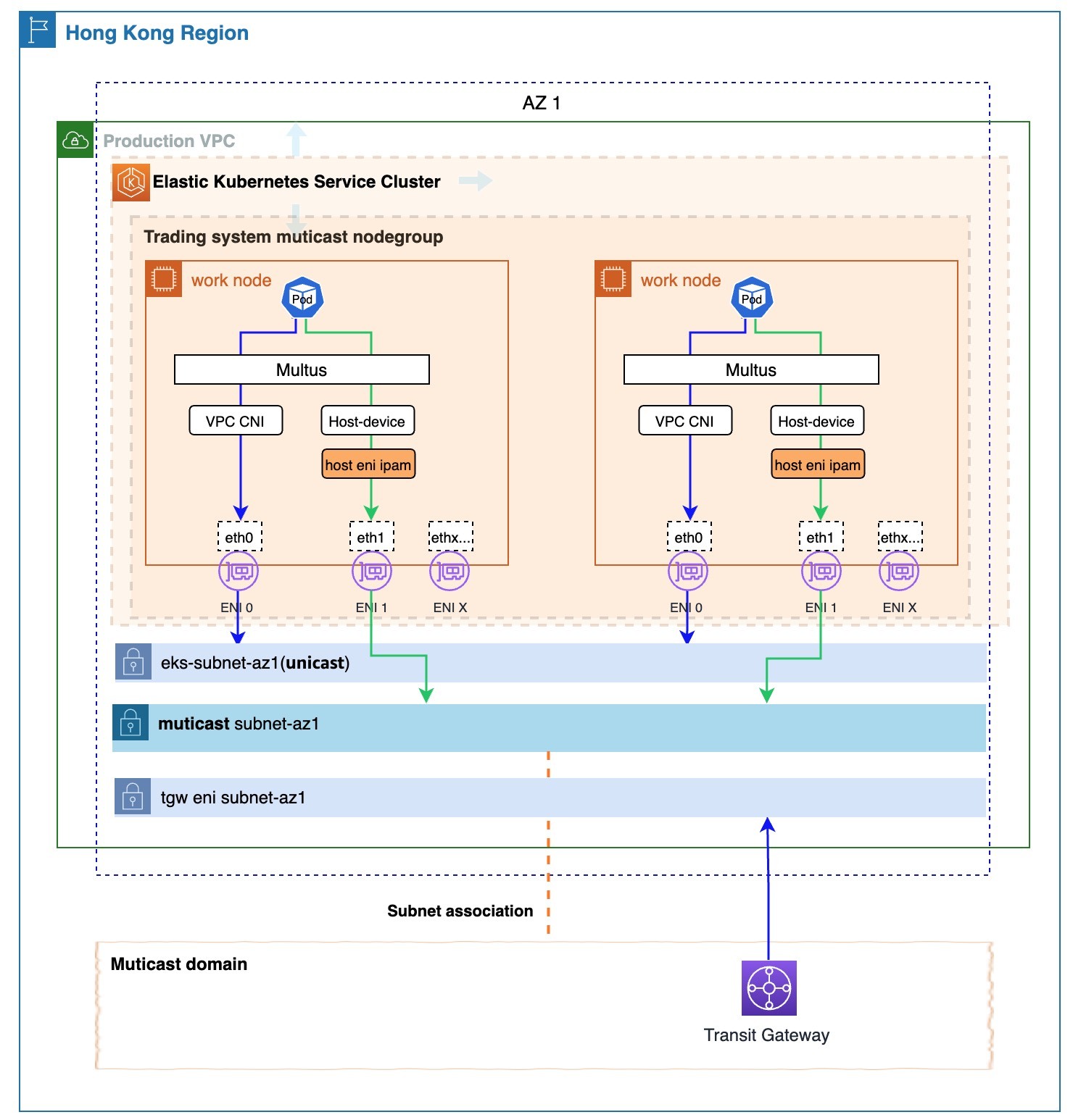
Figure 1: Multicast-enabled EKS cluster
Prerequisites
The following are necessary to deploy and verify our solution, which enables multicast in Amazon EKS:
- One VPC with three subnets (one for multicast communication, one for non-multicast communication, and one for the Transit Gateway ENI) spread across a single AWS Availability Zone (AZ)—this design was chosen to meet our low latency requirements
- A Transit Gateway with VPC attachments
- A Multicast Domain with subnet associations
- EKS cluster
- An Amazon Elastic Compute Cloud (Amazon EC2) instance that has installed eksctl and kubectl to deploy the solution and test multicast communication
Walkthrough
The following steps walk you through this solution.
Step 1: Create a Transit Gateway Domain
Create a Transit Gateway and attach the prepared VPC to it. Then, use the Transit Gateway to create an IGMP multicast domain, and associate the planned multicast subnet with the multicast domain to build the basic multicast environment. For detailed instructions on how to create an IGMP Domain using Transit Gateway, refer to the Create an IGMP multicast domain in AWS Transit Gateway documentation. Figure 2 shows an example of the created IGMP multicast domain using Transit Gateway:
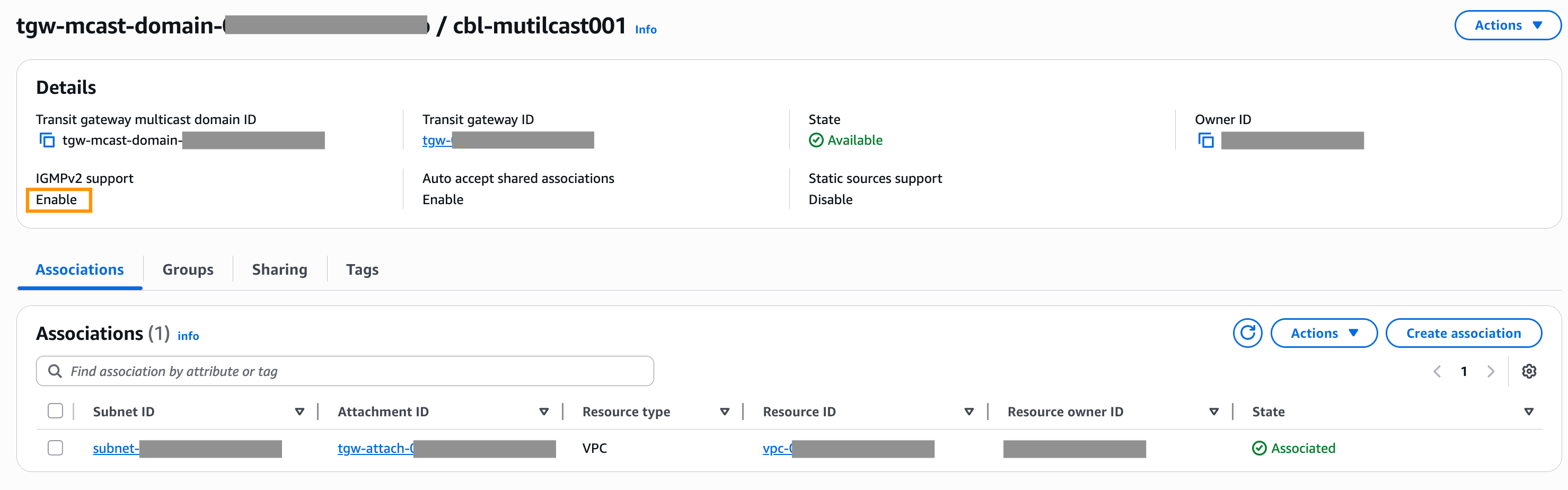
Figure 2: An example of the created IGMP multicast domain using Transit Gateway
Step 2: Create EKS cluster
Use the planned VPC and EKS subnets to create the cluster. You can use the eksctl CLI-tool to create it with the following command. Due to security requirements, we are creating a private EKS cluster.
eksctl create cluster -f {cluster_define_yaml_filepath}
You can refer to the example in Figure 3 for the YAML file definition:
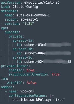
Figure 3: An example for the YAML file definition of creating an EKS cluster
Step 3: Check and configure the EKS cluster VPC CNI plugin’s ENI warm pool parameter
The default value for the WARM_ENI_TARGET parameter of the VPC CNI is set to 1 by default, which means that one extra ENI is added to one of the nodes in the NodeGroup. However, this leads to inconsistent ENI counts across nodes, which can complicate multicast configuration. To avoid this, we explicitly set WARM_ENI_TARGET to 0, disabling the warm pool. This makes sure that each node in the newly created NodeGroup has only one ENI.
kubectl set env daemonset aws-node -n kube-system WARM_ENI_TARGET=0
Step 4: Create a NodeGroup for multicast communication
We used eksctl to create a NodeGroup. Make sure to specify the SSH key for node access to facilitate later operations.
eksctl create cluster -f {cluster_define_yaml_filepath}
You can refer to the example in Figure 4 for the YAML file definition:
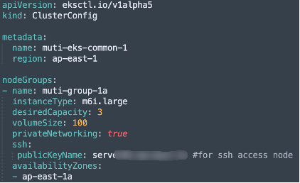
Figure 4: An example for the YAML file definition of creating a NodeGroup
Step 5: Create Multicast ENIs, configure security groups, set key tags, and attach ENIs to nodes
When creating multicast ENIs (the number of ENIs should match the number of nodes in the NodeGroup created for multicast communication), there are two key points:
- Note 1: Assign a security group to each multicast ENI that allows multicast communication.
- Note 2: By default, ENIs attached to nodes are managed by the VPC CNI plugin. To prevent the multicast ENIs from being managed by the plugin, set the following tags on each ENI:
| key | value |
| node.k8s.amazonaws.com/no_manage | true |
After we attached the created ENI to the node, we could SSH into the node to verify that a network interface named eth1 is visible, as shown in Figure 5.
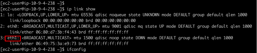
Figure 5: A network interface named eth1 is visible in the node
Step 6: Install the Multus plugin
Refer to the Apply AWS Auth Configmap GitHub link to modify the Auth ConfigMap, and the Install Multus GitHub link to install the Multus plugin.
Use the kubectl command to confirm that installation was successful. You should see a pod named kube-multus-xxxx running normally in the kube-system namespace.
Step 7: Configure IGMP kernel parameters on Nodes and set up custom IPAM plugin
We logged in to each node and set the following kernel parameters:
sudo sysctl -w net.ipv4.conf.all.force_igmp_version=2
sudo sysctl -w net.ipv4.conf.default.force_igmp_version=2
If you want these settings to persist, then you can add the two parameters to the end of the /etc/sysctl.conf file and run the following command:
sudo sysctl -p
Copy the custom-developed IPAM plugin to the /opt/cni/bin directory on the node, and make it executable:
sudo cp {your ipam file path} /opt/cni/bin/{ipam_filename}
sudo chmod +x /opt/cni/bin/{ipam_filename}
The main function of the IPAM plugin here is to assign the IP of the node’s multicast ENI to the pod’s multicast network interface. This allows the program to access the multicast network interface through that IP.
The sample code of the custom IPAM plugin implementation is as follows:
#!/bin/bash
# need to grant execute permissions with chmod +x.
# When configuring, it needs to be placed in the CNI plugin directory (typically /opt/cni/bin/).
# Logging function
log() {
echo "{\"timestamp\":\"$(date -u '+%Y-%m-%dT%H:%M:%SZ')\",\"message\":\"$1\"}" >&2
}
# Function to get the EC2 subnet CIDR.
get_ec2_interface_info() {
local mac=$1
# Get IMDSv2 token
local token=$(curl -s -X PUT "http://169.254.169.254/latest/api/token" -H "X-aws-ec2-metadata-token-ttl-seconds: 21600")
if [ -z "$token" ]; then
log "Failed to get IMDSv2 token"
exit 1
fi
# Get the IP address corresponding to this MAC address (local-ipv4s may return multiple IPs, take the first one)
local ip=$(curl -s -H "X-aws-ec2-metadata-token: $token" http://169.254.169.254/latest/meta-data/network/interfaces/macs/${mac}/local-ipv4s | head -n 1)
if [ -z "$ip" ]; then
log "Failed to get IP for MAC $mac"
exit 1
fi
# Get subnet CIDR
local cidr=$(curl -s -H "X-aws-ec2-metadata-token: $token" http://169.254.169.254/latest/meta-data/network/interfaces/macs/${mac}/subnet-ipv4-cidr-block)
if [ -z "$cidr" ]; then
log "Failed to get subnet CIDR from metadata service"
exit 1
fi
local mask=$(echo "$cidr" | cut -d'/' -f2)
echo "$ip/$mask"
}
# get the MAC address of the container
get_container_mac() {
local ifname=$1
local netns_path=$2
local netns=$(basename "$netns_path")
# Get the MAC address in the container network namespace
local mac=$(ip netns exec "$netns" ip link show "$ifname" | grep ether | awk '{print $2}')
if [ -z "$mac" ]; then
log "Failed to get MAC address for interface $ifname"
exit 1
fi
echo $mac
}
# Process CNI commands
case "$CNI_COMMAND" in
ADD)
# Verify required environment variables
if [ -z "$CNI_IFNAME" ] || [ -z "$CNI_NETNS" ]; then
log "Missing required CNI variables"
exit 1
fi
log "Processing ADD for interface $CNI_IFNAME in netns $CNI_NETNS"
# get container mac
mac_addr=$(get_container_mac "$CNI_IFNAME" "$CNI_NETNS")
log "Got container MAC address: $mac_addr"
# Get the EC2 IP
iface_ip=$(get_ec2_interface_info $mac_addr)
log "Got Interface IP: $iface_ip"
# Construct the CNI return result
cat << EOF
{
"cniVersion": "0.3.1",
"interfaces": [
{
"name": "$CNI_IFNAME"
}
],
"ips": [
{
"version": "4",
"address": "$iface_ip"
}
]
}
EOF
;;
DEL)
# For DELETE operations, simply return success.
log "Processing DEL for interface $CNI_IFNAME"
cat << EOF
{
"cniVersion": "0.3.1"
}
EOF
;;
*)
log "Unsupported CNI command: $CNI_COMMAND"
exit 1
;;
esac
exit 0
Step 8: Deploy NetworkAttachmentDefinition for Multicast Communication
The YAML file defining the NetworkAttachmentDefinition is shown as follows:
apiVersion: k8s.cni.cncf.io/v1
kind: NetworkAttachmentDefinition
metadata:
name: hostdevice-multicast-network
namespace: kube-system
spec:
config: '
{
"cniVersion": "0.3.1",
"type": "host-device",
"device": "eth1",
"ipam": {
"type": "{ipam_filename}"
}
}'
The ipam_filename here must be the same as the ipam_filename located in /opt/cni/bin/ on the node.
We use the following command to deploy the NetworkAttachmentDefinition:
kubectl apply -f {NetworkAttachmentDefinition_filepath}
Step 9: Create pods for multicast communication
In the pod definition file, set the k8s.v1.cni.cncf.io/networks attribute under metadata.annotations to the name of the above NetworkAttachmentDefinition. This enables the pod to support multicast communication.
A reference to the key part of the YAML file is shown as follows:
apiVersion: v1
kind: Pod
metadata:
name: multitool-with-iperf-muti01
annotations:
k8s.v1.cni.cncf.io/networks: {hostdevice-multicast-network}
labels:
app: multitool-with-iperf-muti01
spec:
…
At this point, the EKS cluster is capable of multicast communication between pods as well as between pods and virtual machines (VMs).
Demonstrating multicast operation
Now we can create pods and test multicast traffic among these pods:
Step 1: Create three pods for testing
Create three pods that support multicast for testing. The core part of the test pod definition file is as follows:
spec:
…
containers:
- name: multitool
image: praqma/network-multitool
command: ["/bin/bash"]
args:
- "-c"
- "apk update && apk add iperf && /usr/sbin/nginx -g 'daemon off;' & while true; do sleep 3600; done"
…
Step 2: Test multicast traffic between three pods
We use pod3 to send UDP packets to the multicast address 224.0.0.13 through the multicast network interface, using the following command:
iperf -B 10.9.1.40 -c 224.0.0.13 -u --ttl 5 -t 3600 -b10M
On pod1 and pod2, we use the following command to instruct the multicast network interface to receive multicast UDP packets from the multicast address 224.0.0.13:
iperf -s -u -B 224.0.0.13%net1 -i 1
The results are shown in Figure 6 where pod1 and pod2 successfully receive the multicast packets.
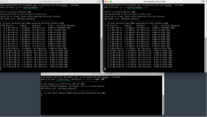
Figure 6: pod1 and pod2 successfully receive the multicast packets
At this point, by checking the multicast domain console of the Transit Gateway, we can see the activity information of the multicast group (224.0.0.13), as shown in Figure 7.
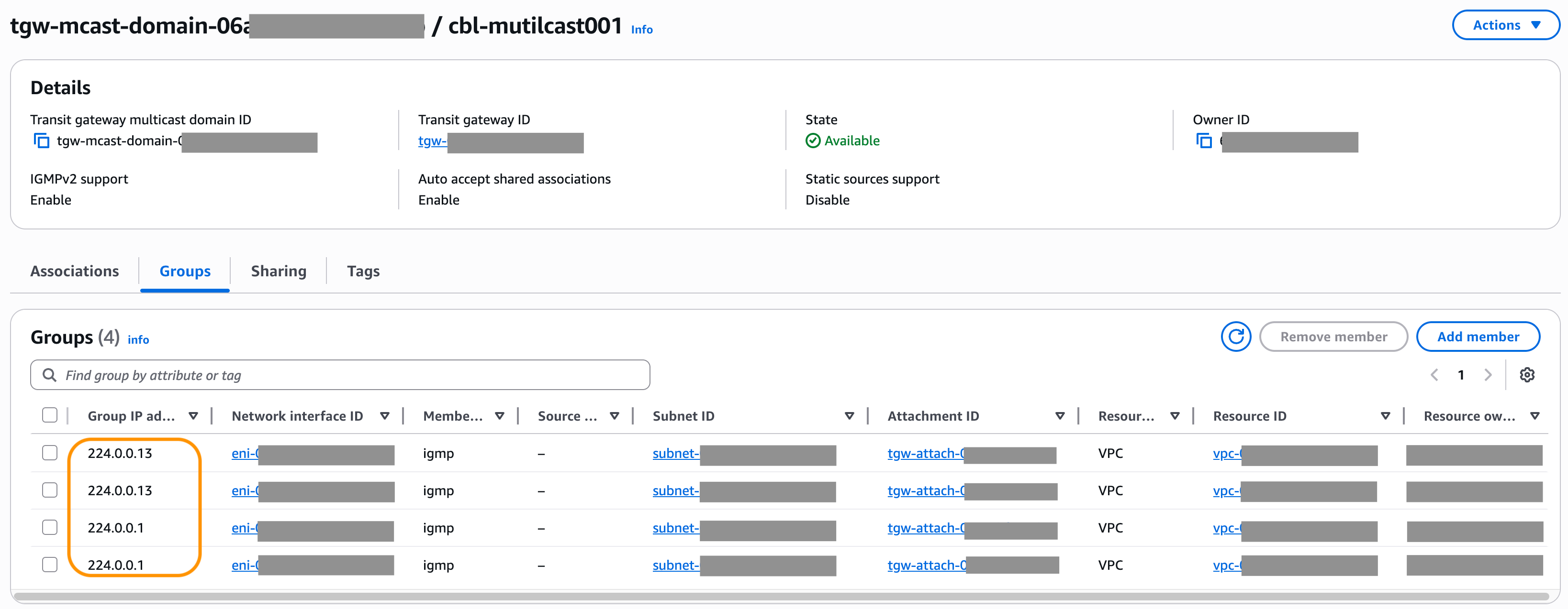
Figure 7: Multicast groups information shown in in Transit Gateway
Next, we launch an EC2 instance within the multicast subnet and have it send multicast traffic to the multicast group 224.0.0.13. Then, we can observe that pod1, pod2, and pod3 all successfully receive the multicast traffic, as shown in Figure 8.
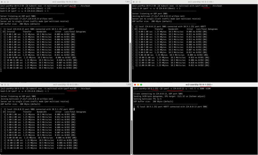
Figure 8: pod1, pod2, and pod3 all successfully receive the multicast traffic sent from the new EC2 instance
Results
During the testing phase of this solution, the average network latency using hping3 (TCP mode) within the same Availability Zone was 6 ms (as the trading system’s unicast traffic is carried over TCP). In contrast, the average network latency using mping for multicast traffic within the same Availability Zone was 0.4 ms—representing a more than 15-fold increase in latency for the TCP-based unicast traffic. Although the actual production trading system processing is more complex and the paths are longer, the components of the trading system that use multicast communication still achieve a more than 10-fold improvement in latency.
Multicast limits
The Transit Gateway multicast feature is best suited for general multicast applications within the financial industry and may not be appropriate for high-frequency trading or high-performance workloads. Consult with your AWS representative to determine suitability for your specific performance requirements.
We recommend that you review the Multicast section of the Transit Gateway Quotas document and plan your deployment accordingly.
Conclusion
In this post, we introduce an Amazon EKS multicast communication solution, built upon AWS Transit Gateway, that provides multicast capabilities to EKS clusters by adding extra ENIs, without impacting the Amazon VPC CNI plugin. This solution removes the obstacles for Huatai Securities to deploy their containerized core trading systems on AWS. Furthermore, it offers valuable insights for other users who need multicast capabilities in scenarios where VPC CNI is the primary network plugin. This solution significantly benefits Huatai Securities by reducing bandwidth utilization and delivering a 10-fold improvement in latency for their trading operations.Try our solution to improve the network processing efficiency of your system, or read the Transit Gateway multicast feature to build your own solution.
About the authors

Kevin Liu
Kevin Liu, Senior Networking Specialist at Amazon Web Services China. Responsible for consulting and designing cloud computing network solution architectures based on AWS. Currently dedicated to research in the areas of networking and Network-as-a-Service.

Baoliang Cui
Baoliang Cui is an FSI solutions architect at AWS with 15 years of software development experience and 5 years as an architect. He has been involved in two cloud computing startups and currently serves leading securities firms at FSI. He is passionate about traditional Chinese wellness practices and tea ceremonies.

Zhonghai Hu
Zhonghai Hu, an Architect, Architecture Committee, Huatai Securities

Ricky Chu
Ricky Chu, Infrastructure Project Manager, IT Department, Huatai Financial Holdings (Hong Kong).