Networking & Content Delivery
Securing Egress Architectures with Network Firewall Proxy
Note: Dec 4, 2025 – expanded with additional section on application networking integrations.
Customers who control access out of their AWS environments using self-managed proxies often find it challenging to deploy, scale, and patch their EC2 or container-based proxy fleets. With the recent launch of AWS Network Firewall proxy preview, AWS is taking over the heavy lifting of proxy management and deployment, allowing customers to focus on just the security policies that control outbound access from their VPCs.
In this blog post, we cover the workings of the proxy along with the steps to set it up. The post will also discuss the network connectivity options for proxy and various architectural patterns. The proxy filters traffic before it’s allowed to reach destinations on the Internet, in AWS, or even on-premises.
Proxy Connectivity Components
Network Firewall proxy is directly integrated with the NAT Gateway service that runs inside the VPC and takes care of IP address translation for outbound traffic. Your applications can access the proxy from the local or remote VPCs using a proxy-specific VPC interface endpoint powered by AWS Private Link. Figure 1 depicts the components involved in traffic forwarding and their function.

Figure 1. Proxy components
How Does Network Firewall Proxy Inspect My Traffic?
Network Firewall proxy offers explicit inspection of your network traffic. That is, you set up your applications to send HTTP CONNECT requests to the proxy, and the proxy establishes a new connection with the desired destination on the application’s behalf while performing inspection at multiple phases. For plaintext HTTP request the proxy also supports handling of the absolute-form of the HTTP request.
In total, the proxy inspects your traffic at three different phases in the following order:
- PreDNS – applied before the proxy tries to resolve DNS for the desired destination domain
- PreRequest – applied before the proxy sends a HTTP request to the destination server
- PostResponse – applied after the proxy receives a HTTP response from the destination server
Evaluation of each phase is a stage in a packet flow that allows the administrator of the proxy to apply access rules. If an earlier phase blocks traffic subsequent phases do not get triggered. Figure 2 depicts TCP connection establishment, HTTP request and response flow, and location of each inspection phase.
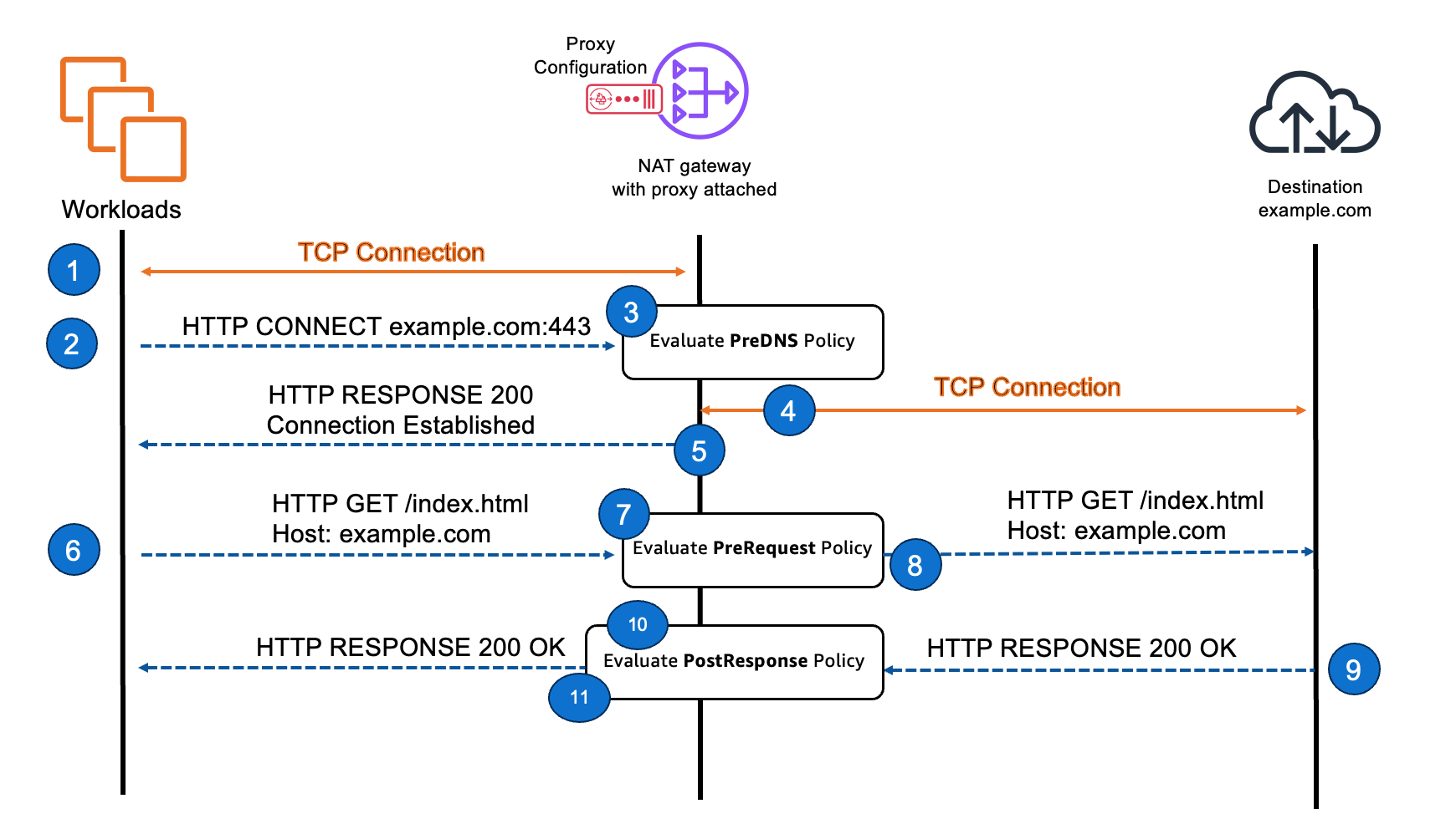
Figure 2. TCP connection and request flow through the proxy
- Workload establishes a TCP connection with the proxy
- Workload sends an HTTP CONNECT message to indicate it wants to connect through the proxy to a specific destination
- Proxy evaluates PreDNS policy first, and if the domain is allowed, it performs DNS resolution using the VPC’s designated DNS resolver to get the destination’s IP address
- Proxy establishes a TCP connection with the returned IP address of the destination
- Proxy sends HTTP response to workload indicating the connection to the destination is established
- Workload sends an HTTP GET request to the proxy for the same domain previously included in the CONNECT request.
- Proxy evaluates the PreRequest policy to validate if the request should be allowed
- If the request is allowed, proxy sends its own GET request to the destination
- Destination responds with appropriate details
- Proxy evaluates response using PostResponse policy
- If the response is allowed, proxy sends the response payload to the workload
Network Firewall’s proxy can be configured to either intercept TLS or allow TLS to pass through untouched. When TLS interception is enabled, the proxy terminates the TLS session from the workload and initiates a new TLS session toward the destination. To do this, the proxy generates a certificate on behalf of the real destination and presents it to the workload. For this to work, the workload must trust the proxy’s certificate authority; the process for establishing that trust is covered in a later section. With interception enabled, the proxy can inspect HTTP-layer content and apply fine-grained policies.
When TLS interception is disabled, the proxy still creates two independent TCP connections – one between the workload and the proxy, and one between the proxy and the destination. However, the TLS handshake occurs directly between the workload and the destination, creating an end-to-end encrypted tunnel. In this mode, the proxy cannot decrypt or inspect the encrypted payload and can only enforce policies based on unencrypted metadata such as DNS, IP address, or SNI.
Figure 3 illustrates the difference between flows with TLS interception enabled versus disabled.
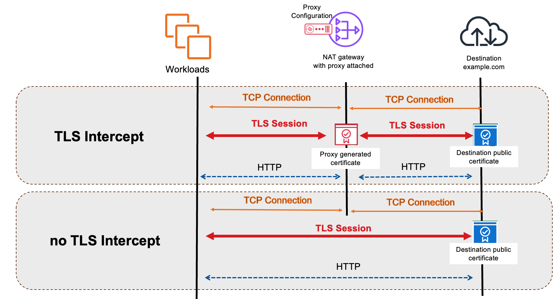
Figure 3. Proxy flow with and without TLS interception
Getting Started
At a high level, you can set up Network Firewall proxy following these three steps:
- Create and populate a proxy configuration: A proxy configuration allows you to configure your filtering rules in their desired priority of implementation.
- Create the proxy and [optional] establish trust with the clients: Use the proxy configuration created in Step 1 to create a proxy. You will also need an existing NAT Gateway to integrate with the proxy. Optionally, to perform TLS inspection, you must establish trust between the proxy and the clients
- Configure your clients to use the proxy: You need to explicitly configure your clients to use the Network Firewall proxy
Step 1: Creating a Network Firewall proxy configuration
A proxy Configuration is a top-level container where you can configure all your filtering rules that you want to apply to the traffic. You can arrange these rules in order of desired priority in sharable containers called rule groups.
To create a proxy configuration, first navigate to Amazon VPC console and under the navigation pane choose Proxy rule groups. Then create a rule group, give it a name and populate it with filtering rules. The rule language mimics the proxy’s filtering behavior across the different phases.
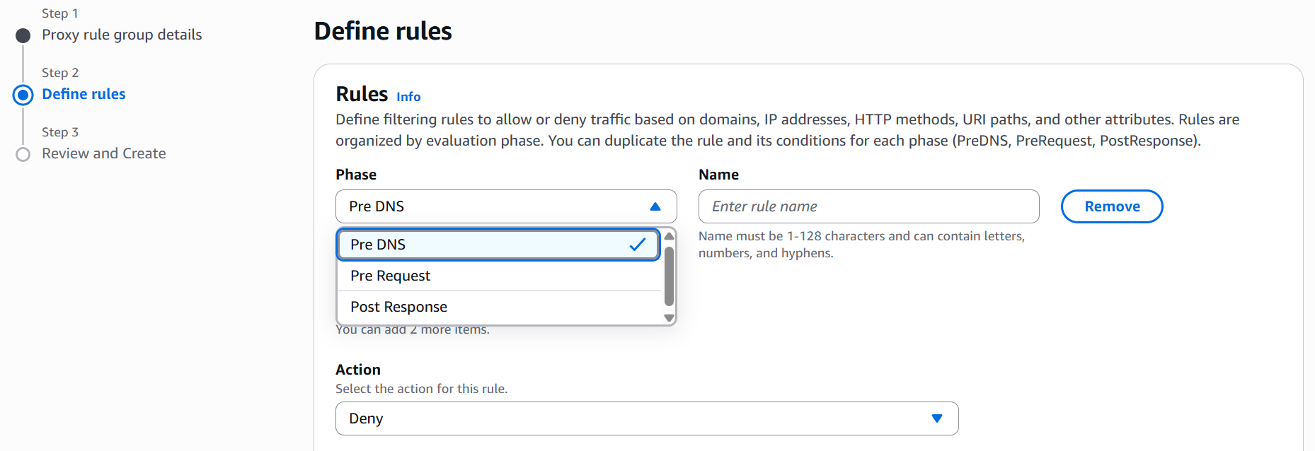
Figure 4. Rule Entry for Different Traffic Phases In a Rule Group
You can define the match conditions by choosing from the different condition keys and operators and then entering the appropriate match value.
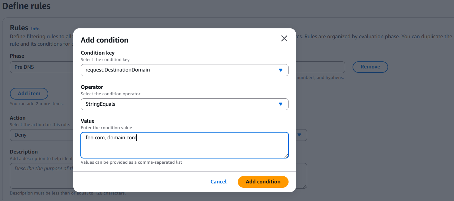
Figure 5. Example Match Criteria for a Rule
You can choose to create multiple match conditions for a single rule. Refer to the documentation for details on condition key options and examples of filtering rules. The rule is only implemented if all the conditions are matched. You can use these conditions to create fine-grained and source-specific rules. Once you have defined the match conditions, you can choose the action – allow, deny or alert – and create the rule.
You can create up to a thousand rules in a rule group and arrange them in order of desired priority. The Network Firewall proxy evaluates rules sequentially in order of priority. Rules are processed in order based on their insert position, with lower numbers receiving higher priority. Within each phase, evaluation continues until the first matching rule is found. When a rule matches, the outcome follows strict patterns:
- A deny action immediately blocks traffic and ends all further rule processing.
- An allow action ends processing in the current phase but still requires evaluation in later phases.
- An alert action logs the event and allows evaluation to continue.

Figure 6. Setting Priorities for Different Rules in a Rule Group
You can create multiple rule groups and store them. Different organizational units in your company can create rule groups specific to their own unit and share them with you for implementation on the proxy.
You can consolidate the different rule groups in a single Network Firewall proxy configuration. When you create a proxy configuration, you must select the default action for each phase. The default action is applied when none of the rules in any of the rule groups match the traffic.
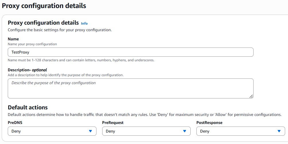
Figure 7. Creating Proxy Configuration With Default Action for Different Phases
Once you have defined the default actions, you can then attach the different rule groups with their relative priority.

Figure 8. Attaching Rule Groups to a Proxy Configuration
You can then review all the rule groups in one place and create the Network Firewall proxy configuration.
Step 2: Creating Network Firewall proxy using the proxy configuration
In addition to proxy configuration you need a NAT Gateway in your account to complete the setup. You can associate the proxy configuration and selected NAT Gateway in the proxy console. During the association process a proxy endpoint is created automatically in the subnet of the NAT gateway.
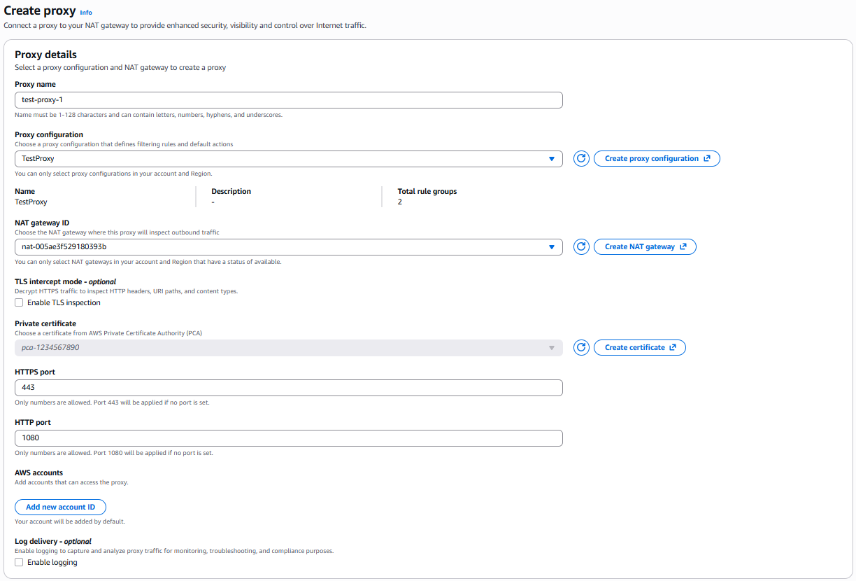
Figure 9. Proxy Creation using Proxy Configuration and NAT Gateway
In the creation workflow, you are also required to select whether you want to enable TLS mode in your proxy. To enable TLS interception, you must set up trust between the clients and the proxy. Once your clients trust the forward certificates generated by the proxy, the proxy can decrypt your traffic.
To set up trust, you must import the root certificate of your enterprise certificate authority (CA) into the trust store of your operating system or the application. Your clients will then trust all certificates that are signed by subordinate CAs chained to your enterprise CA.
To use proxy, you can use your existing enterprise CA to sign a private subordinate CA certificate that AWS Private Certificate Authority manages. For more details on importing externally signed CA certificates refer to AWS documentation.
Alternatively, you can create either root CAs or subordinate CAs using AWS PCA. Refer to documentation for detailed setup instructions. Your proxy uses this subordinate CA to sign all the certificates it automatically generates on behalf of the destination server that are subsequently sent to the client to establish trust.
Step 3: Configuring applications to use the Network Firewall proxy
Network Firewall proxy is an explicit proxy, which means you don’t need to set up routing rules to forward traffic to a proxy. Instead, you must explicitly configure your workload to use the proxy endpoint for any HTTP/HTTPS communication. Configuring your workload to use an explicit proxy can differ depending on the operating system or application used. For example, Linux uses environment variables to send traffic to a proxy:
export https_proxy="https://proxy_host:proxy_port"
export http_proxy="https://proxy_host:proxy_port"
HTTP CONNECT requests to Network Firewall proxy can be made over either HTTP or HTTPS based on your endpoint configuration, regardless of whether TLS interception is enabled. When using HTTPS, the initial connection leverages Amazon’s public certificate for the proxy endpoint, which is signed by ACM and trusted by standard trust stores.
You can find your proxy hostname and the HTTP and HTTPS ports in the proxy console under Private DNS name and Listener properties depicted in Figure 10.

Figure 10. Proxy hostname and listener ports
When a proxy is created and attached to a NAT Gateway, Network Firewall automatically creates a PrivateLink endpoint in the same subnet as the NAT Gateway.
For workloads in the same VPC as the proxy, no additional endpoints are required.
For workloads in other VPCs, you only need to create a PrivateLink endpoint in each VPC that cannot directly route to the proxy endpoint.
Private subnets also do not need a default route to the Internet to send traffic through the proxy—they only need to reach the proxy endpoint, which uses an IP address from the VPC CIDR range. (Preview supports IPv4 only.) Figure 11 shows an example routing configuration for a single VPC.

Figure 11. Network Firewall proxy access
Now that we know how to set up Network Firewall proxy and use it with your applications, the remaining post will discuss the different architectural and deployment patterns that customers can use.
Proxy Access Patterns
Network Firewall proxy can be used to protect traffic from the local VPC, remote VPC, or even on-premises sources. As long as your workload has connectivity to the proxy endpoint, it can use the proxy service. Note that traffic can only reach the proxy through an endpoint. If you simply route traffic to the NAT Gateway, it will not apply proxy policies on it.
Because the proxy is attached to a NAT Gateway, it can reach the same destinations as the NAT Gateway. This includes destinations on the Internet, on-premises, or even in other VPCs. Figure 12 shows examples of traffic sources and destinations.
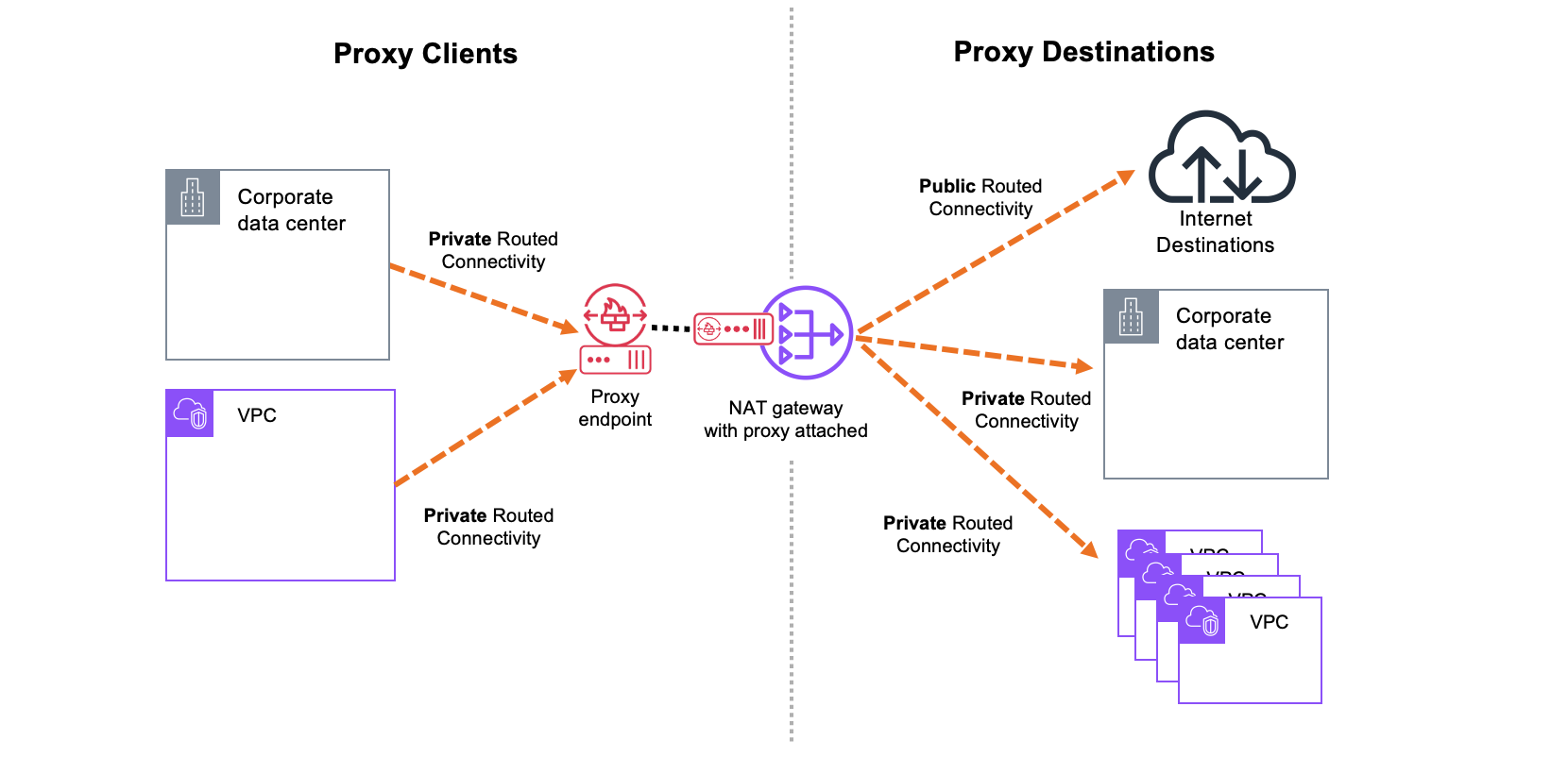
Figure 12. Proxy Sources & Destinations
Multi-VPC Connectivity Options
Just like networking patterns with NAT Gateway, you can either distribute or centralize your proxy connectivity. In the distributed model, you deploy a NAT Gateway with proxy in every VPC.

Figure 13. Distributed proxy model
Customers would typically prefer a centralized model to optimize costs and better utilize the NAT Gateways and proxy. In a centralized model, you can share a single NAT Gateway and proxy across multiple VPCs by exposing them through a proxy Endpoint. Alternatively, you can use a networking construct such as AWS Transit Gateway or AWS Cloud WAN to route traffic from multiple VPCs to a central proxy endpoint.
Figure 14 shows centralized egress connectivity through the proxy endpoints. Because the endpoints are powered by PrivateLink and hosted inside each VPC, no additional routing configuration is required. Traffic that needs to reach the proxy connect to a local endpoint IP address in each VPC.
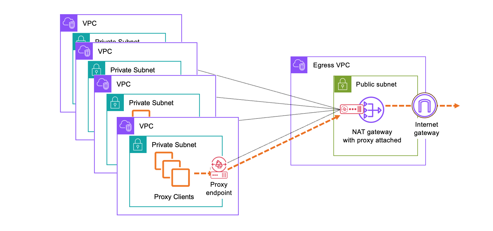
Figure 14. Centralized proxy egress through proxy endpoint
In contrast to the endpoint model, centralizing egress traffic through AWS Cloud WAN or AWS Transit Gateway requires updates to the route tables in the participating VPCs and connectivity components to ensure all clients can reach the proxy endpoint in the egress VPC. The choice between these models typically comes down to cost considerations and whether a Transit Gateway or Cloud WAN deployment already exists. If no such infrastructure is in place, customers should use the endpoint model. When a Transit Gateway or Cloud WAN is already part of the architecture, they can be leveraged to centralize egress and optimize for endpoint hourly costs.
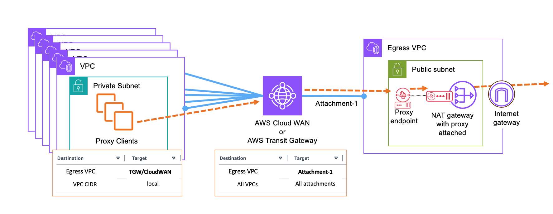
Figure 15. Centralized egress with AWS Cloud WAN or AWS Transit Gateway
Proxy today only supports handling HTTP/HTTPS traffic. If you want to combine proxying of those flows with another security solution handling non-HTTP traffic, you could combine the proxy and routed models in the same architecture. Proxy is accessed via endpoint and used for HTTP traffic, and Transit Gateway or Cloud WAN are used for routing non-HTTP traffic. Figure 16 shows a combined model where HTTPs traffic is using proxy and non-HTTPs traffic is using traditional firewalling with AWS Network Firewall.
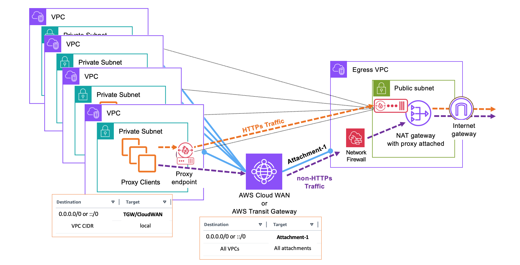
Figure 16. Combination of proxy and non-proxy traffic
This model uses the NAT Gateway in two distinct modes. First, it receives routed traffic that has already been inspected by AWS Network Firewall (or another gateway-mode security solution using Gateway Load Balancer). This routed traffic is not proxied. Separately, the NAT Gateway also receives proxied traffic forwarded by the proxy, which in turn receives that traffic through endpoints from multiple VPCs. Only the traffic that arrives through the proxy endpoint path is subject to proxy functionality.
Proxy Integrations With Application Networking Services
You can deploy Network Firewall proxy behind AWS application networking services, including Amazon VPC Lattice and VPC endpoints exposed through a Network Load Balancer (NLB). Integration with Resource Endpoints is also supported and follows the same pattern as VPC Lattice.
When integrating with these services, note that the source traffic is NATed, meaning the proxy does not receive the original client IP address. As a result, policies that rely on the real client IP cannot be evaluated.
Integration with Amazon VPC Lattice
To use Network Firewall proxy with VPC Lattice, add the proxy as a new resource configuration within an existing service network. The resource configuration requires a target domain that Lattice will forward traffic to. You must provide the VPC endpoint’s autogenerated domain name (for example,
vpce-123.abc.proxy.nfw.us-east-2.vpce.amazonaws.com) rather than the proxy’s own service domain (such as abc.proxy.nfw.us-east-2.amazonaws.com).
Although these domains appear similar, only the VPCE domain is publicly resolvable, which is required for proper routing. You can locate this endpoint domain by navigating to the Endpoints list in the VPC console and selecting the endpoint associated with your proxy.
The proxy’s service domain, on the other hand, can be used as a custom domain for the Lattice resource. For more information on custom domains in VPC Lattice, see Custom domain names for VPC Lattice resources. Figure 17 illustrates the VPC Lattice integration model.
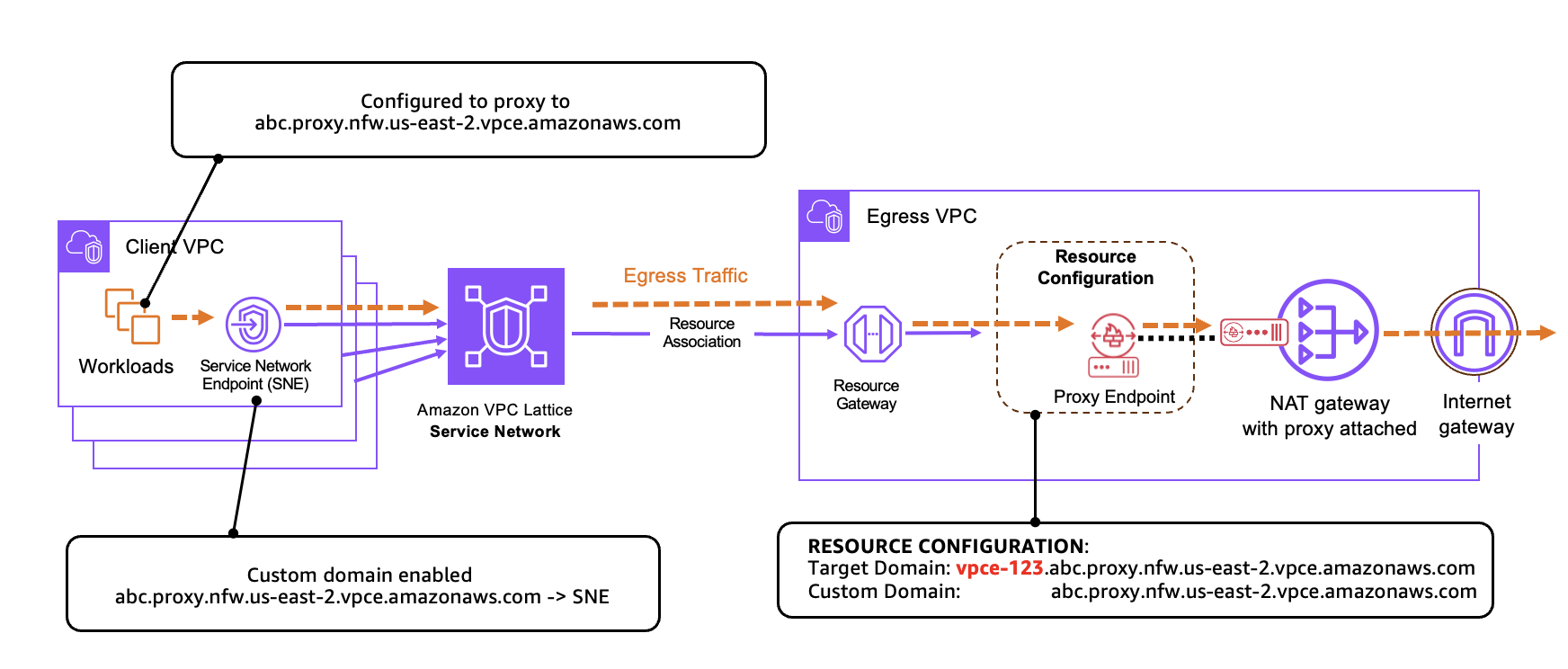
Figure 17. Proxy endpoint behind Amazon VPC Lattice
To learn more about configuring Lattice resources, refer to Streamline and secure access to shared services and resources with Amazon VPC Lattice.
Cross-Region support using VPC endpoints
To extend proxy access across Regions, you can deploy the proxy behind an NLB and expose it through a cross-Region VPC endpoint. Because Network Load Balancers can only forward traffic to IP addresses (not domain names, as used in Lattice resource integrations), you must configure the IP addresses of the proxy endpoints as NLB targets.
For DNS resolution in the client VPC, you must manually create a private hosted zone that matches the proxy’s domain. Within that zone, create a record that maps the proxy hostname to the client VPC endpoint’s private DNS name. Figure 18 shows an example of a cross-Region integration using VPC endpoints.

Figure 18. Proxy endpoint behind Network Load Balancer
Conclusion
In this blog post, we cover the deployment details for AWS Network Firewall proxy services that is currently in preview. We share how to setup your first proxy, configure rules as well as reason about different networking architectural patterns to help you secure egress traffic. To test out the functionality and set up your first proxy, please follow the directions in the documentation.
About the authors

Tom Adamski
Tom is a Principal Solutions Architect specializing in Networking and Security. He has over 15 years of experience building networks and security solutions across various industries – from telcos and ISPs to small startups. He has spent the last 8 years helping AWS customers build their network environments in the AWS Cloud. In his spare time Tom can be found hunting for waves to surf around the California coast.

Akshay Choudhry
Akshay is a Principal Product Manager in the Networking and Security Services Team at Amazon Web Services. He is focused on making Virtual Private Clouds more intuitive and secure for the millions of customers running their workloads on AWS. In his free time, he enjoys exploring the outdoors, trying out new restaurants, and spending time with friends and family.