AWS Architecture Blog
Validating multi-Region DR for Terraform Enterprise with AWS FIS
In October 2025, Athenahealth, a major North American Electronic Health Record (EHR) provider, discovered a gap. An AWS regional service event in us-east-1 made their single-Region HashiCorp Terraform Enterprise (TFE) deployment inaccessible to their developers. This post shares the architecture, the AWS Fault Injection Service (AWS FIS) validation approach, HashiCorp best practices, and lessons learned from the collaboration between AWS and HashiCorp. Together, these help increase resiliency and verify that the customer’s critical workloads remain active during regional service events.
Currently, Terraform Enterprise (TFE) deployments are only supported within a single AWS Region. This means that, for TFE customers without a well-tested DR plan, a regional service event can block your engineering teams from deploying, modifying, or recovering infrastructure. A multi-Region disaster recovery (DR) strategy addresses this risk. The architecture in this post is a customer-operated DR pattern: HashiCorp supports TFE within a single Region and the HVD module targets single-Region deployments, so the multi-Region failover described here is designed, operated, and tested by the customer rather than provided as a supported product configuration. That strategy only works if you validate your regional failover workflow before you need it. Reacting during an event that impairs your primary Region costs developer productivity and business continuity. AWS FIS exposes hidden dependencies and configuration issues by injecting real failures into your AWS environment.
The following sections walk you through how to design three-phase AWS FIS experiments for TFE, expose hidden dependencies in failover automation, and validate both failover and failback for a multi-Region TFE deployment. You can help prevent extended downtime that impacts your infrastructure deployment capabilities and achieve 12-14 minute recovery times.
Prerequisites
To follow the validation approach in this post, you should have the following:
-
Familiarity with Terraform Enterprise concepts and administration.
-
An understanding of Amazon Aurora PostgreSQL-Compatible Edition global databases and Amazon Simple Storage Service (Amazon S3) cross-Region replication.
-
Basic knowledge of AWS FIS experiment templates, actions, and targets.
-
AWS Identity and Access Management (IAM) permissions to create and run AWS FIS experiments.
-
(Optional) A non-production TFE environment to run the sample Terraform code from the GitHub repository.
Starting architecture
If you’re running TFE in a single Region within AWS, this section describes the starting point. Athenahealth’s deployment used HashiCorp’s Terraform Enterprise Validated Design (HVD) module with the following components:
-
Amazon Elastic Compute Cloud (Amazon EC2) instances running TFE application servers.
-
Amazon Aurora PostgreSQL-Compatible Edition for application state.
-
Amazon Simple Storage Service (Amazon S3) for Terraform workspace state files.
Athenahealth hosted these components in the us-east-1 Region. The deployment provided Availability Zone-level resilience but lacked regional failover capabilities. The October 2025 event highlighted what was missing: no cross-Region database replication, no secondary Region compute capacity, no Terraform state file backup outside us-east-1, and DNS pointing exclusively to the primary Region.
Following the October 2025 event, Athenahealth engaged both their AWS and HashiCorp account teams for guidance on protecting not only TFE, but other critical workloads as well. The three organizations worked as a single team to design and implement a multi-Region DR strategy for the TFE environment. By combining the AWS Well-Architected Framework guidance regarding operational excellence and reliability, along with HashiCorp’s best practices regarding DR strategies using Terraform, the team came up with the multi-Region architecture (Figure 1) that would replace the customer’s current single-Region deployment.
Multi-Region DR solution
With an active-passive multi-Region design across us-east-1 (primary) and us-west-2 (DR), Athenahealth achieved a 12-14 minute Recovery Time Objective (RTO) and less than 1 minute Recovery Point Objective (RPO). In the AWS disaster recovery taxonomy, this is a pilot light strategy: data replicates continuously to the DR Region while compute stays at zero. A warm standby variant (DR minimum capacity of 1) trades higher cost for faster RTO. This section covers the architecture components that make this possible and the four-step failover process you can follow during a regional service event.
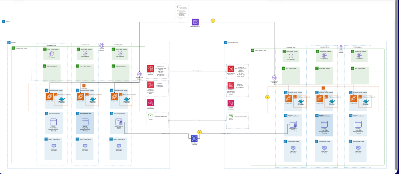
Figure 1: Multi-Region active-passive DR architecture for Terraform Enterprise on AWS. Note the bidirectional S3 replication arrows between Regions and the Amazon Route 53 health check that determines the active Region.
The example Terraform code used to configure and manage the core architecture components, along with the failover process can be found in this sample GitHub repository. You can use this code to test a similar pattern for your TFE workload.
Core architecture components
You can route traffic to the active Region with Amazon Route 53 DNS alias records pointing to an Elastic Load Balancing (ELB) Network Load Balancer. Alias records for ELB targets use a 60-second time-to-live (TTL), which limits how long DNS resolvers cache the record. Clients begin resolving to the DR Region within about a minute of failover rather than waiting for longer cached entries to expire.
In each Region, an Amazon Virtual Private Cloud (Amazon VPC) spans three Availability Zones, and Amazon EC2 Auto Scaling groups manage the TFE instances. To help minimize cost, Athenahealth scaled DR Region compute to zero during normal operations by setting the Auto Scaling group minimum capacity to 0.
For cross-Region database replication, Athenahealth uses Aurora PostgreSQL-Compatible global databases, which provide sub-second replication lag and managed failover. The primary cluster runs one writer and two readers across three Availability Zones. The secondary cluster maintains an inactive writer that’s ready for promotion.
You can replicate Terraform workspace state files bidirectionally between primary and DR Amazon S3 buckets with S3 cross-Region replication. This design supports failback without data resynchronization.
AWS Secrets Manager and AWS Key Management Service (AWS KMS) provide cross-Region credential and encryption key management. Two TFE-specific dependencies deserve attention when you design for multi-Region. First, the TFE encryption password protects the internal Vault unseal key and root token. DR instances configured with a different value cannot start or decrypt existing data, so verify that this secret is replicated to your DR Region and referenced by your DR launch configuration. Second, if you run TFE in Active/Active mode, external Redis holds the job queue and cache. Account for a Redis equivalent in the DR Region and decide what in-flight job loss is acceptable at failover. Amazon CloudWatch alarms in each Region monitor the TFE instances, Auto Scaling groups, and Aurora clusters in that Region. Detection of a primary Region impairment does not depend on the primary Region itself: the Amazon Route 53 health check shown in Figure 1 probes the TFE endpoint from a globally distributed checker fleet, and alerts publish through Amazon Simple Notification Service (Amazon SNS) topics in both Regions.
Failover process
The architecture uses a four-step failover sequence:
1. Activate DR Auto Scaling group (2-5 minutes). Scale from 0 to 1 instance and validate health checks. TFE exposes a health check endpoint (
/_health_check) that returns a 200 OK response when the application is running. The Network Load Balancer target group and the Route 53 health check probe this endpoint to determine instance health.2. Promote Aurora PostgreSQL-Compatible global database (~1 minute). Promote the DR writer. Complete this step before DNS failover shifts traffic to the DR Region, to help prevent both Regions from accepting writes simultaneously (known as a split-brain scenario in distributed databases).
3. Confirm Amazon Route 53 DNS failover (~60 seconds). The pre-configured Route 53 failover routing policy detects the unhealthy primary endpoint and routes traffic to the DR Region’s Network Load Balancer. This happens in the Route 53 data plane, with no record modifications at failover time.
[Important: Your failover process should not depend on control plane API calls during an event. Modifying Route 53 records to perform failover is a documented anti-pattern because the Route 53 control plane operates from a single Region. Athenahealth avoided this dependency with pre-configured health check-based failover routing. For manually initiated Region switches through a highly available data plane, consider Amazon Application Recovery Controller (ARC) Region switch, which Athenahealth plans to evaluate in a future phase.]
4. Scale out for production load (5-10 minutes). Increase Auto Scaling group capacity while monitoring Amazon CloudWatch.
Note: Run failover scripts from outside the primary Region—for example, from the DR Region, a separate management Region, or a CI/CD system that is not dependent on the primary Region. If your failover automation runs in the primary Region, it might be unreachable during the event you are trying to recover from.
The ordering between Aurora promotion and traffic shift is enforced procedurally rather than by an automated control. The DR Auto Scaling group runs at zero capacity during normal operations, so the DR endpoint cannot pass health checks until an operator executes the runbook, and the runbook sequences promotion ahead of scaling for traffic. For an orchestrated Region switch with explicit sequencing controls, consider Amazon Application Recovery Controller Region switch, which Athenahealth plans to evaluate in a future phase.
Total failover execution time: 12-14 minutes, meeting the established RTO.
Validating with AWS Fault Injection Service
With the multi-Region architecture now in place, we still needed to confirm it would work under real failure conditions. This is where AWS FIS was introduced into the DR workflow. AWS FIS injects controlled failures into your AWS environment that can be used to measure actual recovery times and catch configuration issues before an actual disruption. The following three phases show how Athenahealth validated their architecture, and you can apply the same approach to your TFE deployment as well.
Progressive experiment approach
Rather than testing full regional failover immediately, the team validated resilience in three progressive phases starting with individual compute failures, then database failover, and finally simulated S3 connectivity loss. Each phase built confidence in a specific layer of the architecture before combining them, and each surfaced issues that manual review had missed.
Phase A: Amazon EC2 and Auto Scaling group failure injection
Athenahealth hypothesized that if TFE instances were stopped or Amazon EC2 capacity became unavailable, the Auto Scaling group would launch replacement instances within five minutes without manual intervention. To test this, they ran the following AWS FIS actions: aws:ec2:stop-instances, aws:ec2:asg-insufficient-instance-capacity-error, and Auto Scaling group suspend and resume operations. You can use these same actions to validate your own Auto Scaling group recovery behavior.
The results confirmed the hypothesis. The Auto Scaling group detected failed instances and launched replacements within 2-3 minutes. Network Load Balancer health checks removed failed instances from rotation within 30 seconds.
These experiments also revealed an outdated Amazon Machine Image (AMI) reference in the DR Region’s Auto Scaling group launch template. Athenahealth builds custom AMIs and copies them to the DR Region, but the DR launch template still referenced an older version. This configuration drift only surfaced when AWS FIS forced the Auto Scaling group to launch new instances. If you’re running similar experiments, check the launch template AMI references in both Regions as part of your validation.
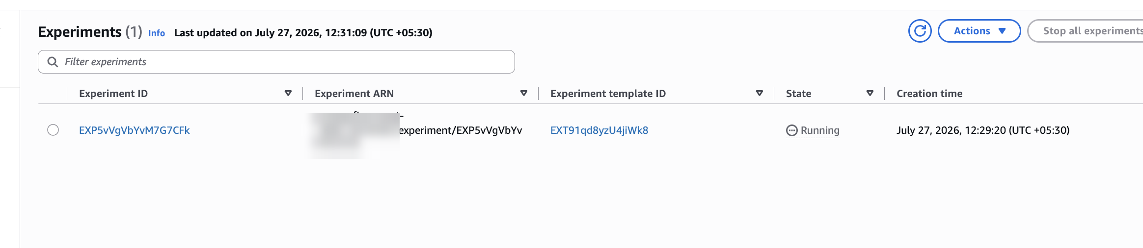
Figure 2. FIS experiments list showing experiment EXP5vVgVbYvM7G7CFk in Running state, created July 27, 2026 at 12:29:20 IST.
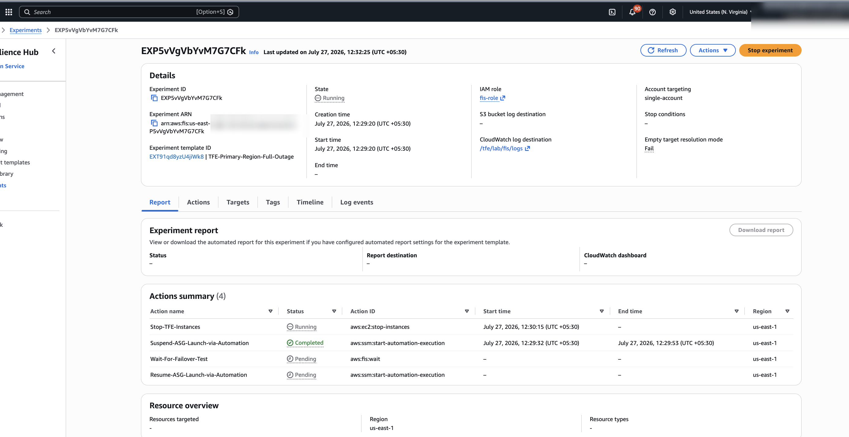
Figure 3. FIS experiment details showing template TFE-Primary-Region-Full-Outage, CloudWatch log destination /tfe/lab/fis/logs, Suspend-ASG completed, and Stop-TFE-Instances running.
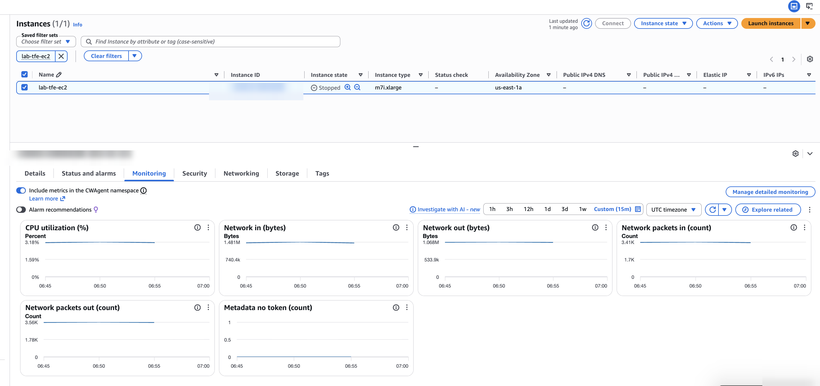
Figure 4. Primary EC2 instance in us-east-1 stopped after the FIS stop-instances action.
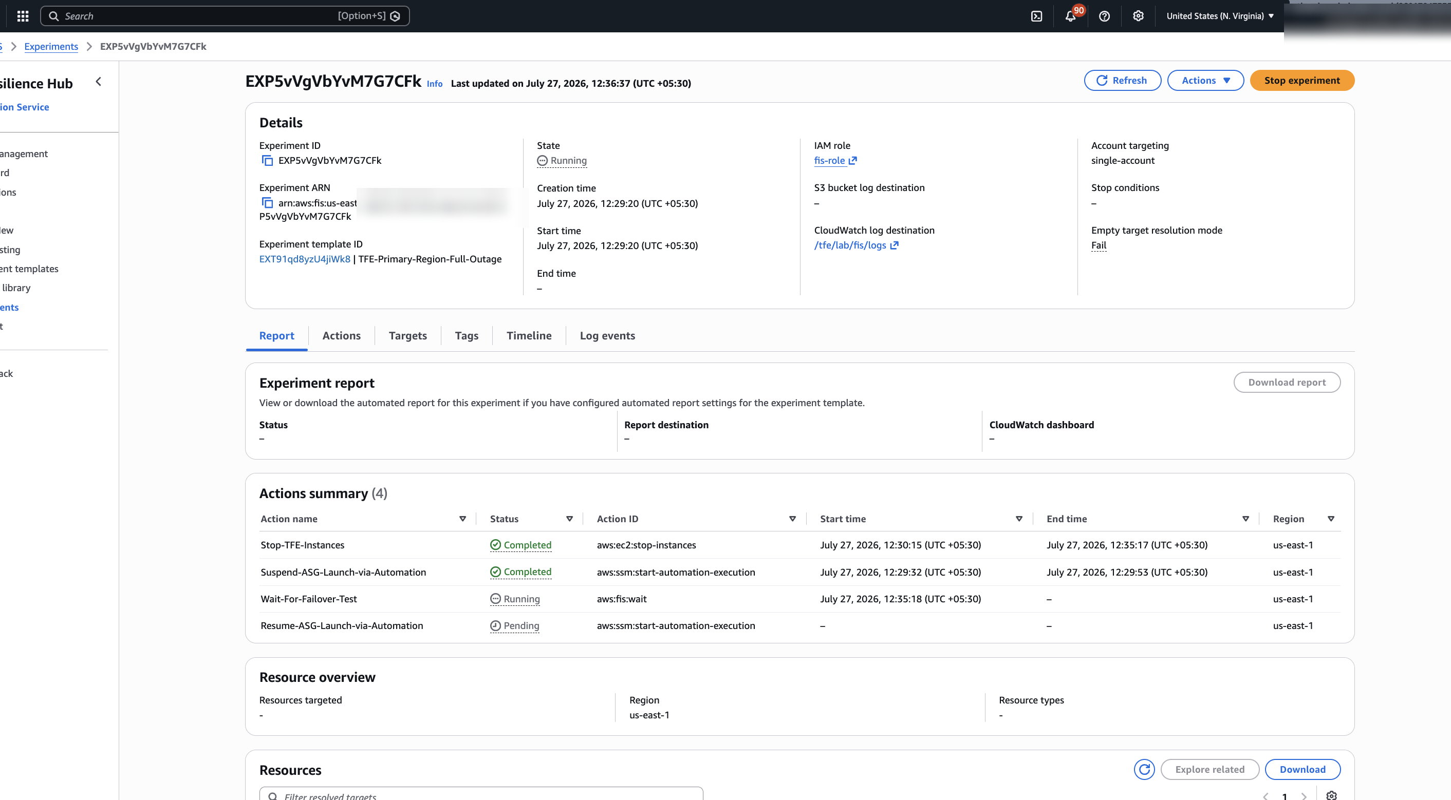
Figure 5. FIS action summary showing Stop-TFE-Instances completed at 12:35:17 IST and Wait-For-Failover-Test running.
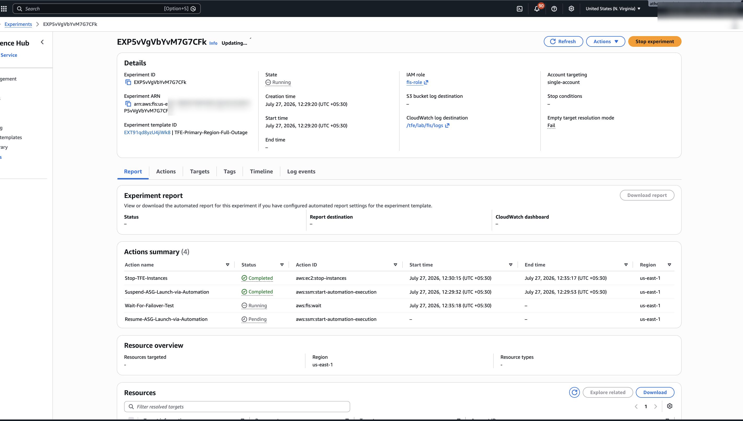
Figure 6. FIS experiment still running during the wait window, with stop action completed and resume action pending.
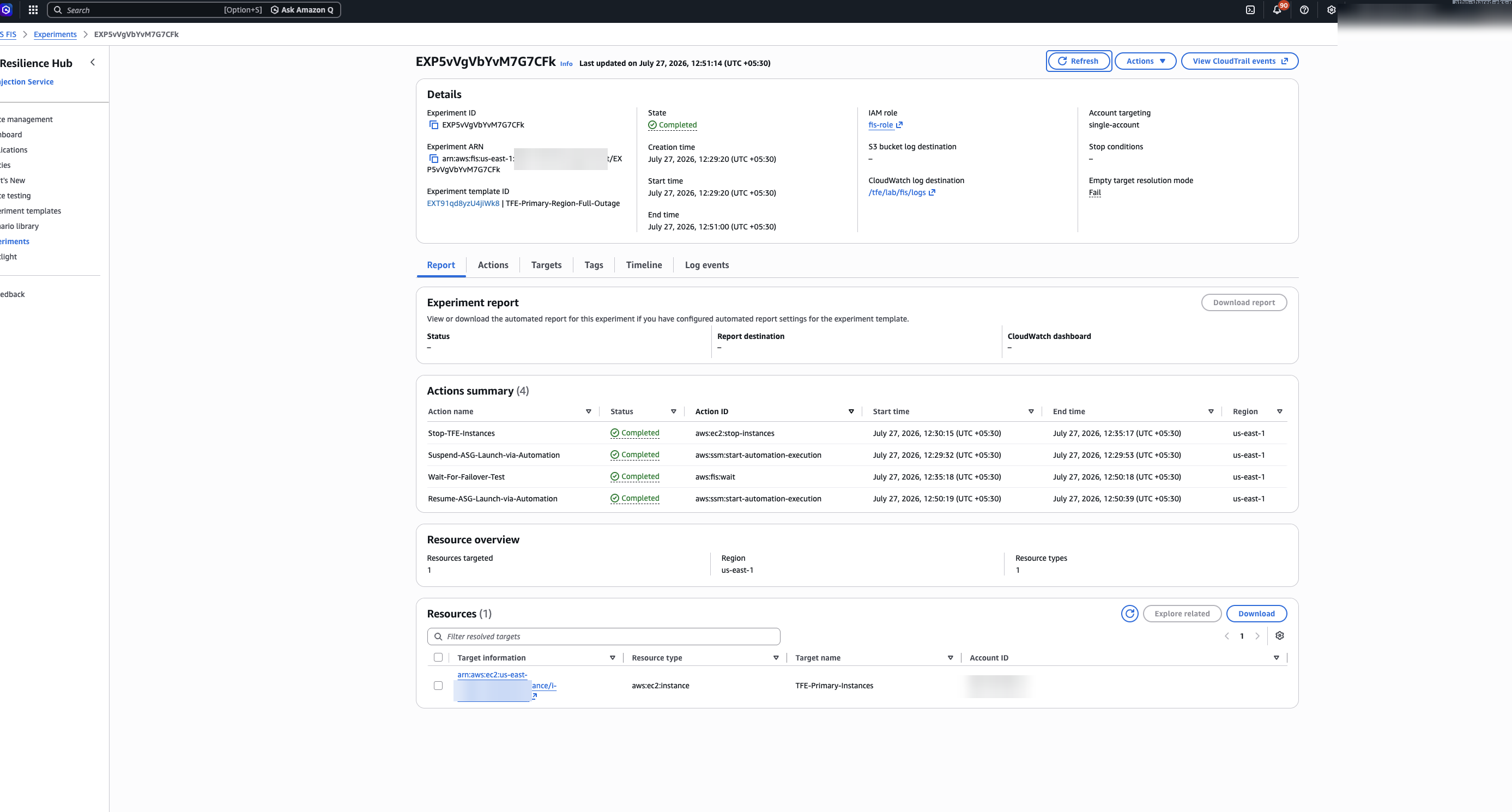
Figure 7. FIS experiment completed at 12:51:00 IST. All four actions show completed, including Resume-ASG-Launch-via-Automation.
Phase B: Aurora PostgreSQL-Compatible database cluster failover
Athenahealth hypothesized that if the Aurora PostgreSQL-Compatible global database cluster failed over, TFE would resume writes within one minute without manual intervention. To test this, they ran the aws:rds:failover-db-cluster AWS FIS action. The results confirmed the hypothesis for the database layer. Aurora promoted the secondary cluster’s writer in 58 seconds. During the promotion, TFE experienced approximately 15 seconds of write unavailability.
The Amazon Relational Database Service (Amazon RDS) Global Endpoint automatically redirected connections to the new writer. Athenahealth also discovered that the application layer did not meet the hypothesis. TFE connection pooling settings caused extended reconnection delays.
They reduced the connection pool timeout from 60 seconds to 10 seconds, which improved recovery time significantly. If you’re running TFE with Aurora PostgreSQL-Compatible, review your connection pool settings as part of your AWS FIS validation.
Note that this experiment exercised the coordinated failover path of Aurora, which requires the primary Region to be reachable to synchronize before promotion. During an actual event impairing the primary Region, you would instead use Aurora Global Database managed failover (the failover-global-cluster command with the --allow-data-loss option) or a manual detach-and-promote. These paths do not wait for replication to synchronize, so promotion timing differs and the RPO is bounded by the replication lag at the time of the event rather than zero. Treat the 58-second promotion and sub-second lag measured here as coordinated-path results, and plan unplanned-path expectations using the Aurora Global Database disaster recovery documentation.
Phase C: Amazon S3 connectivity disruption
Athenahealth hypothesized that if TFE lost connectivity to Amazon S3 in the primary Region, the DR Region bucket would hold current replicated state files without data loss. Testing this required a workaround, because AWS FIS doesn’t provide a direct action to disrupt Amazon S3 access. You can use the aws:network:disrupt-connectivity action instead to inject network ACL rules that block S3 traffic at the subnet level.
The aws:network:disrupt-connectivity action targets subnets, not S3 buckets directly. AWS FIS injects network ACL rules on compute private subnets, which blocks egress traffic to S3 service endpoints and simulates Regional S3 disruption for TFE instances in those subnets.
This experiment validates the S3 consumer, meaning TFE losing access to S3. It does not disrupt S3 cross-Region replication, because service-side replication between buckets does not traverse your subnet network ACLs. To test delayed or paused replication between Regions, use the Cross-Region: Connectivity scenario described in Next steps. Note that this approach assumes your TFE instances reach S3 over an in-VPC path, such as a gateway VPC endpoint, so the injected network ACL rules sit on the egress path to S3.
To configure this AWS FIS experiment, use the following template. Replace <your-tfe-compute-private-subnet-prefix> with your actual subnet name prefix, which you can find in the Amazon VPC console under Subnets.
The results confirmed the hypothesis for data durability. TFE detected S3 connectivity loss within 5 seconds. The DR Region S3 bucket contained replicated state files with less than 30 seconds of replication lag, and bidirectional replication prevented state file loss. The experiment also exposed a failure mode Athenahealth had not anticipated: the state file dependency issue detailed in the following section.
Combined experiment: primary Region impairment
After validating each layer individually, the team combined the faults into a single AWS FIS experiment template (shown in Figures 2-7). The experiment suspends the primary Region Auto Scaling group, stops the TFE instances, holds the faults in place during a wait window while the team executed the four-step failover runbook, and then resumes the Auto Scaling group. This end-to-end run validated the complete failover process under simultaneous compute impairment. The combined run surfaced no new failure modes beyond those found in the individual phases, which was itself the confirmation the team wanted.
Measuring recovery times
Across the three AWS FIS experiment phases, Amazon CloudWatch measured the following recovery times:
-
Amazon EC2 failure recovery: 2-3 minutes (automated Auto Scaling group replacement)
-
Aurora PostgreSQL-Compatible failover: 1-2 minutes (managed promotion)
-
Failover execution time: 12-14 minutes (operator-triggered four-step process)
-
Aurora replication lag: less than 1 second (99th percentile)
-
S3 replication lag: less than 30 seconds (99th percentile)
-
Data loss during failover: 0 bytes (across each experiment)
[Note: These measurements reflect controlled testing conditions. Aurora Global Database and S3 cross-Region replication are both asynchronous. During an actual event, writes committed within the replication lag window (sub-second for Aurora, up to 30 seconds for S3) may not yet be available in the DR Region. Plan for near-zero rather than zero data loss when setting RPO expectations.]
- Failback RTO: approximately 20 minutes (including approximately 5 minutes for Aurora PostgreSQL-Compatible global database re-establishment)
The 12-14 minutes measure failover execution time, from the operator triggering the runbook to full recovery. End-to-end recovery from event onset also includes detection time and the decision to fail over, so plan for a larger overall RTO.
Lesson learned: the state file dependency pitfall
Athenahealth first identified this risk during production failover and failback testing: their automation scripts depended on Terraform S3 state file outputs from both Regions. Subsequent AWS FIS experiments (Phase C) confirmed the severity. When S3 access is lost, those scripts fail entirely.
How the dependency breaks failover
Athenahealth’s failover and failback scripts automate the four-step process described earlier: scaling the Auto Scaling group in the target Region, promoting the Aurora global database writer, and verifying application health. An operator triggers them as part of the manual failover runbook, and they run from outside the primary Region. In their original form, the scripts retrieved infrastructure identifiers such as the Amazon RDS global cluster ID and Auto Scaling group name from state files stored in Amazon S3:
For an unplanned Regional impairment, add the --allow-data-loss option to this command to perform a managed failover instead of a switchover, because a switchover requires the primary Region to be healthy.
During a Regional service impairment, the primary Region’s S3 state file may be unreachable. The same applies in reverse during failback. The failover script tries to read the state file, S3 times out, and the script stops. This creates a circular dependency: you can’t run the failover without access to the infrastructure you’re trying to recover from.
How to remove the dependency
The underlying principle is to remove every recovery dependency on the Region you are recovering from. Failover automation must not read configuration from the control plane or data plane of the impaired Region. Athenahealth implemented this principle by hardcoding infrastructure identifiers directly in their failover scripts. You can obtain these values from your Terraform outputs during normal operations:
The trade-off is maintenance: hardcoded values require manual updates when infrastructure changes. Athenahealth addressed this with a CI/CD pipeline that compares hardcoded values against Terraform outputs and alerts on drift.
Hardcoding is one implementation of the principle. A Region-independent configuration source outside the primary Region achieves the same resilience with less drift risk, such as an AWS Systems Manager Parameter Store parameter replicated across Regions, an Amazon DynamoDB global table, or values committed to the repository that holds your failover scripts.
Testing failback
The state file dependency affected both failover and failback. Athenahealth validated failback by running full failover to DR, operating there for 30 minutes, then returning to primary. Bidirectional S3 replication prevented state file loss.
Collaboration model
If you’re planning a multi-Region DR project for TFE, consider a cross-functional approach. Athenahealth’s five-month engagement combined AWS resilience and AWS FIS expertise, HashiCorp TFE architecture knowledge, Terraform DR best practices, and HVD modules. This combination helped the customer reach production-validated DR faster than working independently. You can engage AWS Support or AWS Professional Services for similar guidance.
Conclusion
You can maintain infrastructure deployment capabilities during events that impact a single Region with a validated multi-Region DR architecture for TFE. This architecture achieved a validated RTO of 12-14 minutes and an RPO of less than 1 minute.
Multi-Region DR is not the right choice for every TFE deployment. Athenahealth chose this approach because TFE manages infrastructure for critical healthcare workloads. The October 2025 event showed that losing the ability to deploy during a regional event was a risk the business could not accept. Costs vary based on your configuration, but Athenahealth observed costs approximately 30-40% higher than their single-Region deployment, primarily from Aurora PostgreSQL-Compatible global database replication and S3 cross-Region replication. Weigh this cost against your own RTO and RPO requirements. For less critical workloads, a single-Region deployment with regular backups and a tested restore process may meet your needs.
Key takeaways
-
Give your infrastructure as code (IaC) tools the same resilience as production workloads. When your TFE deployment becomes unavailable during a Regional service event, you can’t deploy fixes or recover infrastructure.
-
Validate DR with controlled failure injection. AWS FIS experiments simulating real S3 connectivity loss exposed the state file circular dependency, a failure mode that only surfaces under actual disruption conditions.
-
Remove recovery dependencies on the Region you are recovering from. Dynamic lookups from state files tie failover to the infrastructure being recovered. Hardcoded identifiers or a Region-independent configuration source both work. Use drift detection to keep values current.
-
Test failback, not only failover. Without failback validation, you risk getting stuck in the DR Region or causing data loss when returning to primary.
-
Use subnet-level network disruption to simulate S3 connectivity disruption. The
aws:network:disrupt-connectivityaction targeting compute subnets simulates Regional S3 connectivity loss, which is the recommended approach because AWS FIS doesn’t offer a direct S3 disruption action.
Next steps
You can implement this solution in your environment with the following steps:
1. Run Phase A AWS FIS experiments on non-production TFE instances to validate Auto Scaling group recovery.
2. Review the HashiCorp’s Terraform Enterprise Validated Design module and DR guidance.
3. Establish your RTO and RPO targets before designing your Aurora replication strategy.
4. Create your first AWS FIS experiment to validate your DR architecture.
After you validate these three phases, extend your testing with additional AWS FIS scenarios. The AZ Availability: Power Interruption scenario validates recovery from the loss of an Availability Zone. The Cross-Region: Connectivity scenario simulates disrupted network connectivity between Regions, including paused S3 replication, which would delay state file replication to your DR Region.
If you need help designing or validating a multi-Region DR strategy, contact AWS Support or AWS Professional Services.
Cleanup
If you deploy this architecture for testing, delete the following resources in both Regions to avoid ongoing charges:
-
Aurora PostgreSQL-Compatible global database clusters.
-
Amazon S3 buckets with cross-Region replication.
-
Amazon EC2 instances in the DR Region Auto Scaling group.
If you used the sample GitHub repo to set up a test multi-Region TFE environment, verify that you also run terraform destroy to avoid any additional charges.
Resources:
-
AWS Fault Injection Service documentation.
-
Amazon Aurora PostgreSQL-Compatible global databases.
-
Amazon S3 cross-Region replication.
-
AWS Well-Architected Framework, Reliability Pillar.