Containers
Addressing IPv4 address exhaustion in Amazon EKS clusters using private NAT gateways
Introduction
The Amazon VPC Container Network Interface (CNI) plugin creates many advantages for pod networking when deployed on an Amazon Elastic Kubernetes Service (Amazon EKS) cluster. First, it lets us reuse proven, battle-tested Amazon Virtual Private Cloud (Amazon VPC) networking and security best practices for building Kubernetes clusters on AWS. This allows us to use VPC flow logs for troubleshooting and compliance auditing, apply VPC routing policies for traffic engineering, and apply security groups to enforce isolation and meet regulatory requirements. You get the raw performance of Amazon EC2 networking, with no additional overlay.
By default, Amazon VPC CNI plugin assigns each pod a routable IPv4 address from the VPC CIDR block so that each pod is treated as a first-class citizen in a VPC. This enables network communication between resources in the following scenarios: pod to pod on a single host, pod to pod on different hosts, pod to other AWS services, pod to an on-premises data center, and pod to the internet.
Customers typically use RFC1918 private IPv4 address ranges to set up Amazon VPCs, into which the workloads are deployed. In a large organization, it’s common for operations teams within a business unit to set up a separate, dedicated VPC to meet the needs of that business unit. If these private networks have to communicate with other such networks, either on-premises or in other VPCs, then they must ensure that these networks don’t have overlapping CIDR ranges. As a result, teams are often forced to use relatively smaller CIDR ranges for their VPCs to avoid potential overlaps. When such teams use container orchestration platforms like Amazon EKS to deploy microservices architecture, they frequently launch hundreds or thousands of workloads (pods) in their clusters.
When pods are assigned IPv4 addresses from the VPC CIDR range, this often leads to exhaustion of the limited number of IPv4 addresses available in their VPCs.
Exploring IPV4 address exhaustion solutions
Custom pod networking is one approach to alleviate IPv4 address exhaustion when deploying large-scale workloads to an Amazon EKS cluster. It lets us expand our VPCs by adding secondary IPv4 address ranges and then using these address ranges to assign IPv4 addresses to pods. Amazon recommends using CIDRs from the carrier grade-network address translation (CG-NAT) space (i.e., 100.64.0.0/10 or 198.19.0.0/16) because those are less likely to be used in a corporate setting than other RFC1918 ranges. However, this approach adds some complexity to the cluster configuration. There is still no guarantee that the use of CG-NAT address space will completely eliminate the likelihood of overlapping networks. If the custom networking option is not viable either, then we may have to use a different CNI plugin that uses a non-routable overlay network to assign IPv4 addresses to pods. We may to have to forgo all the advantages of using Amazon VPC networking for the pods in their cluster. The best long-term solution for the IPv4 exhaustion issue is to use IPv6. However, the decision to adopt IPv6 is typically done at the organization level as opposed to operations teams within individual business units.
The private NAT gateway solution
Amazon VPC now supports a private NAT Gateway, which was designed to allow instances in private subnets of a VPC to connect to other VPCs and on-premises networks with overlapping CIDR ranges without the use of an internet gateway. This functionality can be extended to work with Amazon EKS to solve the IP exhaustion problem. Private NAT gateways also address networking challenges that arise when workloads deployed to Amazon EKS clusters across multiple VPCs with overlapping CIDRs have to communicate with each other.
This post highlights the advantages of implementing a network architecture with a private NAT Gateway to deploy an Amazon EKS cluster. We demonstrate a use case where workloads deployed in an Amazon EKS cluster provisioned in a VPC (VPC-A) are made to communicate, using a private NAT gateway, with workloads deployed to another Amazon EKS cluster in a different VPC (VPC-B) with overlapping CIDR ranges.
Network architecture
The network architecture used in this implementation follows the recommendations under Enable communication between overlapping networks in Amazon VPC documentation. The routable address range (address ranges that cannot overlap) chosen here is 192.168.0.0/16 and the non-routable address range (address ranges that can overlap) is 100.64.0.0/16.
Let’s assume that an IP Address Management (IPAM) team has granted the routable address range 192.168.16.0/20 for setting up a VPC. The address range 100.64.0.0/16 is added as the secondary CIDR for this VPC. Subnets are set up across two Availability Zones (AZs). The following network diagram details various subnets in VPC-A, which is set up using the CloudFormation template from the Git repository. Here are the salient aspects of this network architecture:
- Two private subnets, each with 16 IP addresses (/28 block) are set up in the non-routable range. Per the recommendations under Subnet requirements and considerations, these subnets are used when creating an Amazon EKS cluster. The cross-account elastic network interfaces (ENIs) created by Amazon EKS to manage the communications between the Amazon EKS control plane and data plane are placed in these subnets.
- Two more private subnets, each with 4096 IP addresses (/20), are set up in non-routable range. Kubernetes worker nodes and pods are deployed to these subnets and will be assigned IP addresses from this range when using Amazon VPC CNI plugin. Note that the size of these subnets (/20) was picked as a representative example. These subnets may be deleted and recreated with a larger size, if necessary, making use of almost the full complement of addresses in the non-routable range.
- Two private subnets and two public subnets, each with 256 IP addresses (/24) are set up in the routable range. Again, the size of these subnets (/24) was picked as a representative example.
- A private NAT gateway is placed in the /24 routable private subnet in each AZ. These gateways route traffic from Amazon EKS resources (worker nodes and pods) in the respective AZ and is destined for other routable private networks, either on-premises or in other VPCs. Each private NAT gateway first performs source NAT on the requests originating from these resources before routing them to their destination.
- A public NAT gateway is placed in the /24 routable public subnet in each AZ and is associated with an internet gateway to enable resources in the Amazon EKS cluster to access resources on the internet.
- To enable traffic routing as described previously, the route tables for the subnets are set up as shown in the following tables (the presence of a Transit gateway in the route table entries will be discussed shortly). Note that the /28 subnets don’t have any routes to communicate with resources outside the VPC. These subnets are used to place only the Amazon EKS-managed cross-account ENI, which enables communication between the control plane and the kubelet on a worker node. Hence, just the local routes for communication within the VPC will suffice.
- The route table for the /20 private subnets in the non-routable range shows that traffic destined for the address range 192.168.32.0/20 is forwarded to a private NAT gateway. This address range corresponds to that of a second VPC (discussed in the following section) used in this implementation. In general, any traffic originating from these subnets that is destined for a private routable address range that does not belong to VPC-A, will be handled by the private NAT gateway in the respective AZ.


Figure 1. Network architecture with private NAT gateway
Cluster provisioning
Using the previous network architecture, we are now ready to provision an Amazon EKS cluster in the non-routable subnets of the VPC. This step is no different from provisioning an Amazon EKS cluster in a VPC that comprises a single routable address range with outbound access to the internet. This may be done using any one of the approaches outlined under Creating an Amazon EKS cluster.
The two non-routable /28 subnets are used for cluster creation. Subsequently, worker nodes are provisioned in the two non-routable /20 subnets. The current implementation uses AWS CloudFormation templates from the Git repository for both cluster creation and provisioning of a managed node group. The cluster has the default behavior where the API server endpoint is accessible from the internet. In this mode, Kubernetes API requests that originate from within the VPC (such as node to control plane communication) leave the VPC but not Amazon’s network. Per the route tables above, the /20 non-routable subnets (and hence the worker nodes deployed to them) have outbound access to the internet via a public NAT Gateway and thus have access to the cluster API server endpoint. The network architecture presented here works for clusters with private endpoint as well.
Next, let’s see how to allow communication between the above VPC (VPC-A) and another VPC (VPC-B) with the routable address range 192.168.32.0/20 and the non-routable address range 100.64.0.0/16. In VPC-B, we create an additional Amazon EKS cluster using the same network architecture as VPC-A. VPC peering connection can’t be used between VPCs with overlapping CIDRs. Hence, a transit gateway is deployed to enable communication between the two VPCs. The transit gateway is set up with transit gateway attachments to the two VPCs. The attachments are each assigned the /24 private routable subnets in the respective VPC.
Please refer to the Transit Gateway Guide for details about how to work with transit gateways.

Figure 2. Connecting VPCs with overlapping CIDR ranges using a transit gateway
When creating a VPC attachment for a transit gateway, the CIDR blocks of the VPC are propagated to the transit gateway route table by default. This includes the non-routable address ranges as well. To avoid this, default route propagation is turned off when creating the transit gateway. Static routes are added to the route table, as shown in Figure 2, after creating the gateway. The routes in the transit gateway route table, in conjunction with those in the route tables for both non-routable and routable private subnets in each VPC, allow resources in non-routable private subnets to access resources in the other VPC.
For a detailed walkthrough of network packet flow across VPCs using this type of network architecture, please refer to this post: How to solve Private IP exhaustion with Private NAT Solution.
Solution overview
We use the previous network architecture and demonstrate a real-world use case, which comprises the following components:
- An Amazon EKS cluster is deployed to the non-routable subnets in VPC-A.
- An HTTP web service is deployed to this cluster as a Kubernetes Deployment resource and is exposed to the internet over HTTP using an Application Load Balancer which is managed by an AWS Load Balancer Controller. To ensure that the load balancer is placed in the routable public subnets in VPC-A, those subnets have been assigned the tag kubernetes.io/role/elb=1. Alternatively, the subnets may be explicitly specified using the annotation alb.ingress.kubernetes.io/subnets set on the Ingress resource deployed in conjunction with the web service.
- An Amazon EKS cluster is deployed to the non-routable subnets in VPC-B.
- A TCP web service is deployed to the cluster in VPC-B as a Kubernetes Deployment and is exposed internally to other routable private networks over TCP/IP using a Network Load Balancer which is managed by an AWS Load Balancer Controller. This is done by setting the annotation beta.kubernetes.io/aws-load-balancer-type=external on the Service resource deployed. The AWS Load balancer controller provisions an internal NLB by default. The private routable subnets in the VPC have been assigned the tag kubernetes.io/role/internal-elb=1 and therefore, the internal load balancer is placed on those subnets.
- An Amazon Aurora PostgreSQL database is deployed to the private routable subnets in VPC-B.
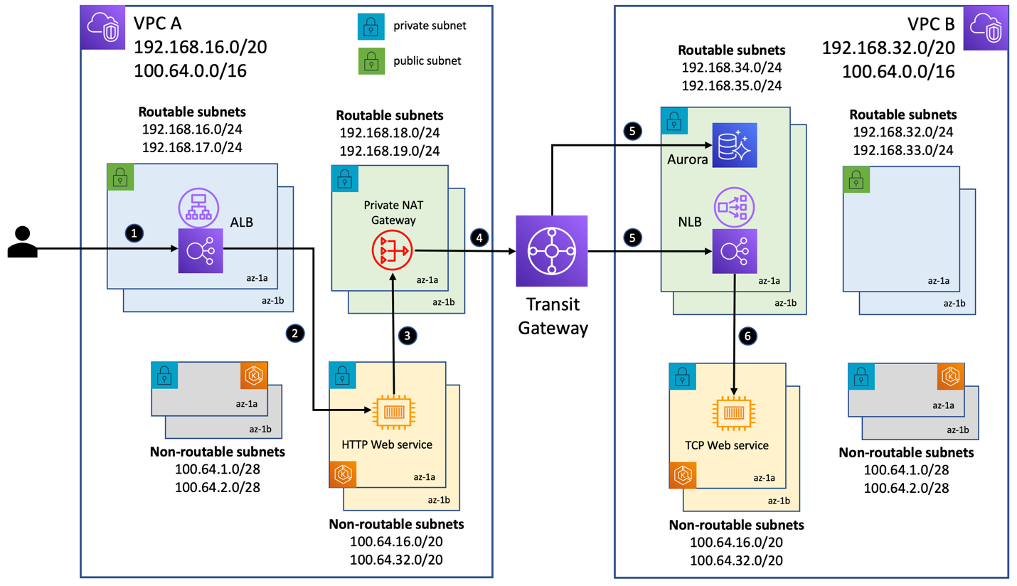
Figure 3. Solution architecture with two Amazon EKS clusters using overlapping CIDR ranges
The request-response scenario for the use case demonstrated here is as follows (referring to the numbered steps in Figure 3 above):
- Client makes a request to the API end points /data and /time exposed by the HTTP web service. Request is first sent to the internet-facing Application Load Balancer in VPC-A.
- The load balancer routes the request to one of the pods deployed in the non-routable subnets in VPC-A.
- Invoking the /data endpoint triggers a call from the web service in VPC-A to the Amazon Aurora database in VPC-B. Invoking the /time endpoint triggers a call to the internal Network Load Balancer in VPC-B. Both these components have a routable private IP address from an address range different from that of VPC-A. Hence, per the routes in the route table associated with the non-routable private subnets in VPC-A (refer to the table in Figure 1), the request from a pod is forwarded to the private NAT gateway in the corresponding AZ.
- The private NAT gateway will first source NAT the requests, setting their source IP address to its own routable IP address. Subsequently, the routes in the route table associated with the routable private subnets in VPC-A (refer to the table in Figure 1) dictate the next hop. In this use case, the requests are sent to the transit gateway.
- Depending on the destination IP, the transit gateway sends the request to the Amazon Aurora database instance or to the Network Load Balancer. This hop is dictated by the routes in the transit gateway route table.
- When the Network Load Balancer receives the request, it routes it to one of the pods deployed in the non-routable subnets in VPC-B.
The following diagram shows the output of invoking the end points of the HTTP web service using a custom Domain Name System (DNS) name for the internet-facing Application Load Balancer. Calls to the /data endpoint returns a JSON object retrieved from the Amazon Aurora database. Calls to the /time endpoint returns the current data/time returned by the TCP web service.

Source code
We have provided the complete set of deployment artifacts in the Git repository. In addition, the repository includes instructions for implementing the network architecture described in this post, as well as steps to deploy Amazon EKS clusters and sample workloads. Please review the network architecture and Amazon EKS cluster design with your internal security team before deploying to production. An Amazon Aurora PostgreSQL instance has been used in this implementation merely as a sample database workload to demonstrate connectivity to an AWS managed service from Amazon EKS workloads when using this network architecture. Please follow the Amazon RDS best practices guide for using the managed databases in production and follow the database user and access model as defined by your company.
Conclusion
In this post, we showed you a network design that enabled communication across Amazon EKS clusters deployed to VPCs with overlapping CIDRs. This architecture was enabled by private NAT gateways that allowed compute resources with private IP addresses from a non-routable address range to interact with resources with private IP addresses from a routable address range.
We also addressed the IPv4 address exhaustion issue for Amazon EKS customers using the Amazon VPC CNI plugin for pod networking and deploying thousands of pods. When VPCs have overlapping address ranges, we need to use a transit gateway. You should perform a thorough cost analysis based on AWS Transit Gateway pricing and assess whether the scale of your operations justifies the additional cost of using a transit gateway.
For use cases in which Amazon EKS resources in a VPC’s non-routable address range need to communicate with other VPCs that do not have overlapping address ranges, you have the option of using VPC Peering to interconnect such VPCs. This method could provide potential cost savings, because all data transit within an AZ via a VPC peering connection is now free.