Networking & Content Delivery
AWS Cloud WAN Routing Policy: Real-World Global Network Scenarios – Part 2
In Part 1, we introduced AWS Cloud WAN routing policies and showed how you can use fine-grained controls to influence route propagation and path selection across a global network. Each routing policy is built with three core components: 1) match conditions, that evaluate route prefixes or BGP attributes; 2) actions, that determine how matching routes are handled; and 3) directionality, that specifies whether the policy applies to inbound or outbound route propagation. These building blocks can be applied at the attachment, segment, or Region level.
In this post, we build on those concepts by exploring three real-world scenarios commonly seen in hybrid and multi-site environments. You’ll learn how to use AWS Cloud WAN routing policies to control routing during migration from AWS Transit Gateway environments, improve path selection across multiple AWS Direct Connect locations using local preference, and allow connectivity between networks with identical BGP Autonomous System Numbers (ASNs).
These patterns show how you can use AWS Cloud WAN as a centralized policy enforcement point to simplify routing control across your global network.
The scenarios described in this post are not an exhaustive list. AWS Cloud WAN routing policy supports additional match conditions and actions beyond what is covered here, so you can address routing challenges specific to your environment. For a full list of available match conditions and actions, see the AWS Cloud WAN routing policy documentation.
Prerequisites
This post is the second in a two-part series. We assume you have read Part 1: AWS Cloud WAN Routing Policy — Fine-grained controls for your global network, which covers the fundamentals of routing policy including match conditions, actions, directionality, and basic configuration workflows. We also assume familiarity with core AWS networking services such as Amazon Virtual Private Cloud (Amazon VPC), AWS Cloud WAN, AWS Direct Connect, and AWS Site-to-Site VPN, and the fundamentals of Border Gateway Protocol (BGP), including concepts such as AS-path, local preference, and community attributes. For additional background on AWS Cloud WAN hybrid connectivity patterns, we recommend reviewing Simplify global hybrid connectivity with AWS Cloud WAN and AWS Direct Connect integration.
Note: AWS Cloud WAN routing policies require core network policy version 2025.11 or later. Make sure your core network is running this version before implementing the configurations described in this post.
Scenario 1: Controlling route propagation from existing Transit Gateway environments
If you’re adopting AWS Cloud WAN, you might already operate an existing environment built on AWS Transit Gateway. During migration, you can connect these environments to AWS Cloud WAN to allow a phased transition rather than a single cutover.
A common requirement in these architectures is to control how AWS Cloud WAN propagates routes learned from Transit Gateway to other parts of the network, particularly on-premises environments connected through AWS Direct Connect or AWS Site-to-Site VPN.
The following diagram (Figure 1) illustrates how routes are learned and propagated within AWS Cloud WAN when no routing policy is applied. In this example, a Transit Gateway in the ap-southeast-2 Region is connected to an on-premises data center (DC1) through AWS Direct Connect. After this Transit Gateway is attached to AWS Cloud WAN, DC1 begins receiving duplicate routes. One set is propagated directly from the Transit Gateway. The second set comes from AWS Cloud WAN itself, which learns those same routes from the Transit Gateway route table attachment and redistributes them over Direct Connect to DC1. Without a routing policy in place, this route duplication can lead to inefficient or unpredictable routing behavior:
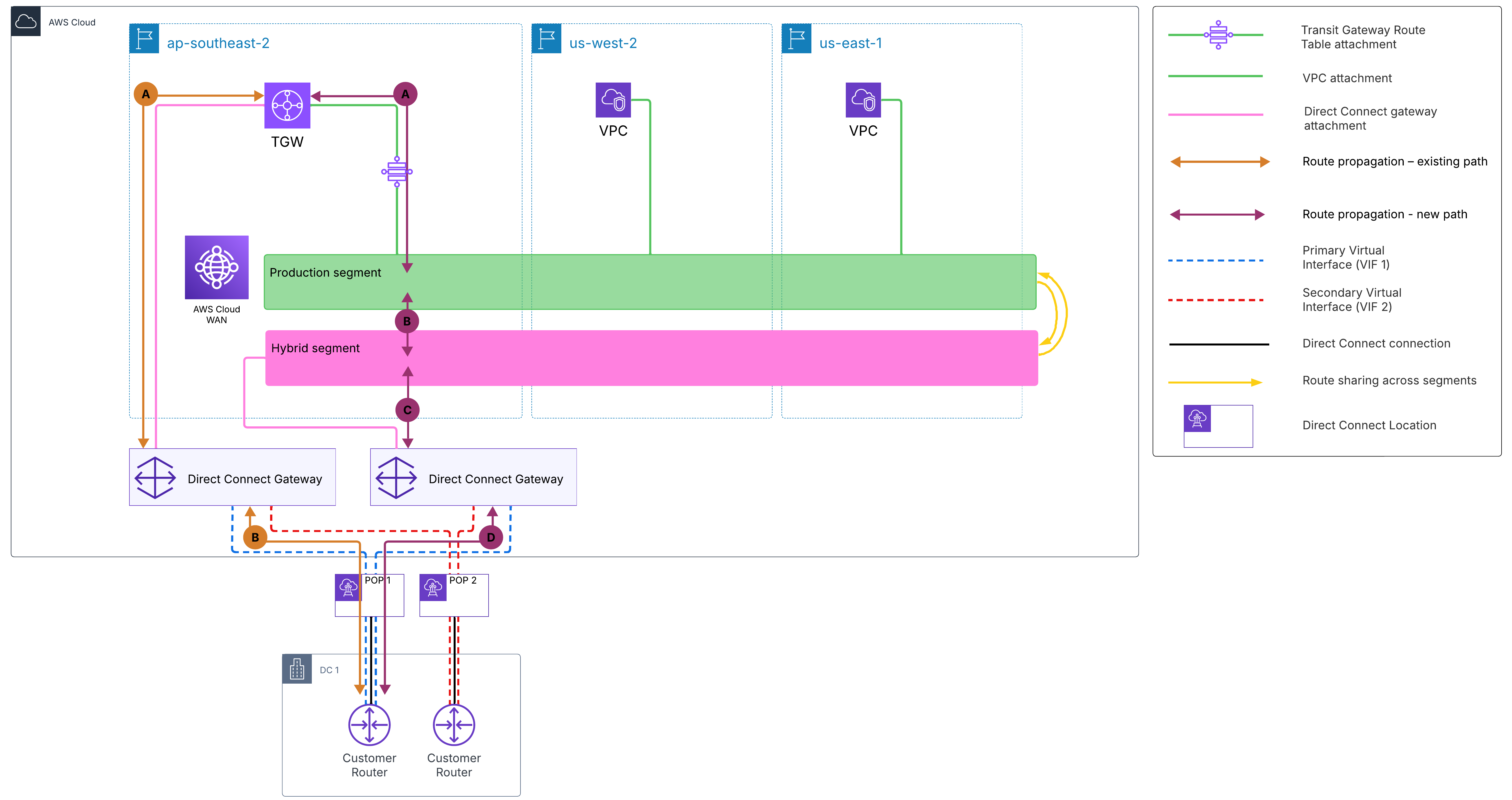
Figure 1: Route propagation behavior without routing policy
AWS Cloud WAN routing policies solve this through BGP community tagging and filtering, giving you precise control over which routes are advertised to on-premises environments.
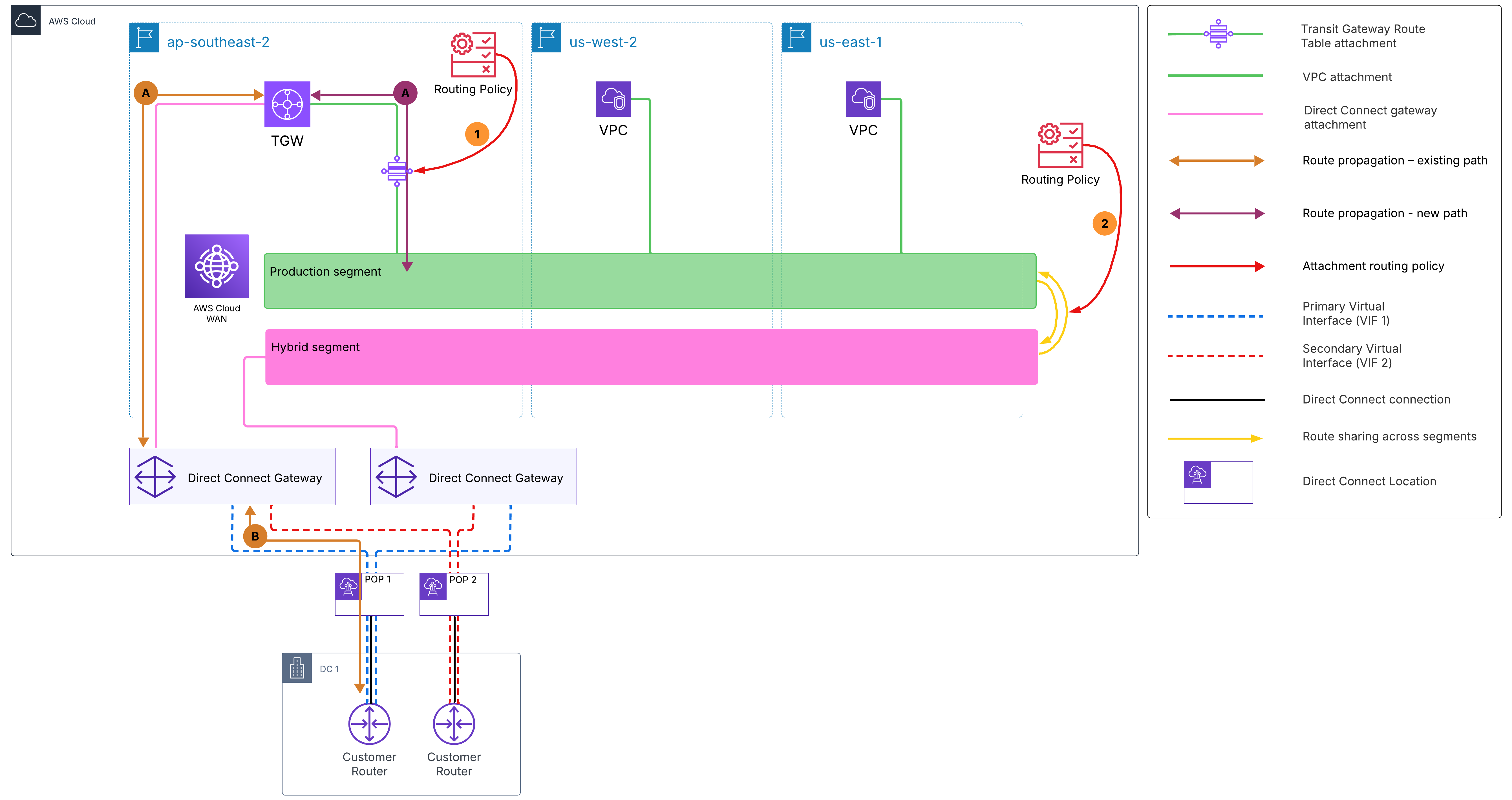
Figure 2: Route propagation behavior with routing policy applied
As shown in Figure 2, the Transit Gateway connects its production route table to the AWS Cloud WAN production segment. The routing policy operates in two steps. First, routes learned from the Transit Gateway route table attachment are tagged with a BGP community value (such as 65000:1). Second, this community tag is used as a filter when routes are shared from the production segment to the hybrid segment. Tagged routes are not advertised onward to the hybrid segment’s Direct Connect gateways (DXGWs).
As a result, on-premises data centers receive routes only from the Transit Gateway directly, removing duplicate advertisements and avoiding routing conflicts in architectures where the Transit Gateway remains connected to the same data centers.
Note: New VPCs attached directly to AWS Cloud WAN advertise their Classless Inter-Domain Routing (CIDR) blocks to the Transit Gateway so that existing VPCs behind the Transit Gateway can communicate with the VPCs on AWS Cloud WAN. However, these CIDR blocks are not advertised to on premises through the Transit Gateway’s Direct Connect gateway association unless they are included in the allowed prefixes list of that association. This prevents the Cloud WAN VPC routes from being advertised to DC1 over the Transit Gateway path, leaving the AWS Cloud WAN Direct Connect gateway as their only path to on premises.
How it works
Routes learned from the existing Transit Gateway enter the production segment and are tagged with community 65000:1 by the inbound policy on the attachment. Production VPCs and AWS Cloud WAN resources can reach Transit Gateway workloads normally. However, when production routes are shared with the hybrid segment, the outbound segment filtering policy matches on community tag 65000:1 and drops those routes. All other production routes (from VPCs) pass through to the hybrid segment and are advertised to on premises over Direct Connect. This prevents duplicate route advertisements to data centers that are still connected to the same Transit Gateway directly.
Step 1: Tag Transit Gateway routes with a community (inbound on Transit Gateway route table attachment)
Apply this inbound policy on the Transit Gateway route table attachment in AWS Cloud WAN. It matches all routes learned from the Transit Gateway and tags them with community 65000:1.
{
  "routing-policies": [
    {
      "routing-policy-number": 100,
      "routing-policy-name": "tagTgwRoutes",
      "routing-policy-description": "Tag routes learned from existing TGW with community 65000:1",
      "routing-policy-direction": "inbound",
      "routing-policy-rules": [
        {
          "rule-number": 10,
          "rule-definition": {
            "match-conditions": [
              {
                "type": "prefix-in-cidr",
                "value": "0.0.0.0/0"
              }
            ],
            "condition-logic": "and",
            "action": {
              "type": "add-community",
              "value": "65000:1"
            }
          }
        }
      ]
    }
  ]
}
Step 2: Filter tagged routes at segment sharing (prod → hybrid)
Apply this outbound policy when sharing routes from the production segment to the hybrid segment. It matches routes carrying community 65000:1 and drops them, preventing Transit Gateway originated routes from being propagated to the hybrid segment and on-premises DCs over Direct Connect. Routes that do not match the community value 65000:1 are implicitly allowed and continue to propagate normally. AWS Cloud WAN routing policy rules operate on a default-allow basis—only routes explicitly matched by a drop rule are filtered.
{
  "routing-policies": [
    {
      "routing-policy-number": 200,
      "routing-policy-name": "filterRoutesToHybrid",
      "routing-policy-description": "Drop TGW-originated routes (community 65000:1) when sharing prod to hybrid",
      "routing-policy-direction": "outbound",
      "routing-policy-rules": [
        {
          "rule-number": 10,
          "rule-definition": {
            "match-conditions": [
              {
                "type": "community-in-list",
                "value": "65000:1"
              }
            ],
            "condition-logic": "and",
            "action": {
              "type": "drop"
            }
          }
        }
      ]
    }
  ]
}
Step 3: Associate the policies to the distribution points
3.1 Apply the tagging policy to the Transit Gateway route table attachment using a routing policy label:
{
  "attachment-routing-policy-rules": [
    {
      "rule-number": 100,
      "conditions": [
        {
          "type": "routing-policy-label",
          "value": "TgwInbound"
        }
      ],
      "action": {
        "associate-routing-policies": [
          "tagTgwRoutes"
        ]
      }
    }
  ]
}
To complete the association, assign the routing-policy-label to the Transit Gateway route table attachment. You can do this when creating the attachment using the routing-policy-label parameter, or by editing an existing attachment in the AWS Cloud WAN console. For this scenario, assign the label TgwInbound to the Transit Gateway route table attachment.
3.2 Apply the filtering policy at the segment sharing level:
{
  "segment-actions": [
    {
      "action": "share",
      "mode": "attachment-route",
      "segment": "production",
      "share-with": [
        "hybrid"
      ],
      "routing-policy-names": [
        "filterRoutesToHybrid"
      ]
    }
  ]
}
Scenario 2: Improving path selection across multiple Direct Connect locations
If you have multiple on-premises locations, you likely advertise the same prefixes from multiple sites for resiliency. While this improves availability, it creates routing ambiguity where AWS Cloud WAN receives identical routes from multiple locations with no inherent preference. Without additional controls, this can lead to inefficient routing decisions if traffic is not steered appropriately.
Without a routing policy applied, AWS Cloud WAN relies on default routing behavior (longest prefix match) with no local preference or path steering. As shown in Figure 3, when AWS Cloud WAN learns the same prefix (for example, 10.2.0.0/16 originated by DC2) from all three DXGWs and sites simultaneously, it has no mechanism to prefer the direct path through DC2. As a result, traffic destined for DC2 can exit through DC1 or DC3 instead, resulting in unnecessary backbone traversal, higher latency, and increased cost.
Note: This scenario assumes that the on-premises data centers are interconnected through a backbone network, such as MPLS or AWS Direct Connect SiteLink, allowing traffic to traverse between sites during failover.
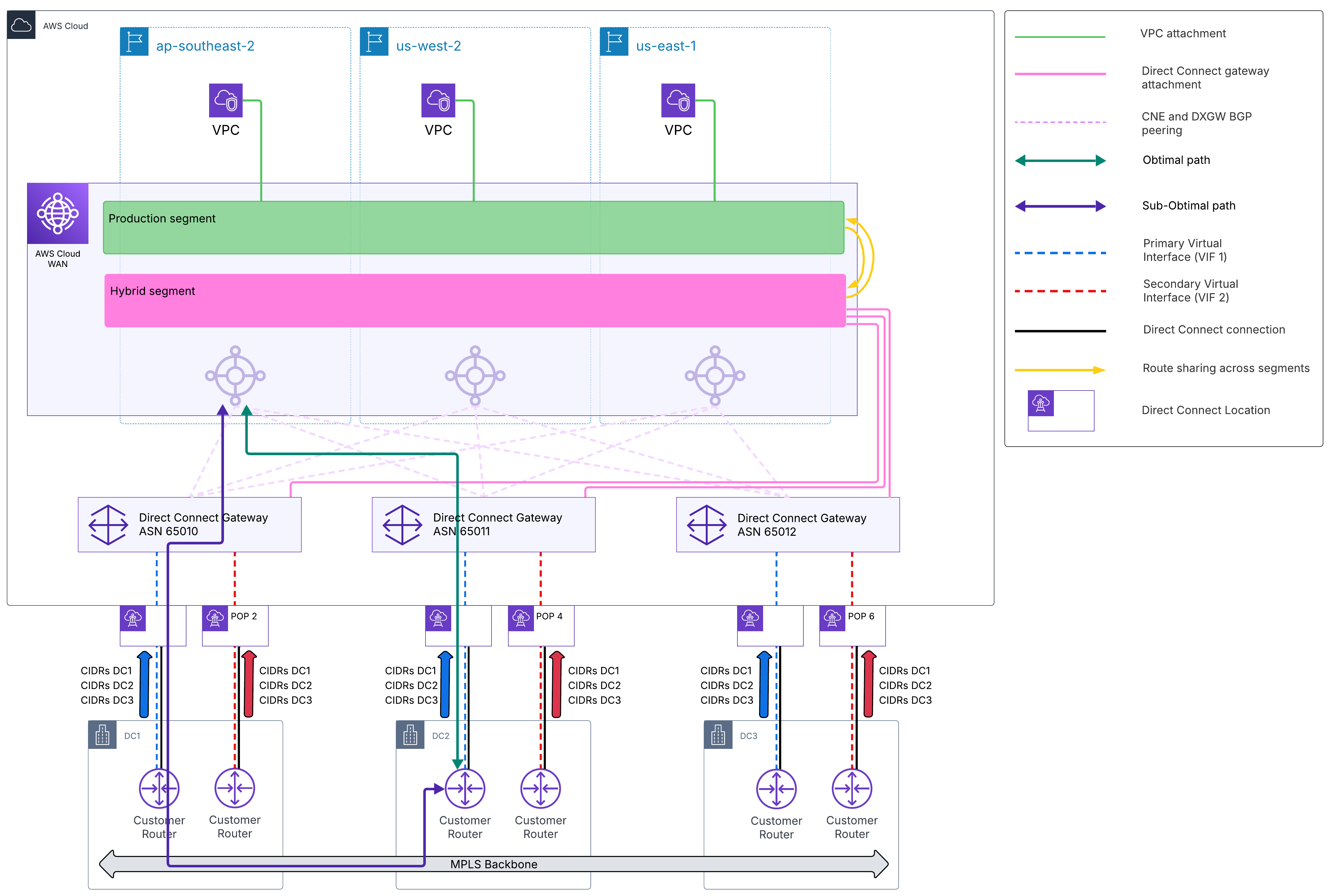
Figure 3: Route path selection without routing policy
AWS Cloud WAN routing policies provide centralized control over path selection using BGP attributes such as local preference. As shown in Figure 4, inbound routing policies applied to each DXGW attachment assign local preference values that steer traffic toward the originating data center, so that the most direct path is preferred.
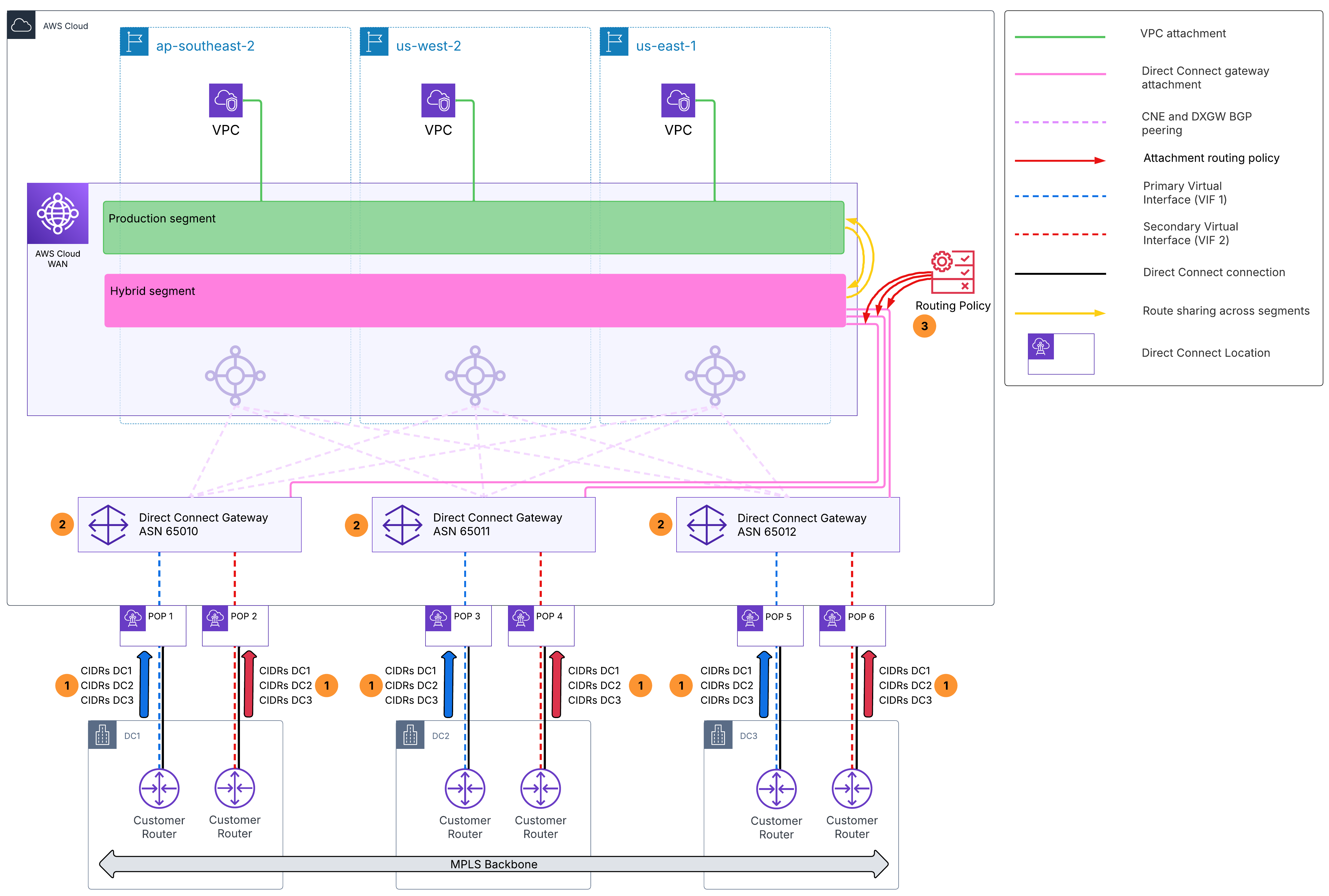
Figure 4: Route path selection with routing policy applied
In this scenario, each data center owns a specific set of prefixes: DC1 originates 10.1.0.0/16, DC2 originates 10.2.0.0/16, and DC3 originates 10.3.0.0/16. For resiliency, all three DCs advertise all three prefixes from their respective Direct Connect locations. Each DC connects through a dedicated DXGW: ASN 65010 for DC1, 65011 for DC2, and 65012 for DC3. AWS Cloud WAN learns the same routes from all three DXGWs and uses local preference to steer traffic for each prefix toward its owning DC. The other DCs serve as secondary and tertiary failover paths.
From the AWS Cloud WAN perspective, the path preference matrix for this scenario is:
| Prefix | 1st (local preference 300) | 2nd (LP 200) | 3rd (LP 100) |
|---|---|---|---|
| DC1: 10.1.0.0/16 | DXGW 65010 | DXGW 65011 | DXGW 65012 |
| DC2: 10.2.0.0/16 | DXGW 65011 | DXGW 65012 | DXGW 65010 |
| DC3: 10.3.0.0/16 | DXGW 65012 | DXGW 65011 | DXGW 65010 |
How it works
All three DCs advertise all three prefixes for resiliency, but each prefix belongs to a specific DC. When AWS Cloud WAN learns 10.1.0.0/16 from all three DXGWs, the routing policies assign it local preference 300 from DXGW 65010 (DC1, the owner), 200 from DXGW 65011 (DC2), and 100 from DXGW 65012 (DC3). AWS Cloud WAN selects the path with the highest local preference, steering traffic for 10.1.0.0/16 through DC1. If DC1’s Direct Connect path fails, traffic automatically falls back to DC2 (local preference 200), then DC3 (local preference 100). The same logic applies for DC2-owned prefixes (primary through DXGW 65011, secondary through 65012, tertiary through 65010) and DC3-owned prefixes (primary through DXGW 65012, secondary through 65011, tertiary through 65010).
At the DXGW level, an additional layer of path control is available through BGP communities on the VIFs. Each DXGW has two VIFs, one primary and one secondary, and community tags determine which VIF is preferred for outbound traffic: 7224:7300 for high preference and 7224:7100 for low preference. Alternatively, 7224:7200 can be applied to both VIFs for active-active ECMP load balancing.
With this configuration, AWS Cloud WAN and the DXGWs steer outbound traffic toward on premises using inbound route preferences. To achieve symmetric routing, on-premises devices should be configured to prefer the same paths for traffic flowing from on premises to AWS.
Note: Prefixes that do not match any of the three defined prefix lists pass through with no explicit local preference set, resulting in non-deterministic path selection across all three DXGWs. Make sure prefix lists are kept up to date as new prefixes are advertised from on premises.
Step 1: Define prefix lists for each data center
Create a separate prefix list for each data center, grouping the CIDRs that originate from that site. Prefix lists are created as Amazon VPC managed prefix lists and then associated with the core network using a prefix list alias. The alias is what the routing policies reference when matching prefixes. For example, create three managed prefix lists containing 10.1.0.0/16, 10.2.0.0/16, and 10.3.0.0/16 respectively, then associate them with the core network using the aliases dc1Prefixes, dc2Prefixes, and dc3Prefixes.
Note: The –max-entries parameter is required and defines the maximum number of entries the prefix list can hold. The value of 5 used here is arbitrary and can be adjusted based on the number of prefixes you plan to include.
aws ec2 create-managed-prefix-list --prefix-list-name dc1Prefixes --max-entries 5 --address-family IPv4 --entries Cidr=10.1.0.0/16
aws ec2 create-managed-prefix-list --prefix-list-name dc2Prefixes --max-entries 5 --address-family IPv4 --entries Cidr=10.2.0.0/16
aws ec2 create-managed-prefix-list --prefix-list-name dc3Prefixes --max-entries 5 --address-family IPv4 --entries Cidr=10.3.0.0/16
aws networkmanager create-core-network-prefix-list-association --core-network-id <core-network-id> --prefix-list-arn <dc1-prefix-list-arn> --prefix-list-alias dc1Prefixes
aws networkmanager create-core-network-prefix-list-association --core-network-id <core-network-id> --prefix-list-arn <dc2-prefix-list-arn> --prefix-list-alias dc2Prefixes
aws networkmanager create-core-network-prefix-list-association --core-network-id <core-network-id> --prefix-list-arn <dc3-prefix-list-arn> --prefix-list-alias dc3PrefixesStep 2: Define routing policies per DXGW attachment
Each DXGW gets its own inbound routing policy. The policy assigns local preference values to each prefix based on the path preference matrix, steering each prefix toward its originating DC with a deterministic failover order.
Policy for DXGW 65010 (DC1), primary for DC1, tertiary for DC2 and DC3:
{
  "routing-policies": [
    {
      "routing-policy-number": 100,
      "routing-policy-name": "pathPreferenceDxgw65010",
      "routing-policy-description": "DXGW 65010 (DC1): primary for DC1, tertiary for DC2, tertiary for DC3",
      "routing-policy-direction": "inbound",
      "routing-policy-rules": [
        {
          "rule-number": 10,
          "rule-definition": {
            "match-conditions": [
              {
                "type": "prefix-in-prefix-list",
                "value": "dc1Prefixes"
              }
            ],
            "condition-logic": "and",
            "action": {
              "type": "set-local-preference",
              "value": "300"
            }
          }
        },
        {
          "rule-number": 20,
          "rule-definition": {
            "match-conditions": [
              {
                "type": "prefix-in-prefix-list",
                "value": "dc2Prefixes"
              }
            ],
            "condition-logic": "and",
            "action": {
              "type": "set-local-preference",
              "value": "100"
            }
          }
        },
        {
          "rule-number": 30,
          "rule-definition": {
            "match-conditions": [
              {
                "type": "prefix-in-prefix-list",
                "value": "dc3Prefixes"
              }
            ],
            "condition-logic": "and",
            "action": {
              "type": "set-local-preference",
              "value": "100"
            }
          }
        }
      ]
    }
  ]
}
Policy for DXGW 65011 (DC2), primary for DC2, secondary for DC1 and DC3:
{
  "routing-policies": [
    {
      "routing-policy-number": 200,
      "routing-policy-name": "pathPreferenceDxgw65011",
      "routing-policy-description": "DXGW 65011 (DC2): secondary for DC1, primary for DC2, secondary for DC3",
      "routing-policy-direction": "inbound",
      "routing-policy-rules": [
        {
          "rule-number": 10,
          "rule-definition": {
            "match-conditions": [
              {
                "type": "prefix-in-prefix-list",
                "value": "dc1Prefixes"
              }
            ],
            "condition-logic": "and",
            "action": {
              "type": "set-local-preference",
              "value": "200"
            }
          }
        },
        {
          "rule-number": 20,
          "rule-definition": {
            "match-conditions": [
              {
                "type": "prefix-in-prefix-list",
                "value": "dc2Prefixes"
              }
            ],
            "condition-logic": "and",
            "action": {
              "type": "set-local-preference",
              "value": "300"
            }
          }
        },
        {
          "rule-number": 30,
          "rule-definition": {
            "match-conditions": [
              {
                "type": "prefix-in-prefix-list",
                "value": "dc3Prefixes"
              }
            ],
            "condition-logic": "and",
            "action": {
              "type": "set-local-preference",
              "value": "200"
            }
          }
        }
      ]
    }
  ]
}
Policy for DXGW 65012 (DC3), primary for DC3, secondary for DC2, tertiary for DC1:
{
  "routing-policies": [
    {
      "routing-policy-number": 300,
      "routing-policy-name": "pathPreferenceDxgw65012",
      "routing-policy-description": "DXGW 65012 (DC3): tertiary for DC1, secondary for DC2, primary for DC3",
      "routing-policy-direction": "inbound",
      "routing-policy-rules": [
        {
          "rule-number": 10,
          "rule-definition": {
            "match-conditions": [
              {
                "type": "prefix-in-prefix-list",
                "value": "dc1Prefixes"
              }
            ],
            "condition-logic": "and",
            "action": {
              "type": "set-local-preference",
              "value": "100"
            }
          }
        },
        {
          "rule-number": 20,
          "rule-definition": {
            "match-conditions": [
              {
                "type": "prefix-in-prefix-list",
                "value": "dc2Prefixes"
              }
            ],
            "condition-logic": "and",
            "action": {
              "type": "set-local-preference",
              "value": "200"
            }
          }
        },
        {
          "rule-number": 30,
          "rule-definition": {
            "match-conditions": [
              {
                "type": "prefix-in-prefix-list",
                "value": "dc3Prefixes"
              }
            ],
            "condition-logic": "and",
            "action": {
              "type": "set-local-preference",
              "value": "300"
            }
          }
        }
      ]
    }
  ]
}
Step 3: Associate the policies to the DXGW attachments
Map each routing policy to a routing-policy-label, then define attachment-routing-policy-rules that match attachments by their label and associate the corresponding routing policies. Assign the routing-policy-label to each attachment.
{
  "attachment-routing-policy-rules": [
    {
      "rule-number": 100,
      "conditions": [
        {
          "type": "routing-policy-label",
          "value": "dxgw65010inbound"
        }
      ],
      "action": {
        "associate-routing-policies": [
          "pathPreferenceDxgw65010"
        ]
      }
    },
    {
      "rule-number": 200,
      "conditions": [
        {
          "type": "routing-policy-label",
          "value": "dxgw65011inbound"
        }
      ],
      "action": {
        "associate-routing-policies": [
          "pathPreferenceDxgw65011"
        ]
      }
    },
    {
      "rule-number": 300,
      "conditions": [
        {
          "type": "routing-policy-label",
          "value": "dxgw65012inbound"
        }
      ],
      "action": {
        "associate-routing-policies": [
          "pathPreferenceDxgw65012"
        ]
      }
    }
  ]
}
Next, apply the corresponding routing-policy-label to each DXGW attachment using the routing-policy-label parameter or the console. For this scenario, assign the label dxgw65010inbound to the DXGW 65010 attachment, dxgw65011inbound to the DXGW 65011 attachment, and dxgw65012inbound to the DXGW 65012 attachment.
Scenario 3: Allowing communication between networks with identical ASNs
Enterprises building Wide Area Networks increasingly use AWS backbone infrastructure for global connectivity but often encounter overlapping private ASNs, whether from acquisitions, organic growth, or multi-site deployments using common default ASN values. When multiple sites use identical ASNs, BGP loop prevention rejects routes that contain a site’s own ASN in the AS-path, breaking end-to-end communication across the WAN.
In this scenario, two ASN conflicts prevent end-to-end communication. As shown in Figure 5, both DC1 and DC2 (A) use ASN 65000. When AWS Cloud WAN propagates routes between them, each site rejects the other’s routes because it sees its own ASN in the AS-path. This triggers BGP loop prevention.
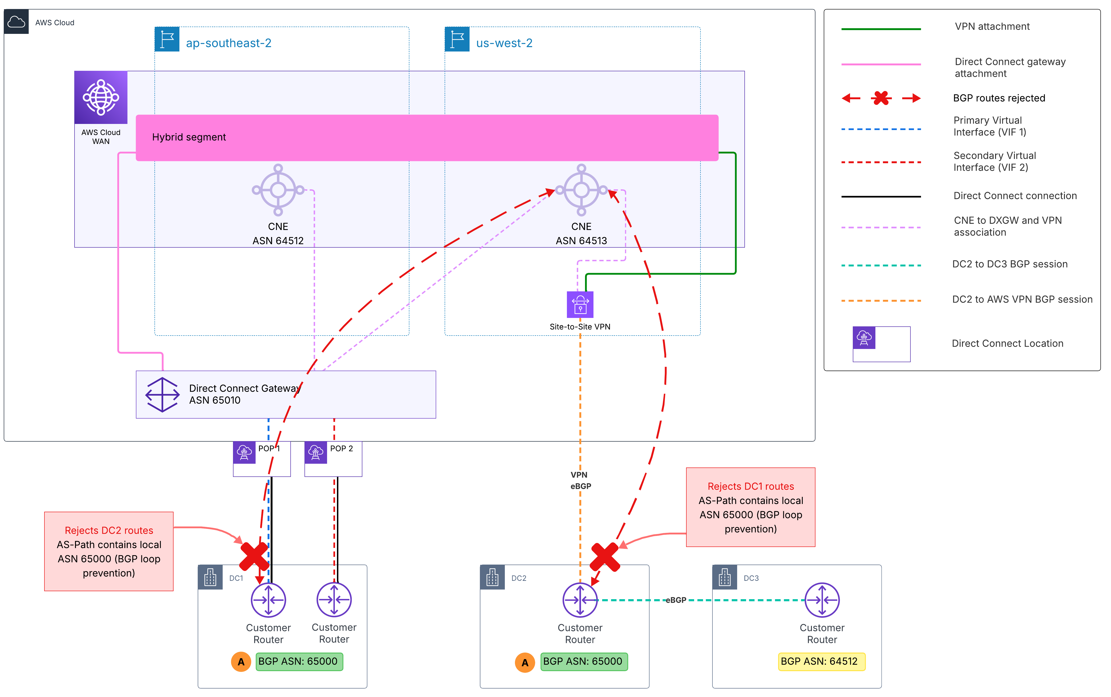
Figure 5: ASN conflict causing BGP loop prevention between DC1 and DC2
The second conflict (B), as shown in Figure 6, involves DC3 using ASN 64512, which conflicts with the AWS Cloud WAN core network edge (CNE) ASN in ap-southeast-2. This causes DC3’s routes to be dropped by the ap-southeast-2 CNE, and DC3 to drop routes from that CNE.
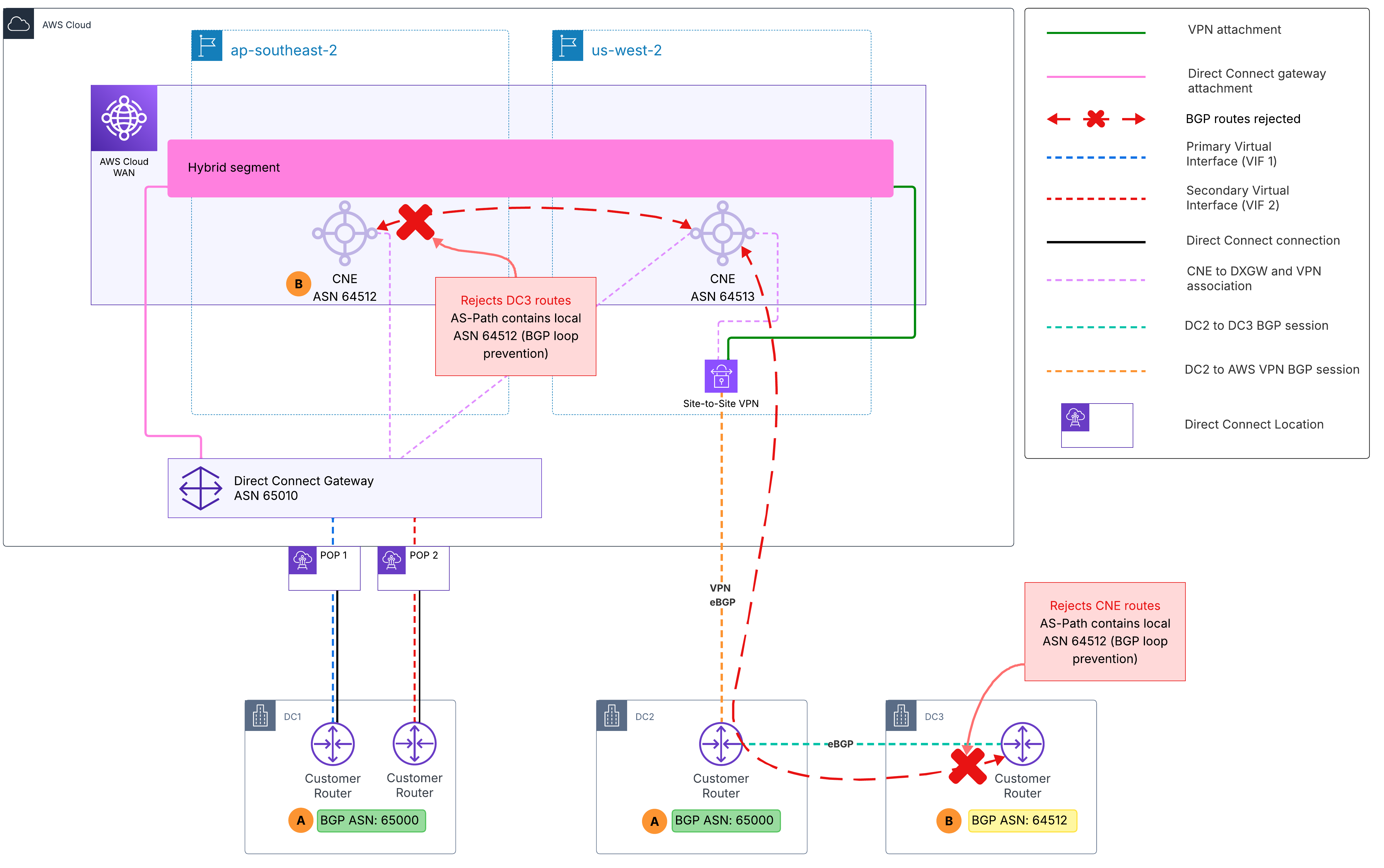
Figure 6: ASN conflict between DC3 and AWS Cloud WAN CNE blocking route propagation
Together, these two conflicts result in a complete loss of reachability across all three data centers.
AWS Cloud WAN routing policies address this with the replace-asn-list action, which replaces the entire AS-path with a specified set of ASNs, removing the conflicts that trigger loop prevention and restoring connectivity without requiring on-premises BGP renumbering.
As shown in Figure 7, the three data centers use AWS Cloud WAN as the central global backbone. DC1 connects through Direct Connect in ap-southeast-2 Region, DC2 connects through Site-to-Site VPN in us-west-2 Region, and DC3 reaches AWS Cloud WAN through DC2 over metro fiber. Inbound routing policies are applied at two attachment points: (1) the Direct Connect gateway attachment for DC1, and (2) the VPN attachment for DC2. Because DC3’s routes transit through DC2’s VPN attachment, the inbound policy at that attachment handles ASN replacement for both DC2 and DC3.

Figure 7: ASN replacement routing policy restoring connectivity across all three data centers
The following table summarizes the ASN replacements:
| Source | Original ASN | Replacement ASN | Reason |
|---|---|---|---|
| DC1 (Direct Connect) | 65000 | 65550 | Avoid loop detection at DC2 |
| DC2 (Site-to-Site VPN) | 65000 | 65551 | Avoid loop detection at DC1 |
| DC3 (via DC2 metro fiber) | 64512 | 65552 | Avoid conflict with ap-southeast-2 CNE ASN |
Important: AWS Cloud WAN core network edges (CNEs) perform BGP AS-path loop detection before inbound routing policies are evaluated. If a CNE receives a route carrying an ASN that matches its own, it drops the route before the replace-asn-list action can run. When planning your topology, make sure that on-premises routes do not carry an ASN matching the receiving CNE’s ASN.
How it works
The approach is to assign each site a distinct, non-conflicting replacement ASN so that no site ever sees its own ASN in propagated routes, and no route carries an ASN that conflicts with a CNE in your topology. When DC1 advertises routes to AWS Cloud WAN, the inbound policy on the Direct Connect gateway attachment replaces the entire AS-path with ASN 65550. These routes propagate through AWS Cloud WAN and reach DC2 with ASN 65550 in the AS-path instead of 65000, so DC2’s router accepts them without triggering loop detection.
When DC2 advertises routes, the inbound policy on the VPN attachment replaces the entire AS-path with ASN 65551. DC1 then receives these routes with ASN 65551 in the AS-path instead of 65000, preventing BGP loop detection and restoring bidirectional communication between DC1 and DC2.
For DC3, routes enter AWS Cloud WAN through DC2’s VPN attachment carrying both ASN 64512 (DC3) and ASN 65000 (DC2). The inbound policy replaces the entire AS-path with a single dedicated ASN (65552), removing both conflicting values in one operation. This allows DC3 prefixes to be accepted into the AWS Cloud WAN route table and advertised to DC1 and cloud resources.
All replacement ASNs (65550, 65551, and 65552) are selected outside the ASN range configured for the core network edges, as routing policy replacement values cannot overlap with AWS Cloud WAN CNE ASN ranges.
Step 1: Define inbound policy on DC1’s Direct Connect gateway attachment
This policy matches routes arriving from DC1 that contain ASN 65000 in the AS-path and replaces it with 65550. When these routes are propagated to DC2, the AS-path no longer contains 65000, so DC2’s router accepts them.
{
  "routing-policies": [
    {
      "routing-policy-name": "replaceasndc1",
      "routing-policy-description": "Replace ASN 65000 from DC1 with 65550 to avoid loop detection at DC2",
      "routing-policy-direction": "inbound",
      "routing-policy-number": 100,
      "routing-policy-rules": [
        {
          "rule-number": 10,
          "rule-definition": {
            "match-conditions": [
              {
                "type": "asn-in-as-path",
                "value": 65000
              }
            ],
            "condition-logic": "and",
            "action": {
              "type": "replace-asn-list",
              "value": [
                65550
              ]
            }
          }
        }
      ]
    }
  ]
}
Step 2: Define inbound policy on DC2’s VPN attachment
This policy uses two routing rules to resolve the ASN conflicts:
- Rule 10 replaces DC3’s ASN (64512) with 65552.
- Rule 20 replaces DC2’s ASN (65000) with 65551.
The order matters because routes from DC3 pass through DC2 and therefore carry both ASNs in the AS-path. Since replace-asn-list overwrites the entire AS-path, Rule 10 must run first so DC3 routes receive their dedicated replacement ASN (65552).
If Rule 20 runs first, it matches DC2’s ASN and replaces the entire AS-path with 65551. DC3 routes would still be accepted and connectivity would work, but they would appear indistinguishable from DC2 routes, making route tracking and troubleshooting more difficult.
{
  "routing-policies": [
    {
      "routing-policy-name": "replaceasndc2",
      "routing-policy-description": "Replace ASN 65000 from DC2 with 65551 and ASN 64512 from DC3 with 65552",
      "routing-policy-direction": "inbound",
      "routing-policy-number": 200,
      "routing-policy-rules": [
        {
          "rule-number": 10,
          "rule-definition": {
            "match-conditions": [
              {
                "type": "asn-in-as-path",
                "value": 64512
              }
            ],
            "condition-logic": "and",
            "action": {
              "type": "replace-asn-list",
              "value": [
                65552
              ]
            }
          }
        },
        {
          "rule-number": 20,
          "rule-definition": {
            "match-conditions": [
              {
                "type": "asn-in-as-path",
                "value": 65000
              }
            ],
            "condition-logic": "and",
            "action": {
              "type": "replace-asn-list",
              "value": [
                65551
              ]
            }
          }
        }
      ]
    }
  ]
}
Step 3: Associate the policies to the attachments
Associate each routing policy with an attachment by defining attachment-routing-policy-rules that match on routing-policy-labels. Tag each attachment with its designated routing-policy-label using the routing-policy-label parameter or the console.
{
  "attachment-routing-policy-rules": [
    {
      "rule-number": 100,
      "conditions": [
        {
          "type": "routing-policy-label",
          "value": "dc1inbound"
        }
      ],
      "action": {
        "associate-routing-policies": [
          "replaceasndc1"
        ]
      }
    },
    {
      "rule-number": 200,
      "conditions": [
        {
          "type": "routing-policy-label",
          "value": "dc2inbound"
        }
      ],
      "action": {
        "associate-routing-policies": [
          "replaceasndc2"
        ]
      }
    }
  ]
}
Finally, tag each attachment with its designated routing-policy-label using the routing-policy-label parameter or the console. For this scenario, assign the label dc1inbound to the DC1 Direct Connect gateway attachment and dc2inbound to the DC2 VPN attachment.
Things to Know
- When you create a Direct Connect gateway attachment to AWS Cloud WAN, you can choose the CNEs to which the DXGW connects. Because each CNE advertises only its local regional VPC routes to the DXGW, we recommend selecting all CNEs, as shown in Scenario 2, unless you have a specific reason to limit the association.
- IPv6 is supported. The same match conditions, actions, and policy structures apply to IPv6 prefixes (using ::/0 as the wildcard match). You can apply identical routing policy patterns to IPv6 route propagation across all scenarios described in this post.
- Deploying multiple Direct Connect gateways, as shown in Scenario 2, provides finer routing control than using a single Direct Connect gateway (DXGW). AWS Cloud WAN routing policy offers a broader set of BGP attribute controls than what is available at the VIF and DXGW level. By distributing on-premises connectivity across multiple DXGWs, you shift routing decisions to AWS Cloud WAN, where you have access to richer policy controls for traffic engineering.
- Rules within a routing policy are evaluated in order by rule-number. Only drop and allow are terminal actions that stop evaluation. Other actions, such as replace-asn-list, set-local-preference, and add-community, are non-terminal—evaluation continues through the remaining rules, and each modification carries forward. The replace-asn-list action overwrites the entire AS-path rather than substituting individual ASNs. As a result, a route modified by an earlier rule no longer carries its original ASNs for a later rule to match on. When a route can carry multiple ASNs, such as DC3’s routes transiting DC2 in Scenario 3, order your rules so the most specific match is applied first.
- AWS Cloud WAN performs BGP AS-path loop detection on a per-CNE basis, and this check runs before inbound routing policies are applied. If an incoming route’s AS-path contains the ASN of a CNE the attachment connects to, the route is rejected before any replace-asn-list policy can modify it (see Scenario 3 for a detailed example).
Cleanup
The routing policies described in this post are defined within the AWS Cloud WAN core network policy document and do not create standalone billable resources. To remove these configurations, take the following steps:
- Remove the routing-policy-label from each attachment by editing the attachment in the AWS Cloud WAN console or using the AWS CLI.
- Remove the attachment-routing-policy-rules and any segment-actions referencing the policies.
- Delete the routing policy definitions (tagTgwRoutes, filterRoutesToHybrid, pathPreferenceDxgw*, replaceasn*) from the routing-policies section of your core network policy.
- Submit a core network policy version update to apply the changes.
- If you created managed prefix lists for Scenario 2 and no longer need them, delete them using the AWS CLI or the AWS Management Console.
Conclusion
In this post, we explored three real-world scenarios that demonstrate how AWS Cloud WAN routing policies can solve common routing challenges in hybrid and multi-site environments. We showed how to control route propagation from Transit Gateway environments using community tagging and filtering, improve path selection across multiple DXGWs and Direct Connect locations using local preference, and resolve BGP ASN conflicts using AS-path replacement. Together with Part 1, which covered the fundamentals of routing policy configuration, these scenarios illustrate how you can use AWS Cloud WAN as a unified routing control layer for your global network. To get started, refer to the AWS Cloud WAN documentation.
About the authors

Jordan Rojas Garcia
Jordan is a Senior Network Specialist Solutions Architect in the Worldwide Specialist Organization at AWS. He began his career working on traditional data center networks before joining AWS in 2018. At AWS, he focuses on designing cloud networking solutions and provides guidance and best practices for building networks in the AWS Cloud. Outside of work, Jordan enjoys traveling, exploring new cuisines, hiking, and fueling his passion for driving vehicles with both two and four wheels.

Akeef Khan
Akeef Khan is a Solutions Architect at Amazon Web Services based in Sydney, Australia. He works with customers in the Cross-Industries segment, helping organisations in Retail and QSR adopt, operate, and scale on AWS. His area of depth is networking, and he is passionate about helping customers simplify their global network connectivity using AWS services. Outside of work, he enjoys exploring emerging technologies and continuous learning.