Networking & Content Delivery
Extending SD-WAN Segmentation into AWS Cloud WAN – Part 2
For organizations operating multi-tenant environments, regulated environments, or multiple business units, maintaining strict network segmentation between SD-WAN and AWS is essential for meeting security, compliance, and operational requirements.
This is Part 2 of the two-part series on extending SD-WAN segmentation into AWS Cloud WAN. In Part 1, the Generic Routing Encapsulation (GRE) based Connect attachment model to map SD-WAN Virtual Routing and Forwarding (VRF) instances to AWS Cloud WAN segments was explored.
This post walks through an alternative architecture using Tunnel-less Connect attachments to extend VRFs into AWS Cloud WAN without encapsulation or tunnelling overhead. This approach provides high-performance networking that simplifies operations while preserving network segmentation.
Compared with the GRE-based approach, Tunnel-less Connect offers several advantages:
- Higher performance: Supports up to 100 Gbps per Availability Zone, compared with up to 5 Gbps per GRE tunnel (up to 20 Gbps per attachment by using four Connect peers with Equal-Cost Multi-Path (ECMP)).
- No encapsulation: Eliminates GRE tunnels entirely – removing tunnel creation and maintenance overhead, allowing direct Border Gateway Protocol (BGP) peering with the AWS Cloud WAN Core Network Edge, and avoiding tunnel-specific failure scenarios such as Maximum Transmission Unit (MTU) issues or encapsulation mismatches.
This model introduces a key architectural consideration: each VRF/Segment requires a dedicated Elastic Network Interface (ENI) deployed in a separate VPC. This is due to the underlying Transport VPC attachment (functioning as the underlay network) and Tunnel-less Connect attachment (functioning as the overlay network) must be associated with the same AWS Cloud WAN segment. Factors such as instance type selection, ENI capacity, and cost planning become key elements of the design process. This post walks through the architecture, configuration steps, and design trade-offs to help you implement this model effectively.
Model 2: Tunnel-less Connect with Multi-VPC ENIs
Architecture Overview
This model combines AWS Cloud WAN Tunnel-less Connect with Multi-VPC Elastic Network Interfaces (X-ENIs).
A key requirement of Tunnel-less Connect is that the VPC attachment (transport/underlay) and the Connect attachment (overlay) must associate to the same AWS Cloud WAN segment. This is what makes X-ENIs essential to the design.
An X-ENI allows an Elastic Network Interface created in one VPC to be attached to an EC2 instance in another VPC, provided both are in the same Availability Zone and the same AWS account.
The architecture uses the following components:
- A Transport VPC for the SD-WAN appliance, which is attached to AWS Cloud WAN and associated to the Transport Segment for management traffic. The Core Network Edge VPC attachment deployed in the same subnet as the SD-WAN appliance to enable seamless integration with direct reachability.
- A Data Plane VPC for each VRF you want to extend. Each VPC contains one X-ENI per Availability Zone in the same Availability Zone as the SD-WAN appliance, attached to the SD-WAN appliance and mapped to a specific VRF.
- Each Data Plane VPC attached to AWS Cloud WAN and associated with the corresponding segment. This VPC attachment acts as the transport underlay for a Tunnel-less Connect attachment, which is associated with the same segment.
- Connect peers configured between each X-ENI and the AWS Cloud WAN Core Network Edge using addresses from an Inside CIDR block allocated to the Core Network. This enables dynamic BGP route exchange between SD-WAN VRFs and AWS Cloud WAN segments
This results in a 1:1 mapping between SD-WAN VRFs and AWS Cloud WAN segments, supporting strict network isolation and segmentation.
Architecture Diagram
Figure 1 illustrates how Multi-VPC ENIs associated to the SD-WAN virtual appliance extends network segmentation to AWS Cloud WAN using Tunnel-less Connect attachments, mapping multiple VRFs to distinct AWS Cloud WAN segments. The diagram is conceptual and shows a single Availability Zone for simplicity; however, we recommend a multi-AZ deployment for high-availability. For large-scale global networks, we recommend using multiple AWS Regions for efficient routing.
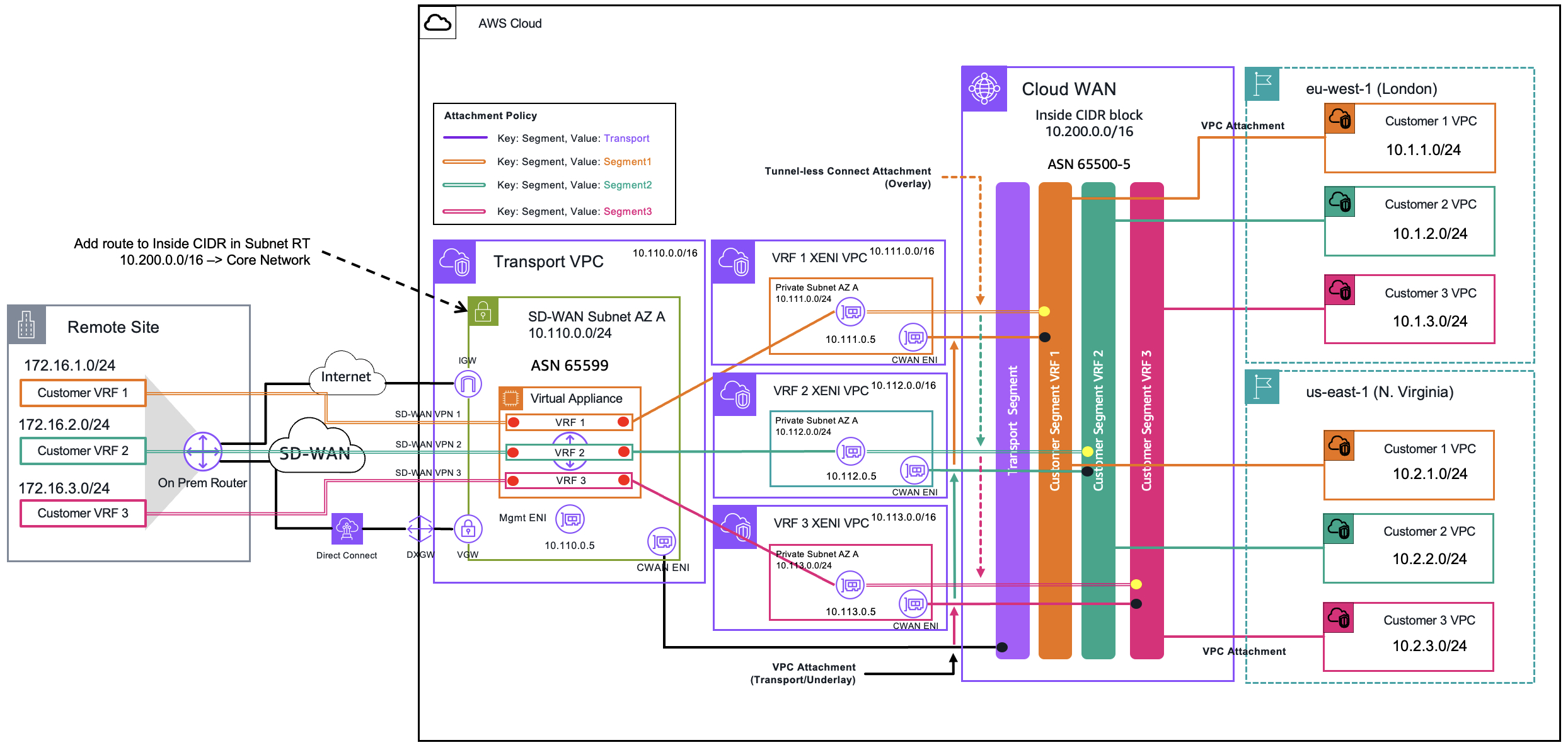
Figure 1 – Architecture Diagram of Tunnel-less Connect with X-ENIs
Prerequisites
This post focuses on connectivity between the SD-WAN appliance and AWS Cloud WAN. It does not cover the AWS Cloud WAN Core Network or SD-WAN appliance deployment. The following prerequisites are assumed:
- The AWS Cloud WAN Core Network is deployed with the required segments, Inside CIDR block, and attachment policies configured. For guidance on configuring the Inside CIDR block or attachment policies, see the example steps in Part 1 of this series.
- Source/destination checks are enabled by default. You must disable source/destination checks on all data plane interfaces of the appliance.
- The SD-WAN appliance is deployed in a Transport VPC according to the vendor’s recommendations. Deploy the SD-WAN appliances across multiple Availability Zones within a given Region for high availability. For large-scale global networks, use multiple AWS Regions for efficient routing.
- The SD-WAN appliance has connectivity to on-premises sites over the public internet through the AWS Internet Gateway, or over AWS Direct Connect.
- You have identified the EC2 instance type for your SD-WAN appliance and confirmed it supports the number of ENIs required for your deployment, including capacity for the future growth. Consult the AWS documentation on ENI quotas per instance type to plan accordingly.
Deployment Steps
Step 1 – Create the Data Plane VPCs, Subnets, and X-ENIs
Create the VPC:
- In the Amazon VPC Console, select Create VPC.
- Select VPC only
- Give the VPC a name that represents the VRF you are extending
- Allocate a unique IPv4 CIDR block (and optionally IPv6)
- Select the type of Tenancy and the level of VPC encryption control
- Select Create VPC
Repeat this step for every VRF you want to extend. There should be a 1:1 mapping between a VRF and a Data Plane VPC
For example, for three VRFs you should have three VPCs:
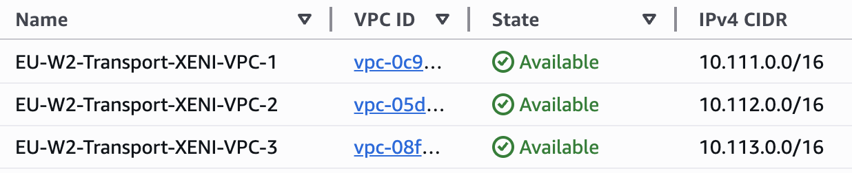
Figure 2 – Three Data Plane VPCs, representing three VRFs
Create the Subnets:
- When the VPC is in an available state, on the left navigation pane of the Amazon VPC Console, select Subnets
- Select Create subnet
- Select the VPC created in the previous step
- Give the Subnet a name and select the Availability Zone. This must be the same Availability Zone as your SD-WAN appliance.
- Provide an IPv4 subnet CIDR block (and/or IPv6 if configured on the VPC)
- Select Create subnet
Create one subnet per Availability Zone in each Data Plane VPC, where an SD-WAN appliance is deployed.
Create the X-ENI:
- In the Amazon EC2 Console, navigate to Network Interfaces in the left navigation pane.
- Select Create network interface.
- Select the Subnet, and the Interface type. By default, this will be ENA.
- Auto-assign a private IPv4 address or provide one manually. A custom IP is strongly recommended for consistent addressing across ENIs.
- Select Create network interface.
Repeat for each Availability Zone and VRF
Note: If you are manually providing an IP, the first four addresses and last address in the subnet’s CIDR block are reserved.
In this example, three VRFs are being extended for an SD-WAN appliance in AZ-A:
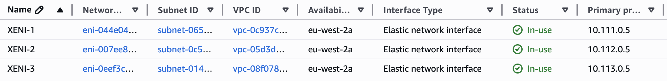
Figure 3 – Three Elastic Network Interfaces in AZ-A for SD-WAN Appliance
Note: Source/destination checks are enabled by default. You must disable source/destination checks on all data plane interfaces of the appliance.
Step 2 – Attach the Data Plane VPCs to AWS Cloud WAN and Configure VPC Route Tables
Create the VPC (Transport) Attachment:
Note: If AWS Cloud WAN is deployed in a separate AWS Account from the SD-WAN appliance, you must first share AWS Cloud WAN using AWS Resource Access Manager (RAM). If they are in separate AWS Accounts, perform the following steps in the AWS Account containing the SD-WAN appliance(s).
In the AWS Cloud WAN Console, create a new attachment with Attachment Type set to VPC. Select the Data Plane VPC and specify the subnet(s) where the Core Network Edge Attachment (ENIs) should be deployed. It is recommended to use the same subnet as the X-ENI for seamless integration and direct reachability.
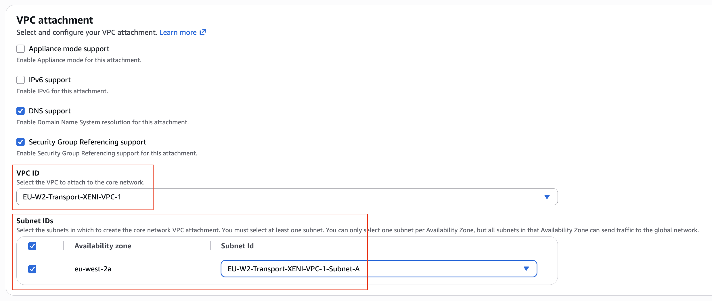
Figure 4 – VPC (Transport) attachment for Data Plane VPC 1
Select all Subnets / Availability Zones where you have deployed the X-ENIs.
Apply a tag to the attachment to enable automatic segment association (the tag-based attachment policy rule must already exist in your AWS Cloud WAN policy). If not configured, manually associate the attachment to the segment. If AWS Cloud WAN is deployed in a separate AWS Account from the SD-WAN appliance, you must perform the manual association from the AWS Cloud WAN administrative AWS Account.
This VPC attachment must be associated with the AWS Cloud WAN segment that represents the corresponding VRF.
Repeat for each Data Plane VPC representing each VRF.
Configure the VPC Route Table:
- In the Amazon VPC Console, select Route tables in the left navigation pane
- Select the Main route table associated with the VPC representing the VRF. You may optionally use a custom route table with explicit subnet associations.
- Select the Routes tab > Edit routes > Add route
- Enter the Inside CIDR allocated to your Core Network Edge, select the Target as Core Network, and choose your AWS Cloud WAN Core Network Attachment. This is to ensure there is a route to AWS Cloud WAN for BGP peering establishment.
- Select Save changes
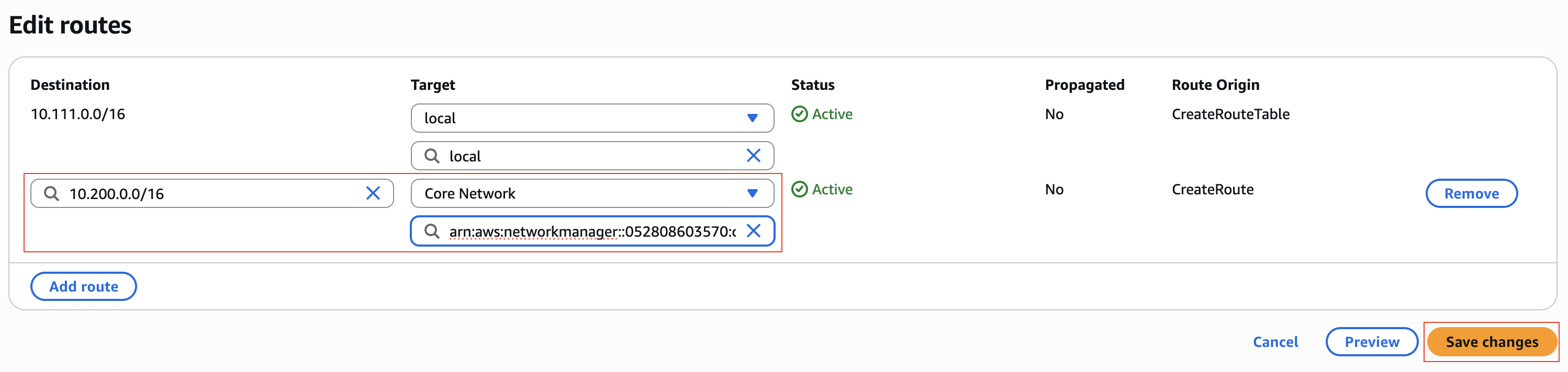
Figure 5 – Adding CNE Inside CIDR Route for X-ENI Subne
Note: It is recommended to deploy the X-ENI and Core Network Edge ENI in the same subnet. If they are in different subnets, you must also add routes on the Data Plane VPC route table for any prefixes the Core Network Edge advertises (for example, 10.0.0.0/8). A supernet route can cover multiple advertised prefixes.
Step 3 – Attach the X-ENI to the SD-WAN Appliance
In the Amazon EC2 Console, navigate to your SD-WAN appliance and select the instance.
- Choose Actions > Networking > Attach network interface
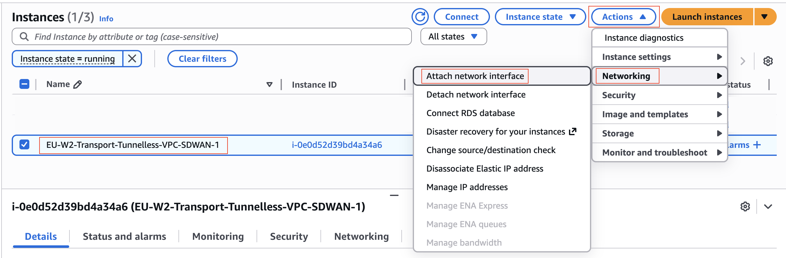 Figure 6 – Attach Network Interface using the Amazon EC2 Console
- Select the VPC in which the X-ENI representing the target VRF resides, choose the X-ENI, and attach it to the SD-WAN appliance.
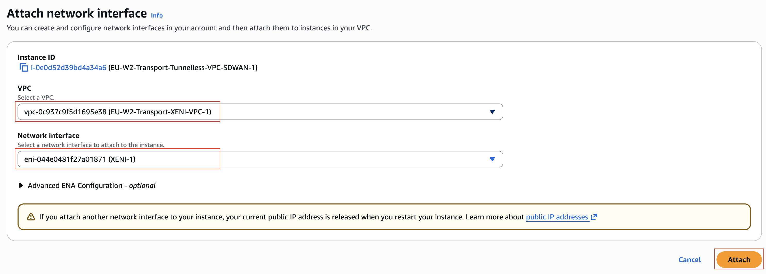
Figure 7 – Attach Network Interface to SD-WAN Appliance
Repeat this process for each additional X-ENI representing other VRFs for a given Availability Zone.
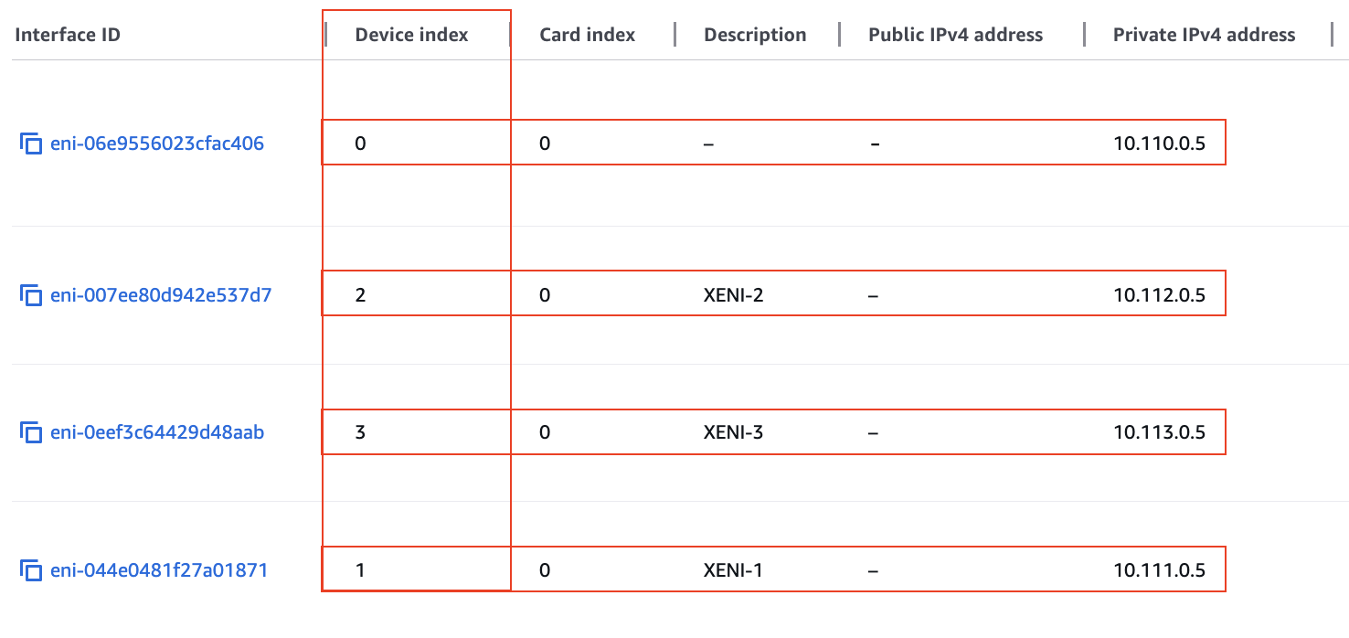
Figure 8 – Device Index on the Elastic Network Interface
Note: Keep track of the attachment order, as it determines the device index (for example, Management = 0, X-ENI-1 = 1, X-ENI-2 = 2 and so on). Interface numbering inside the appliance may differ from the AWS device index but will typically remain sequential (for example, GigabitEthernet1, GigabitEthernet2 and so on).
Step 4 – Create the Connect Attachment and Connect Peer
- In the AWS Cloud WAN Console, create a new attachment.
- Set the Attachment Type to Connect, select the Edge Location where you want to establish the BGP peer, and choose Tunnel-less (no encapsulation) as the Connect Protocol.
- For the Transport Attachment ID, select the Transport attachment that represents the VRF you are extending.
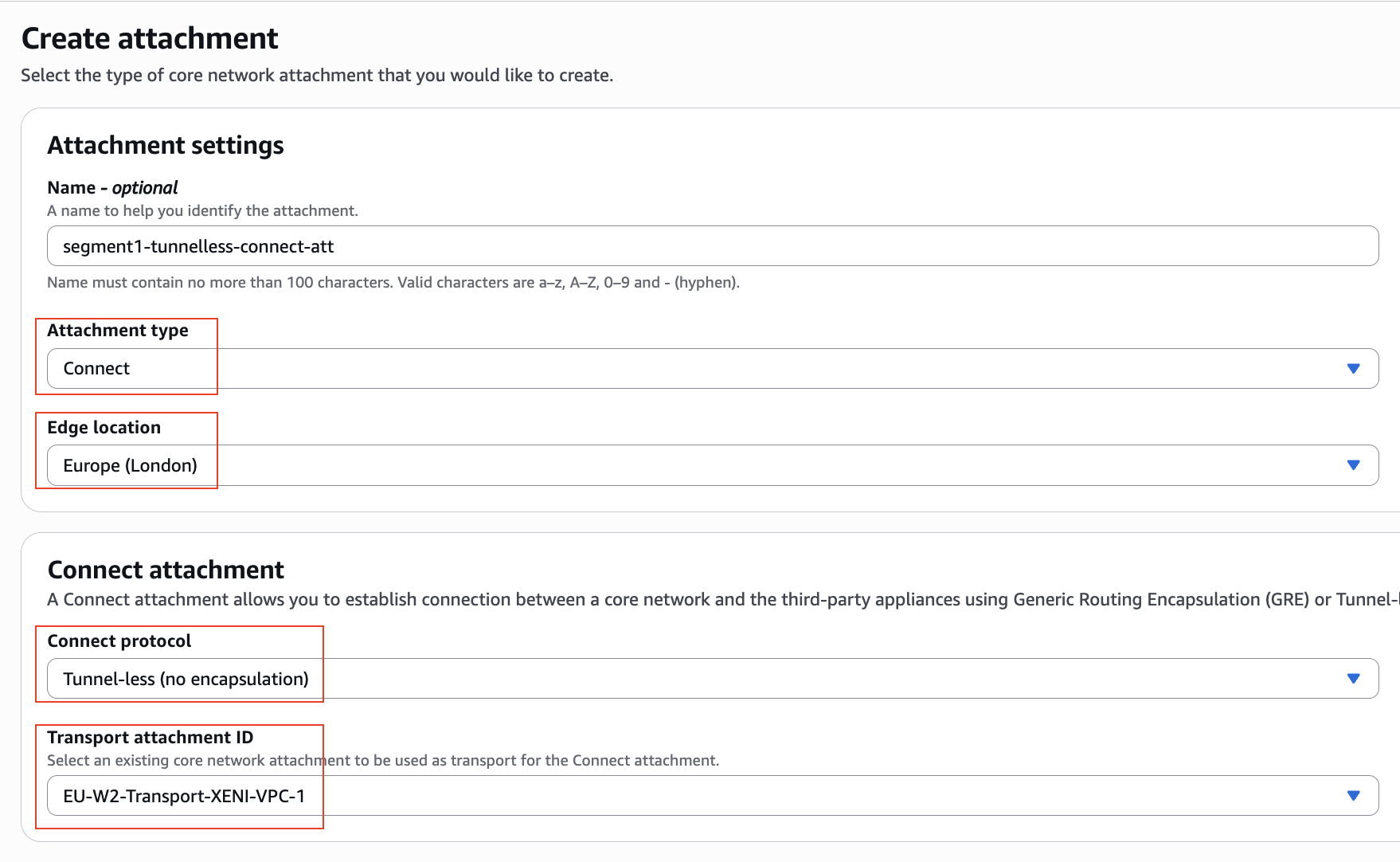
Figure 9 – Connect (Overlay) Attachment for VRF 1
- Apply a tag to enable automatic segment association (the tag-based attachment policy rule must already exist in your AWS Cloud WAN policy). The Transport (Data Plane VPC) attachment and Connect attachment must be associated with the same segment.
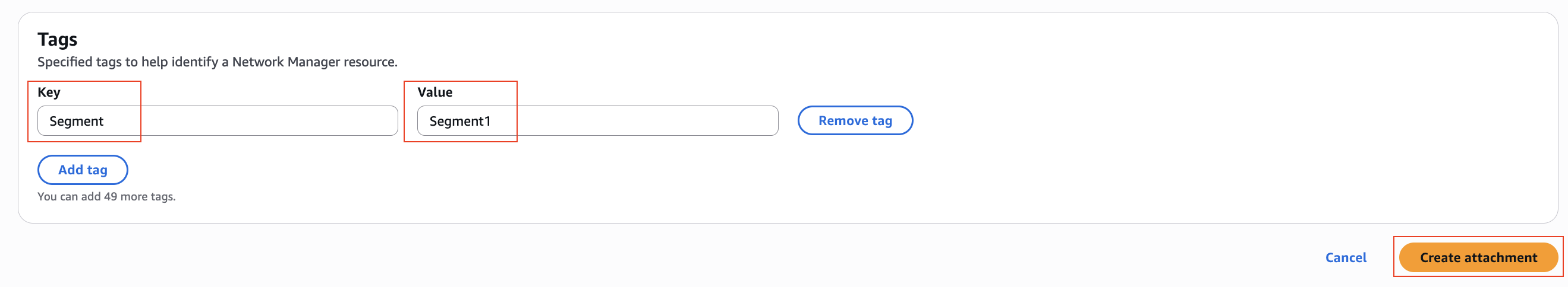 Figure 10 – Name Tag on Connect Attachment
Create the Connect Peer:
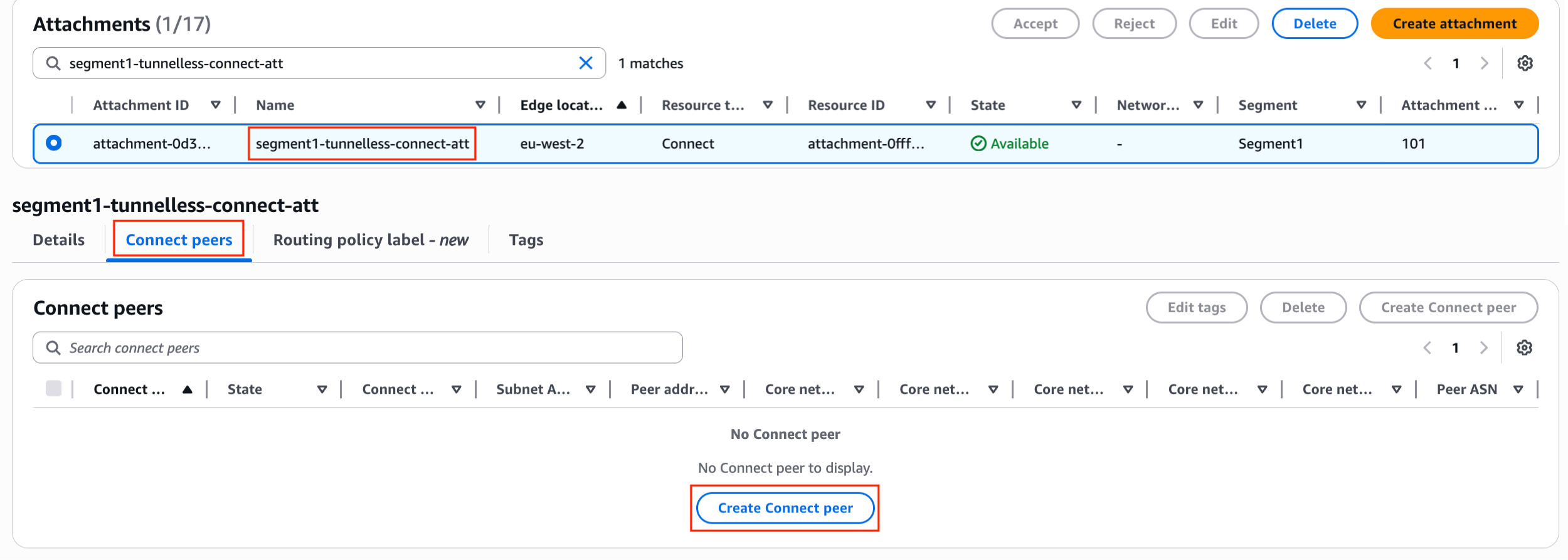
Figure 11 – Navigate to Create Connect peer
When the attachment is created, select it and create the Connect Peer. Specify the Peer BGP IP address (X-ENI IP address), Peer ASN (ASN of the SD-WAN appliance), and the subnet of the X-ENI.
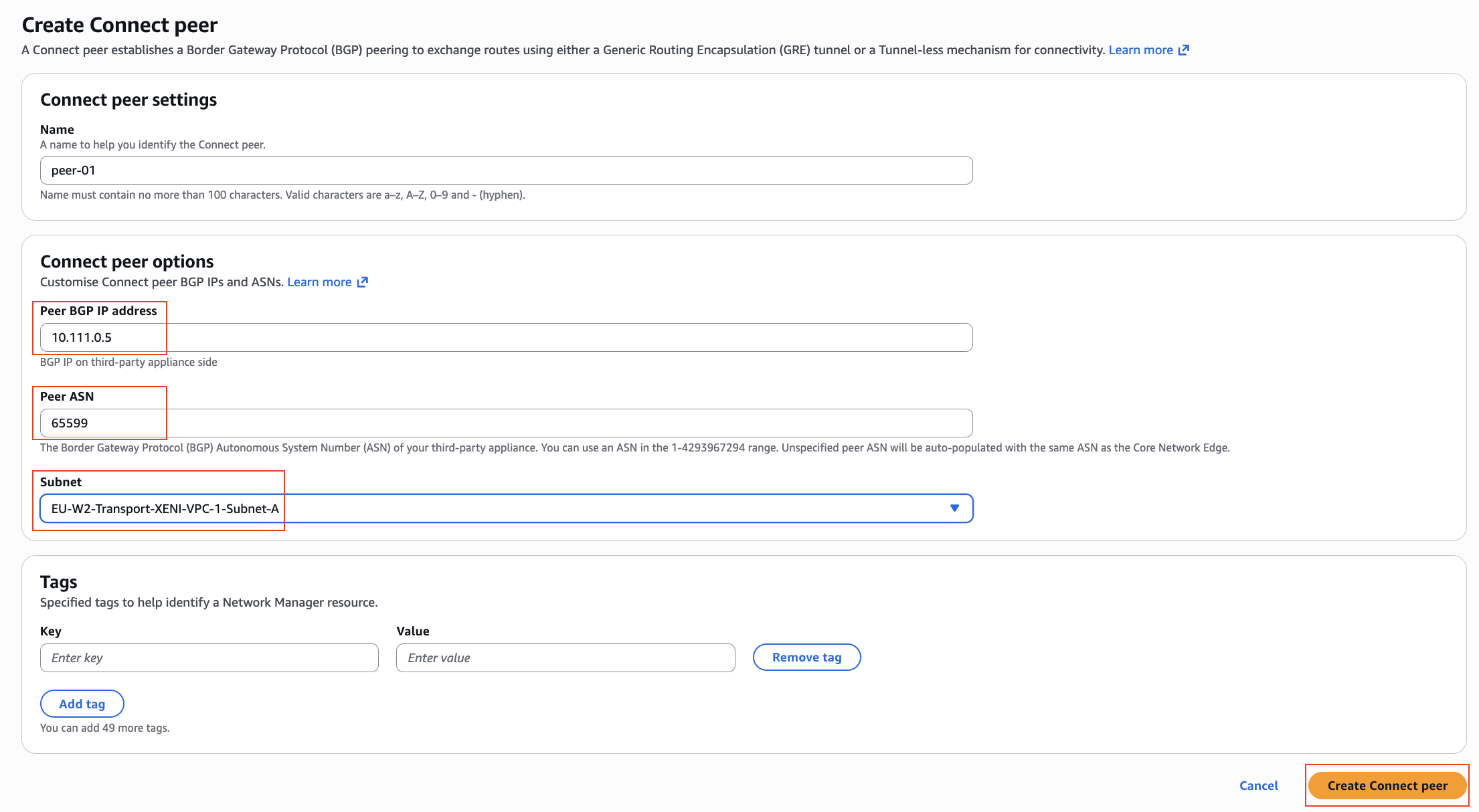
Figure 12 – Configure and Create Connect peer
Note: It may take a few minutes for the peer to be provisioned and for the Core Network Edge BGP Peer IP addresses to be allocated.
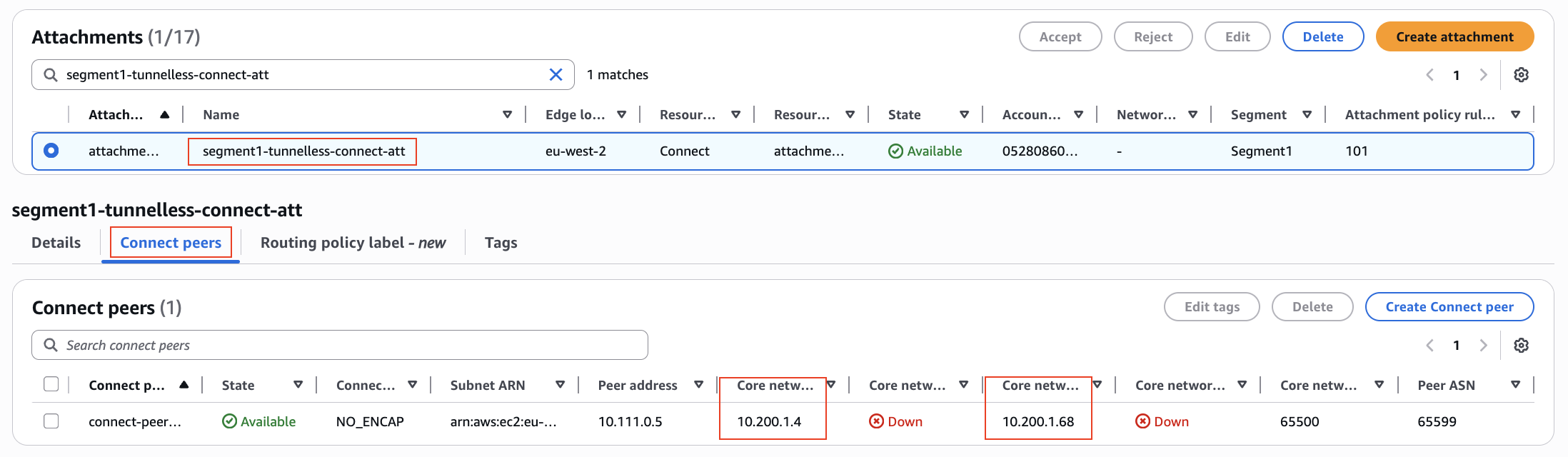
Figure 13 – CNE BGP Peer IPs and Status on Connect peer
Repeat this process for each additional Connect attachment and Connect peer representing other VRFs.
Step 5 – Configure the SD-WAN appliance
Note: The configuration examples below are provided for reference. Adapt the commands to match your SD-WAN vendor’s equivalent syntax as needed.
5.1 – Define the VRFs
If not already configured, create the VRF definitions:
vrf definition vrf1
 rd 101:101
 !
 address-family ipv4
 exit-address-family
!
vrf definition vrf2
 rd 102:102
 !
 address-family ipv4
 exit-address-family
!
vrf definition vrf3
 rd 103:103
 !
 address-family ipv4
 exit-address-family
!
5.2 – Configure the Interfaces
Assign each interface to its respective VRF and configure the IP addressing:
interface GigabitEthernet2
vrf forwarding vrf1
ip address 10.111.0.5 255.255.0.0
no shutdown
!
interface GigabitEthernet3
vrf forwarding vrf2
ip address 10.112.0.5 255.255.0.0
no shutdown
!
interface GigabitEthernet4
vrf forwarding vrf3
ip address 10.113.0.5 255.255.0.0
no shutdown
!
Validate that each interface is up and assigned to the correct VRF:
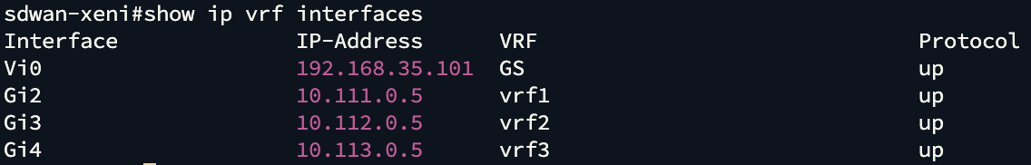 Figure 14 – VRF Interfaces in SD-WAN Appliance
5.3 – Configure Default Routes for Each VRF
ip route vrf vrf1 0.0.0.0 0.0.0.0 10.111.0.1
ip route vrf vrf2 0.0.0.0 0.0.0.0 10.112.0.1
ip route vrf vrf3 0.0.0.0 0.0.0.0 10.113.0.1
Note: The next-hop is the subnet’s “+1” address — an AWS-reserved implicit VPC router. It is not visible in the Amazon EC2 Console but is reachable using ping from the appliance.
Test connectivity from each VRF interface to its respective implicit VPC router:
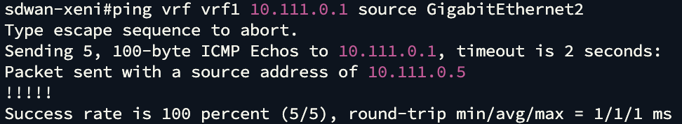 Figure 15 – Ping test from VRF 1 interface to XENI VPC 1 implicit AWS Router
Repeat the test for all VRFs, from their associated interfaces to their respective implicit VPC router IP.
5.4 – Add Host Routes to BGP Peers
! VRF1 peers
ip route vrf vrf1 10.200.1.4  255.255.255.255 10.111.0.1
ip route vrf vrf1 10.200.1.68 255.255.255.255 10.111.0.1
! VRF2 peers
ip route vrf vrf2 10.200.1.16 255.255.255.255 10.112.0.1
ip route vrf vrf2 10.200.1.58 255.255.255.255 10.112.0.1
! VRF3 peers
ip route vrf vrf3 10.200.1.33 255.255.255.255 10.113.0.1
ip route vrf vrf3 10.200.1.84 255.255.255.255 10.113.0.1
The BGP Peer IPs, noted as 10.200.1.x addresses above are the Connect peers which can be found in the Connect Peers tab for each Tunnel-less Connect attachment, as shown in Figure 13 above.
Note: Some vendors may require specific routes for BGP session establishment instead of the default route. Refer to your vendor’s documentation for details. If not required, then you can skip step 5.4.
Test connectivity from the VRF interface to its respective AWS Cloud WAN BGP peer IPs:
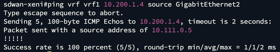 Figure 16 – Ping test from VRF 1 interface to CNE BGP Peer IP 1
Repeat the test for all VRFs, from their associated interfaces to their respective BGP Peer IPs in AWS Cloud WAN.
5.5 – Configure BGP
router bgp 65599
bgp log-neighbor-changes
!
address-family ipv4 vrf vrf1
network 172.16.1.0 mask 255.255.255.0
neighbor 10.200.1.4 remote-as 65500
neighbor 10.200.1.4 ebgp-multihop 2
neighbor 10.200.1.4 update-source GigabitEthernet2
neighbor 10.200.1.4 activate
neighbor 10.200.1.68 remote-as 65500
neighbor 10.200.1.68 ebgp-multihop 2
neighbor 10.200.1.68 update-source GigabitEthernet2
neighbor 10.200.1.68 activate
redistribute connected
exit-address-family
!
address-family ipv4 vrf vrf2
network 172.16.2.0 mask 255.255.255.0
neighbor 10.200.1.16 remote-as 65500
neighbor 10.200.1.16 ebgp-multihop 2
neighbor 10.200.1.16 update-source GigabitEthernet3
neighbor 10.200.1.16 activate
neighbor 10.200.1.58 remote-as 65500
neighbor 10.200.1.58 ebgp-multihop 2
neighbor 10.200.1.58 update-source GigabitEthernet
neighbor 10.200.1.58 activate
redistribute connected
exit-address-family
!
address-family ipv4 vrf vrf3
network 172.16.3.0 mask 255.255.255.0
neighbor 10.200.1.33 remote-as 65500
neighbor 10.200.1.33 ebgp-multihop 2
neighbor 10.200.1.33 update-source GigabitEthernet4
neighbor 10.200.1.33 activate
neighbor 10.200.1.84 remote-as 65500
neighbor 10.200.1.84 ebgp-multihop 2
neighbor 10.200.1.84 update-source GigabitEthernet4
neighbor 10.200.1.84 activate
redistribute connected
exit-address-family
6. Validate the Deployment
6.1 – Validation on the SD-WAN Appliance
BGP Neighbor Status:
Verify that all BGP neighbors are up, and that prefixes are being exchanged.
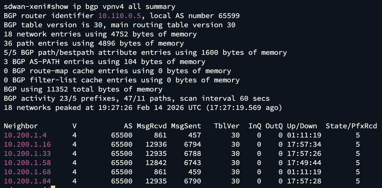 Figure 17 – BGP Status for all neighbors
Verify route tables across all VRFs:
Confirm that routes received from AWS Cloud WAN appear in each VRF’s routing table. Verify that only VPCs associated with the Cloud WAN segment representing a given VRF are propagating their VPC CIDR. For example:
The 10.1.x.0/24 prefixes represent VPCs located in eu-west-2 (London), and the 10.2.x.0/24 prefixes represent VPCs located in us-east-1 (North Virginia).
- VRF1 receives the 10.1.1.0/24 and 10.2.1.0/24 prefixes — both VPCs are associated with Segment1.
- VRF2 receives the 10.1.2.0/24 and 10.2.2.0/24 prefixes — both VPCs are associated with Segment2.
- VRF3 receives the 10.1.3.0/24 and 10.2.3.0/24 prefixes — both VPCs are associated with Segment3.
No routes leak between VRFs, validating end-to-end VRF extension.
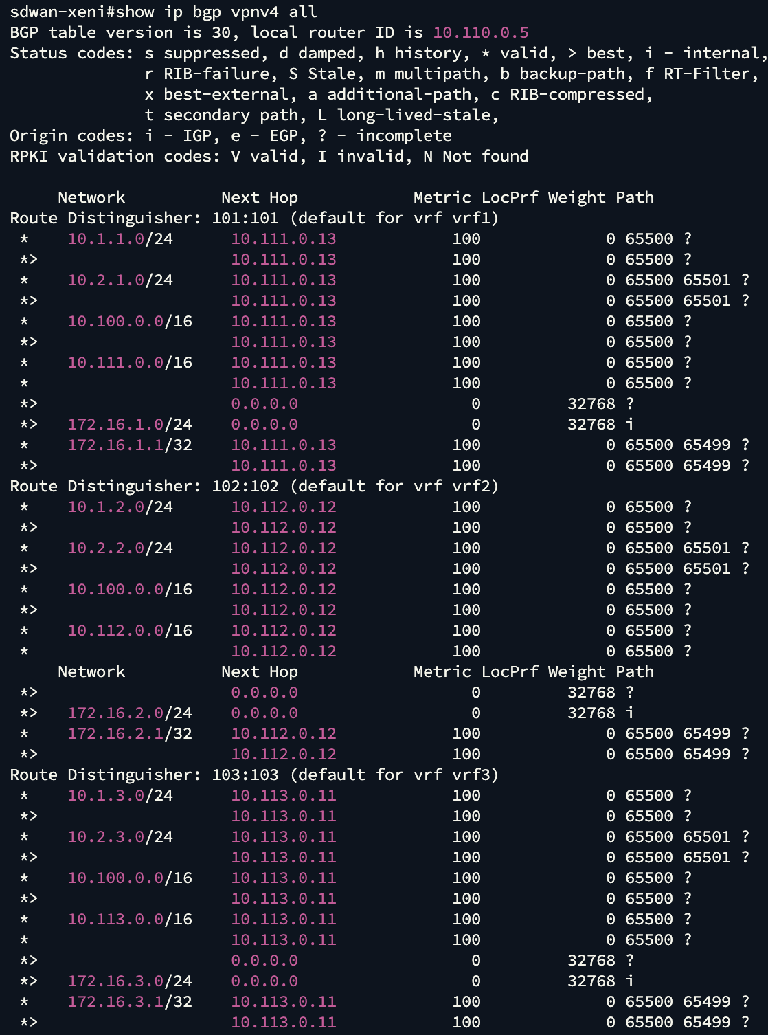 Figure 18 – Learned prefixes across all VRFs
6.2 – Validation on AWS Cloud WAN
BGP Neighbor status:
Navigate to the Connect Peer in the AWS Cloud WAN Console and verify the BGP status is Up.
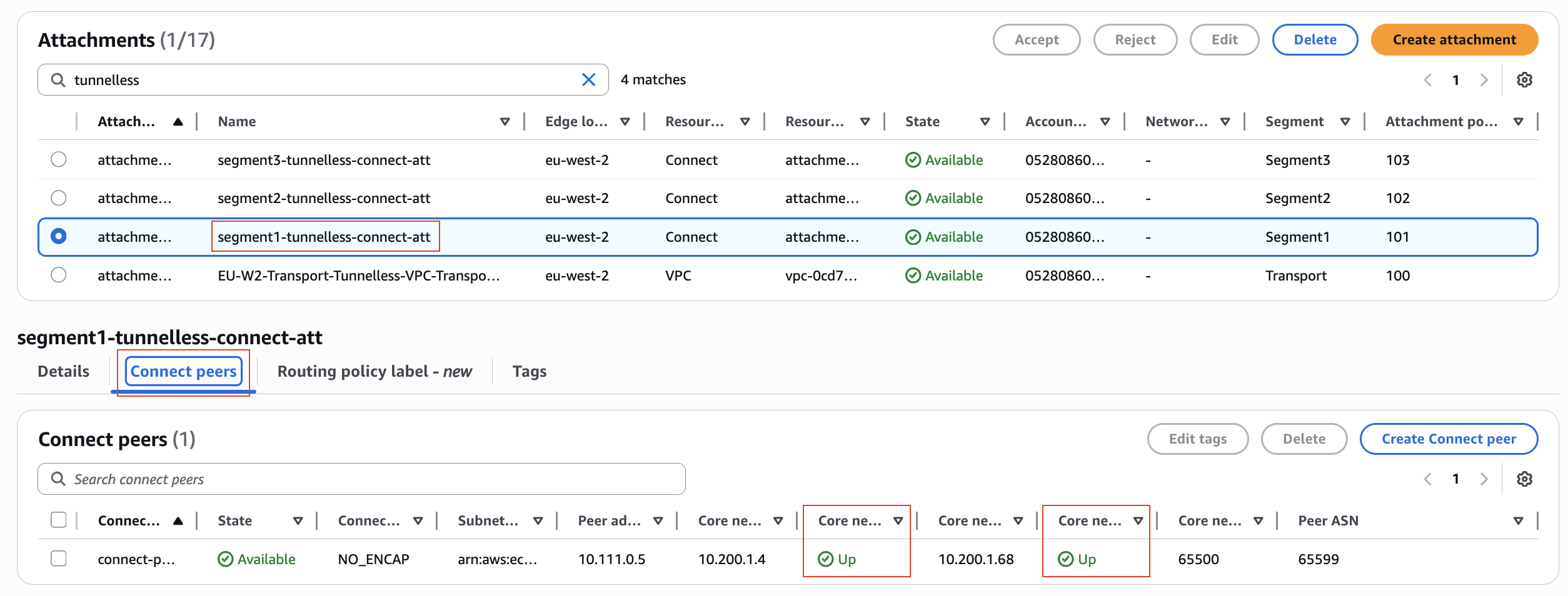 Figure 19 – BGP Status in Connect peers
Note: It may take several minutes for the BGP status to update in the AWS Console.
Routing Information Base (RIB):
Navigate to the Routing Information Base within the AWS Cloud WAN Console, select the Segment representing the VRF you want to validate, and the peered Edge Location.
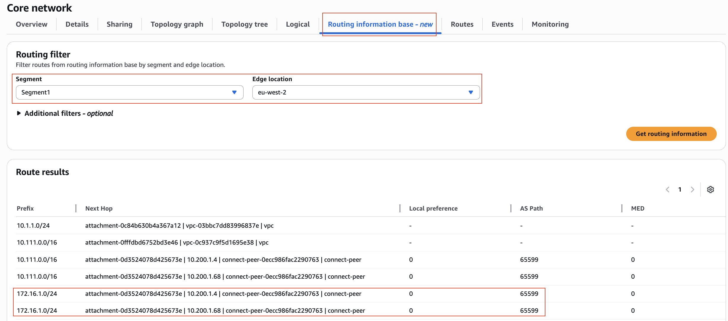 Figure 20 – AWS Cloud WAN Routing Information Base
Note: The RIB shows the routes received. After route evaluation, AWS Cloud WAN selects the best route and installs it into the route table — the Forwarding Information Base (FIB) used for actual packet forwarding. Note that the RIB and route tables are updated immediately after a route change, while the console may take slightly longer to reflect the latest state.
Architectural Comparison and Use Cases
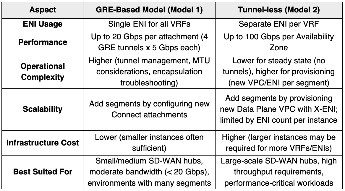
In this section, a comparison between the GRE-based Connect attachment model described in Part 1 with the tunnel-less Connect attachment model, highlighting the key differences and appropriate use cases for each approach.
Performance & Scalability
Tunnel-less Connect supports up to 100 Gbps per Availability Zone — the full bandwidth of a VPC attachment — with no encapsulation overhead. GRE-based Connect is limited to 5 Gbps per tunnel (20 Gbps per attachment using four peers with ECMP) and introduces packet overhead that reduces effective throughput. However, Tunnel-less Connect requires a separate ENI for each VRF/segment, and ENI count per EC2 instance is limited by instance type.
Operational Complexity
GRE-based Connect requires more operational effort: tunnel creation, BGP configuration across multiple peers or attachments, and ongoing tunnel maintenance. Tunnel-less Connect removes this overhead entirely.
However, there is a provisioning trade-off. Adding a VRF in the GRE-based Connect requires only a new Connect attachment on an existing transport. In the Tunnel-less Connect, it requires a new Data Plane VPC, X-ENIs, and both VPC and Connect attachments — overhead that should be factored into operational runbooks and automation.
Cost Considerations
Each VRF requires a dedicated ENI, and both ENI count and network performance are tied to instance type. More VRFs may require larger, more expensive instances.
To maximize efficiency:
- Right-size instances to your VRF count and bandwidth requirements.
- Consolidate VRFs where segmentation policy permits.
- Use AWS Savings Plans or Reserved Instances for steady-state workloads.
Careful planning around ENI quotas and instance sizing is essential to balancing performance, segmentation requirements, and cost.
Conclusion
AWS Cloud WAN provides flexible options for extending SD-WAN connectivity into AWS while maintaining strict network segmentation. As organizations grow and their network requirements evolve, choosing the right architectural model becomes critical for balancing performance, scalability, operational complexity, and cost. By understanding the trade-offs of each approach — detailed in the comparison above — enterprises can design architectures that align with their network segmentation, compliance, and bandwidth needs.
Whether you are modernizing an existing SD-WAN deployment or building a new cloud network, the architectural flexibility of AWS Cloud WAN helps you meet your connectivity and security goals at scale.