Networking & Content Delivery
Extending SD-WAN Segmentation into AWS Cloud WAN – Part 1
For organizations operating multi-tenant environments, regulated environments, or multiple business units, maintaining strict network segmentation between SD-WAN and AWS is essential for meeting security, compliance, and operational requirements. Deploying SD-WAN virtual appliances and extending your segmentation through AWS Cloud WAN helps unify these segmented environments under a single, scalable global network.
That said, segmentation is not a requirement for every customer. A perfectly valid approach using a single SD-WAN segment as described in Build Global SD-WANs with AWS Cloud WAN Tunnel-less Connect, where you can enforce segmentation through security policies, firewall rules, and access controls rather than strict network separation may meet your requirements.
For customers who do require segmentation to support compliance, isolate workloads, or manage overlapping IP addresses, extending those segment boundaries into the cloud is essential. Traditionally, organizations achieved this by connecting SD-WAN appliances located on-premises or in colocation facilities to AWS over Direct Connect, using multiple virtual interfaces or AWS Transit Gateway Connect attachments to maintain a clear separation between network segments. These approaches remain effective and widely used today.
However, deploying SD-WAN virtual appliances directly within the cloud reduces the need for physical infrastructure, enables faster scaling, and allows remote sites to access AWS resources directly without backhauling traffic through centralized data centers.
This is Part 1 of a two-part series on extending segmentation using SD-WAN virtual appliances with AWS Cloud WAN. In this post, we explore Model 1: Multiple Generic Routing Encapsulation (GRE) based Connect attachments over a single network interface, demonstrating how to preserve end-to-end segmentation with a minimal deployment footprint. Part 2 covers the Tunnel-less Connect approach with Multi-VPC ENIs for organizations seeking higher bandwidth, without the need for encapsulation or tunneling overhead.
Connecting SD-WAN to AWS
Customers typically connect their SD-WAN environments to AWS using one of two main approaches, as shown below in Figure 1.
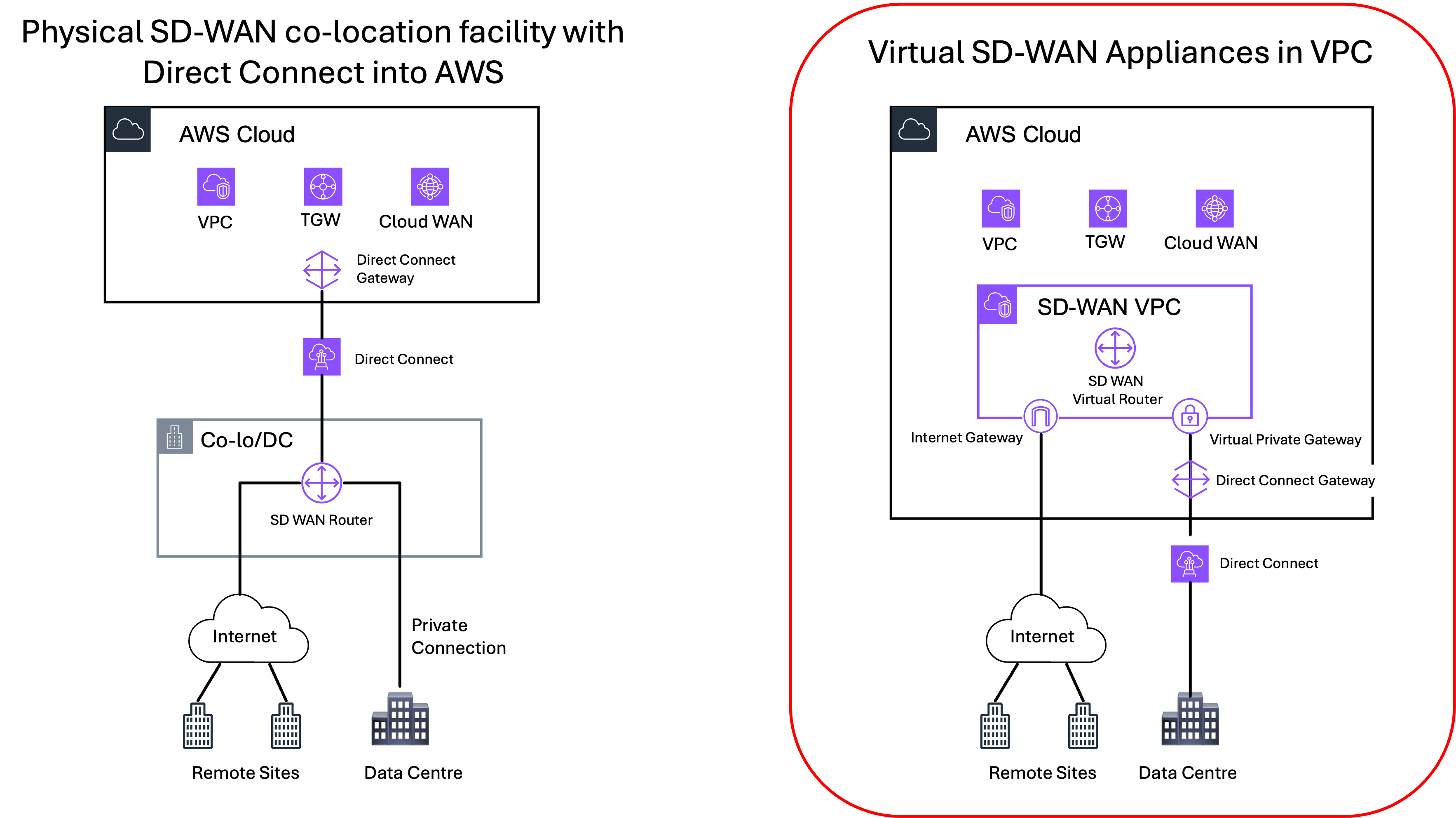
Figure 1: Connecting SD-WAN to AWS – physical vs virtual appliances
- Physical appliances at on-premises or colocation facilities: Deploy SD-WAN physical appliances in on-premises data centers or colocation facilities and connect them to AWS using AWS Direct Connect. This approach is well-established and continues to be a proven and reliable option, especially for customers with existing infrastructure and dedicated network backbones.
- Virtual appliances deployed in AWS: Deploy SD-WAN virtual appliances directly into AWS and connect to them over the internet or Direct Connect, as needed. This cloud-centered approach aligns well with organizations moving toward flexible, scalable, and asset-light network models.
This post series covers the second approach: deploying SD-WAN virtual appliances in AWS and extending network segmentation through AWS Cloud WAN. By deploying virtual SD-WAN appliances directly in AWS, you can:
- Minimize reliance on physical hardware and facilities by shifting network functions into the cloud.
- Move away from traditional connectivity models like MPLS and avoid long-term commitment. You pay only for what you use with AWS pay-as-you-go pricing.
- Use Infrastructure as Code (IaC) to rapidly deploy, modify, or decommission connectivity.
- Scale to new regions in minutes and adjust your network dynamically as business needs evolve.
- Enable decentralized, direct access from remote sites to cloud workloads bypassing central hubs and reducing latency.
- Take advantage of AWS global footprint and support for multiple connection types to quickly expand your network across regions.
- Adopt a cloud-first strategy by extending your SD-WAN directly into AWS, aligning network architecture with modern application deployment models.
Solution Overview
Extending network segmentation from SD-WAN virtual appliances into AWS Cloud WAN involves aligning the segmentation domains defined in the SD-WAN — typically represented as separate Virtual Routing and Forwarding (VRF) instances — with the corresponding AWS Cloud WAN segment. This mapping helps ensure that traffic isolation, policy enforcement, and routing boundaries established on the SD-WAN side are consistently extended into the AWS cloud environment, maintaining end-to-end segmentation across the hybrid network.
Figure 2 illustrates this mapping, showing how SD-WAN segmentation domains map to AWS Cloud WAN segments to maintain end-to-end isolation.
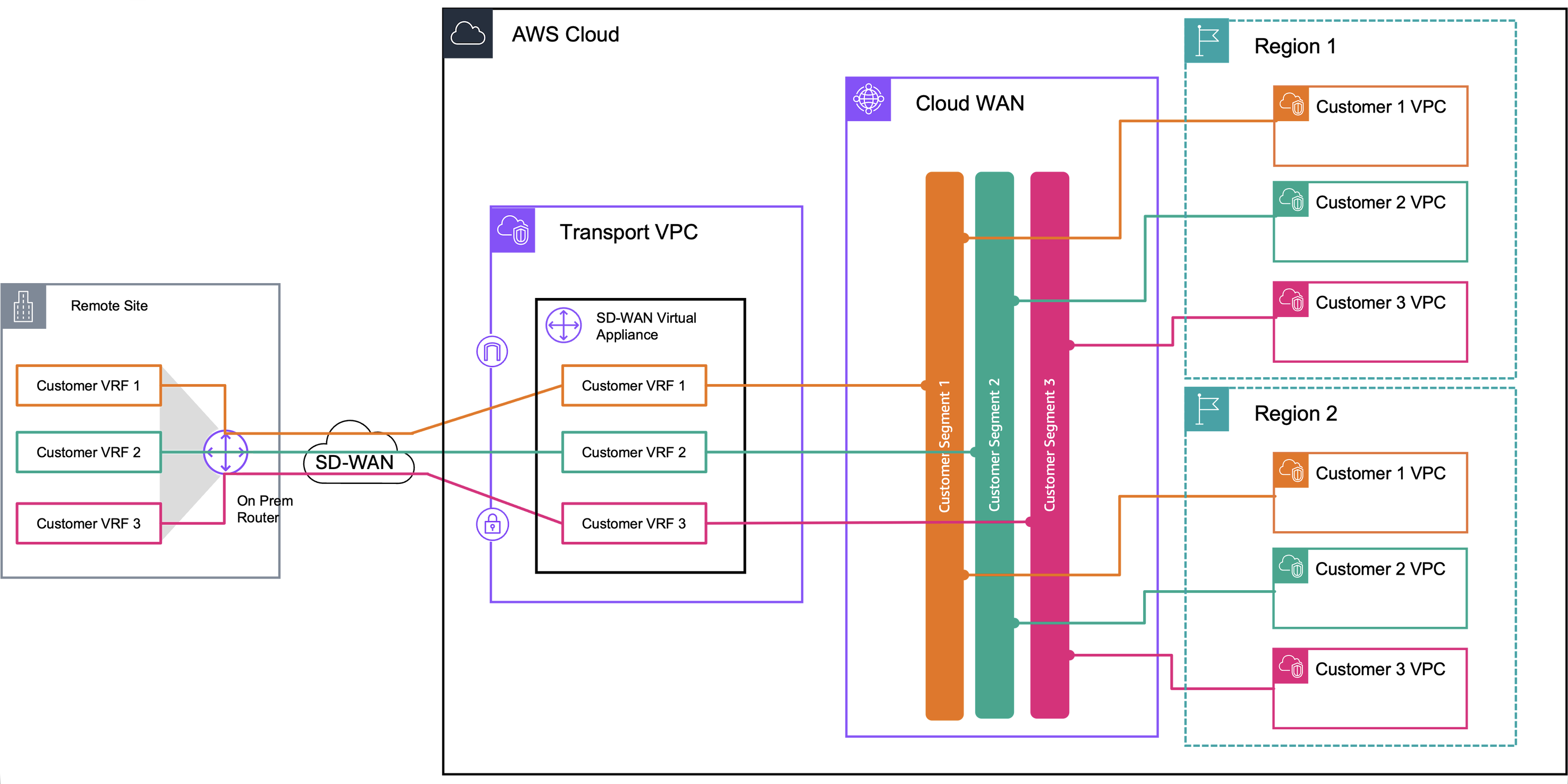
Figure 2: Target solution – end-to-end segmentation
AWS Cloud WAN offers two primary architectural models for integrating SD-WAN virtual appliances while preserving network segmentation:
- Multiple GRE-based Connect attachments over a single interface: In this model, multiple AWS Cloud WAN GRE-based Connect attachments are created, each mapping to a separate SD-WAN VRF. These connect to a single Elastic Network Interface (ENI) on the SD-WAN virtual appliance. Each Connect attachment uses Generic Routing Encapsulation (GRE) tunnels to carry traffic between the SD-WAN VRF and its corresponding AWS Cloud WAN segment. This approach enables the support of multiple VRFs over a single transport attachment.
- Tunnel-less Connect with Multi-VPC ENI (X-ENI): With the introduction of Tunnel-less Connect, SD-WAN appliances can establish direct BGP peering with AWS Cloud WAN, removing the need for GRE tunneling and encapsulation. This reduces complexity and improves performance by removing tunneling overhead. However, as Tunnel-less Connect requires both the Transport attachment and the Connect attachment to be associated with the same AWS Cloud WAN segment, customers can use Multi-VPC ENI attachments (also known as X-ENI) to associate different interfaces on the SD-WAN appliance with different segments. Each interface effectively maps to a unique VRF, allowing segmentation to be preserved without tunneling.
This is Part 1 of a two-part series on extending segmentation using SD-WAN virtual appliances with AWS Cloud WAN. Here, we demonstrate how to deploy Multiple GRE-based Connect attachments over a single interface (Model 1). If you’re looking for Model 2 — Tunnel-less Connect with Multi-VPC ENI (X-ENI) — head to Part 2 of this series.
Model 1: Multiple GRE-based Connect attachments over a single interface
Architecture Overview
This deployment model uses AWS Cloud WAN GRE-based Connect attachments to easily integrate SD-WAN virtual appliances into the AWS Cloud WAN core network, while maintaining strict network segmentation across environments.
We deploy the SD-WAN appliances in a dedicated Amazon VPC with a single data interface. Each VRF on the appliance maps to a corresponding AWS Cloud WAN segment through a separate GRE-based Connect attachment, using the VPC attachment as its Transport. Because Connect and Transport attachments can be mapped to different segments independently, this model enables granular traffic segmentation and policy enforcement across VRFs.
Each GRE tunnel, configured through a Connect peer, supports up to 5 Gbps of bandwidth. With support for up to four peers per Connect attachment, the architecture can scale up to 20 Gbps per attachment (per VRF/Segment), meeting high throughput demands while preserving segmentation and routing control.
By mapping each GRE-based Connect attachment to a specific AWS Cloud WAN segment, this model enables segmented, secure connectivity between on-premises SD-WAN deployments and AWS-hosted workloads. It is especially well-suited for enterprises requiring strict separation of traffic between environments such as production, development, and testing, or across different business units as well as for multi-tenant environments.
Architecture Diagram
Figure 3 illustrates how a single interface SD-WAN virtual appliance extends network segmentation to AWS Cloud WAN using GRE-based Connect attachments, mapping multiple VRFs to distinct AWS Cloud WAN segments. The diagram is conceptual and shows a single Availability Zone for simplicity; however, we recommend a multi-AZ deployment. For large-scale global networks, we recommend using multiple AWS Regions for efficient routing.
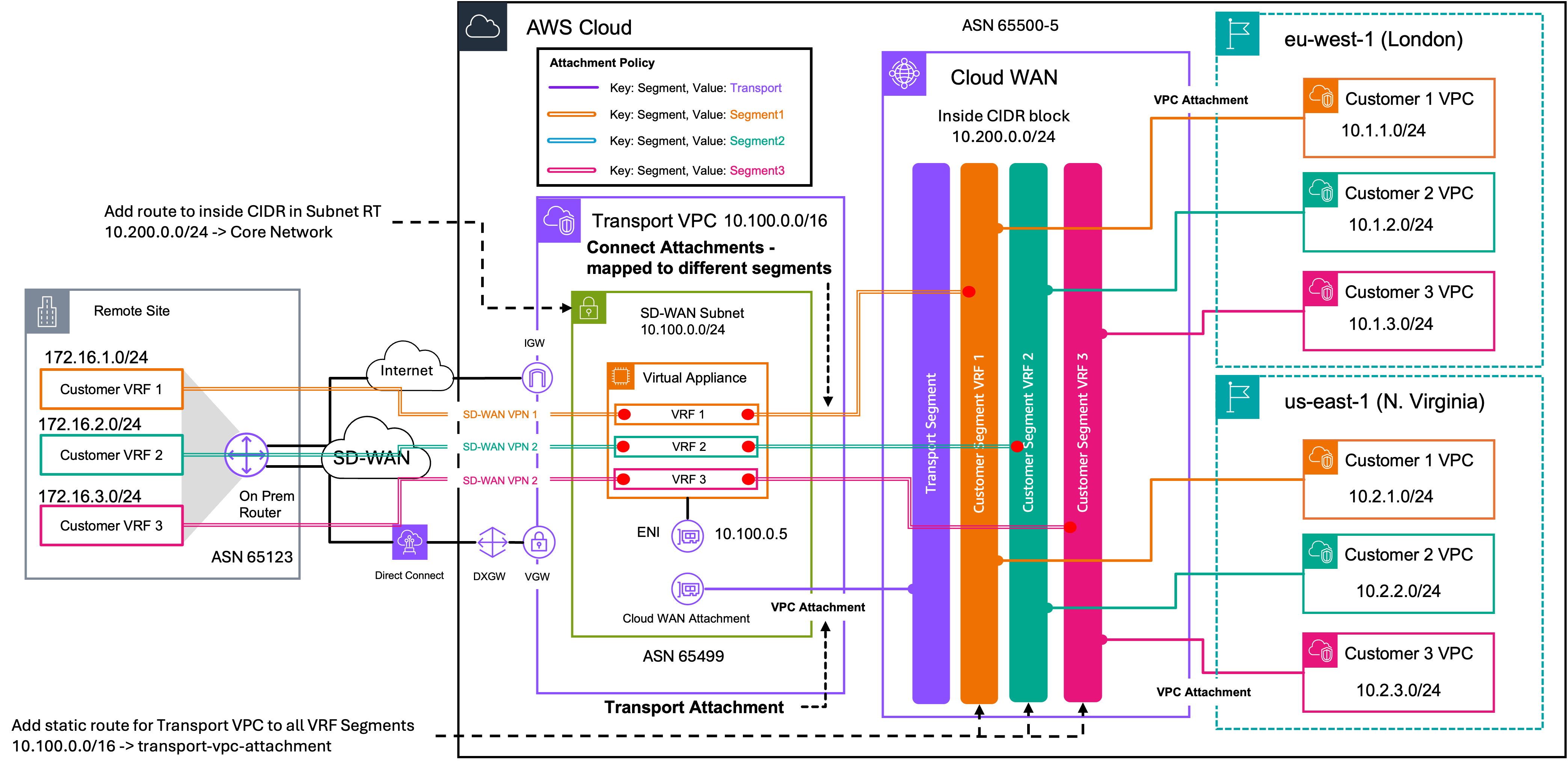
Figure 3: Model 1 – Extending network segmentation with single interface SD-WAN virtual appliance using GRE-based Connect
Prerequisites
In this section, we focus on the connectivity between the SD-WAN appliance and AWS Cloud WAN. We do not cover the deployment of the AWS Cloud WAN core network or the SD-WAN appliance itself. As prerequisites, we assume the following:
- The AWS Cloud WAN core network is deployed with the necessary segments
- The SD-WAN appliance is deployed in a Transport VPC, according to vendor recommendations
- Source/destination checks are enabled by default. You must disable source/destination checks on all data plane interfaces of the appliance.
- Familiarity with GRE tunnel configuration on your SD-WAN platform
- An understanding of Virtual Routing & Forwarding instances (VRFs) and network segmentation concepts
Deployment Steps
Step 1 – Allocate an inside CIDR block to the AWS Cloud WAN Core Network
An Inside CIDR block is required for attaching Connect attachments to a Core Network Edge. This CIDR block provides the outer IP addresses for the BGP Peer IPs on the AWS Cloud WAN side.
- Navigate to the VPC console in your AWS Account and select Cloud WAN. This will take you to AWS Network Manager
- Select Global Networks and select your global network.
- Under Core network, select Policy versions and Edit the live policy version.
- Under the Network configuration tab, scroll down to Inside CIDR blocks and select Create.
- Enter the CIDR block to be used for the BGP Peer IPs on Connect peers and select Create inside CIDR block. This is the supernet/summary CIDR range. Each edge location (Core Network Edge) where an SD-WAN appliance will be peered to, will require a specific Inside CIDR block, allocated from this summary inside CIDR block.
- In the Edge locations section, select each CNE, choose Edit, enter the Inside CIDR block and select Edit edge location. Assign a different Inside CIDR per Edge location. This CIDR must be allocated from the Inside CIDR block defined in Step 5 above.
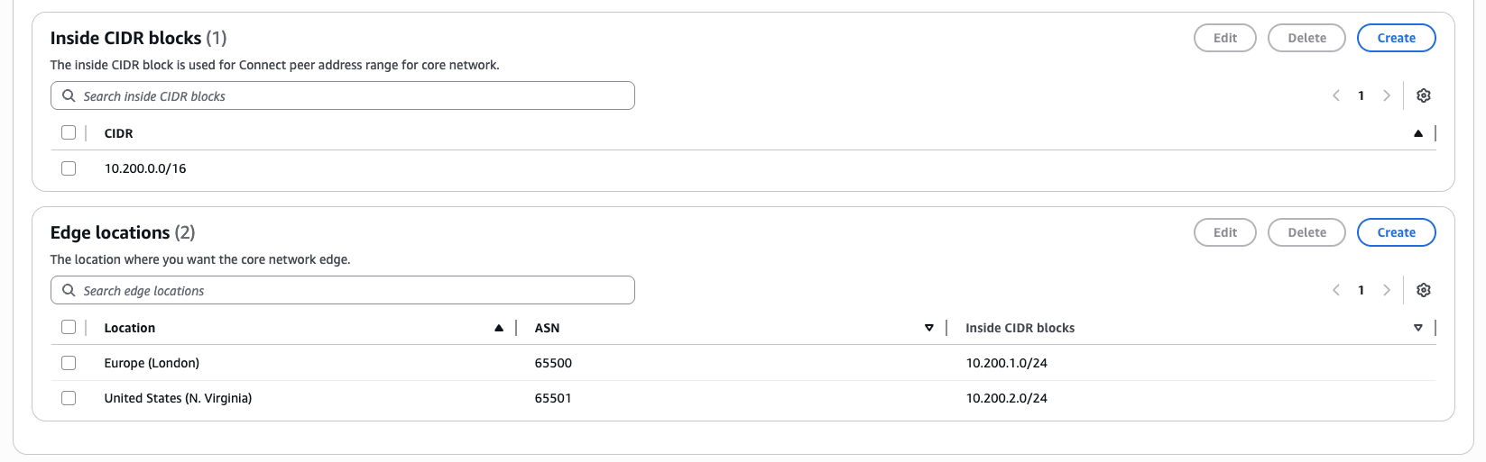
Figure 4: Assign Inside CIDRs to AWS Cloud WAN Edge locations for Connect attachments.
Step 2 – Create attachment policies for Transport VPC and Connect attachments
A Transport segment is required to attach the Transport VPC, where the SD-WAN appliances are deployed, to AWS Cloud WAN. This enables two key functions: configuring the Connect attachments over the VPC attachment and allowing AWS Cloud WAN to learn the routes to the Transport VPC to reach the SD-WAN appliances. The Transport attachment acts as the underlay network, while the Connect attachment functions as the overlay network.
The attachment policy determines which segment an attachment is mapped to. With the policy below, when we create the Transport VPC attachment in Step 3 with the tag key Segment and tag value Transport, AWS Cloud WAN automatically maps it to the Transport segment.
Attachment policy for Transport VPC attachment:
- Continue editing the policy, select the Attachment policies tab and choose Create
- For Rule number enter 100 (or an appropriate value if you have existing rules with the same rule number)
- For Attach to segment, select the Transport segment
- Under Conditions, select Add and use the following values:
- Type: Tag value
- Operator: Equals
- Condition values: Tag key: Segment and Tag value: Transport
- Select Create attachment policy
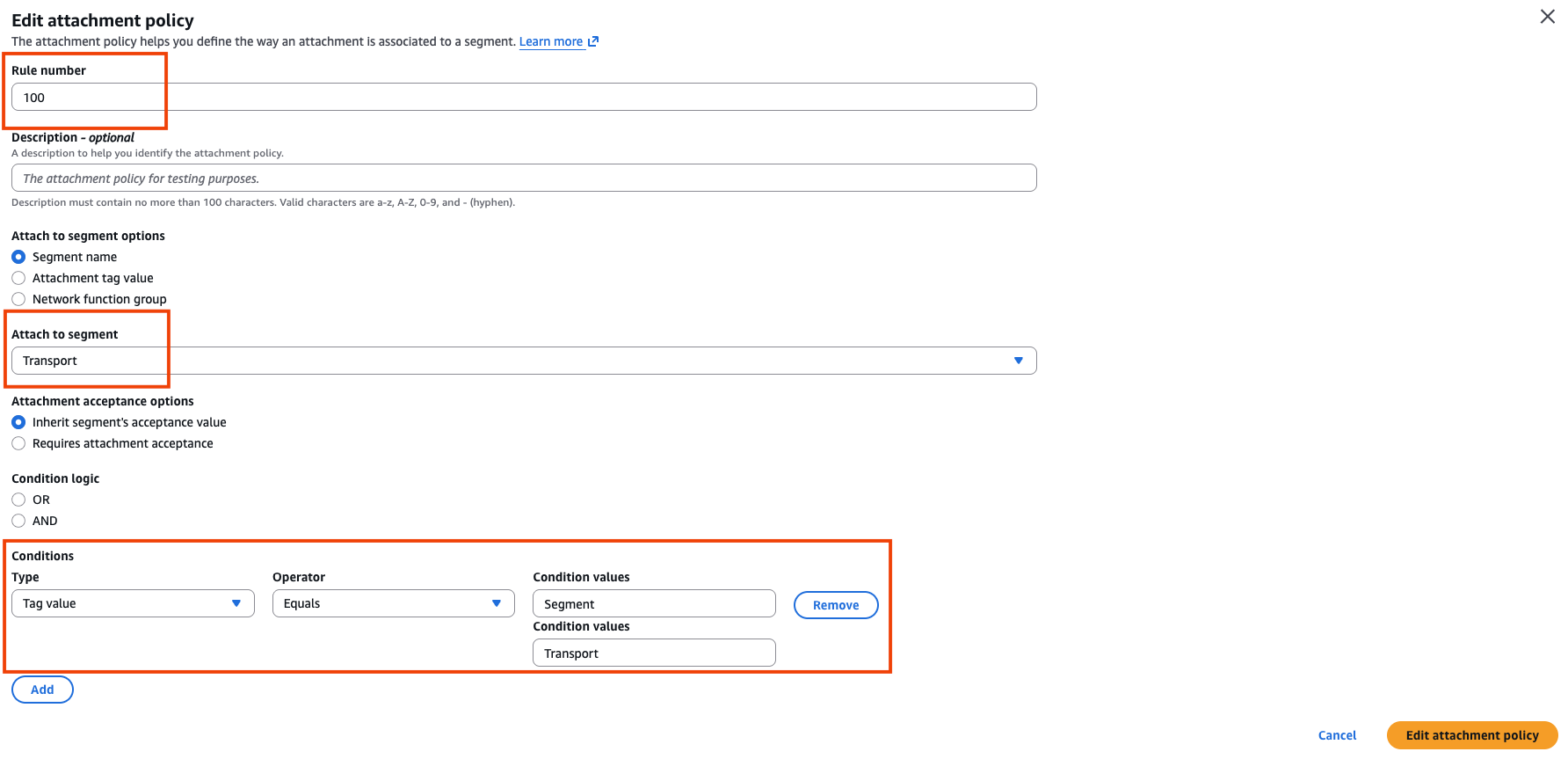
Figure 5: Transport VPC attachment policy
Attachment policy for Connect attachments:
- Continue editing the policy, select the Attachment policies tab and choose Create
- For Rule number enter 101 (or an appropriate value if you have existing rules with the same rule number)
- For Attach to segment, select Segment1
- Under Conditions, select Add and use the following values:
- Type: Tag value
- Operator: Equals
- Condition values: Tag key: Segment and Tag value: Segment1
- Select Create attachment policy
- Repeat steps 1 to 5 for subsequent segments (Segment2 and Segment3 in the present example) using a different rule number and the corresponding tag value.
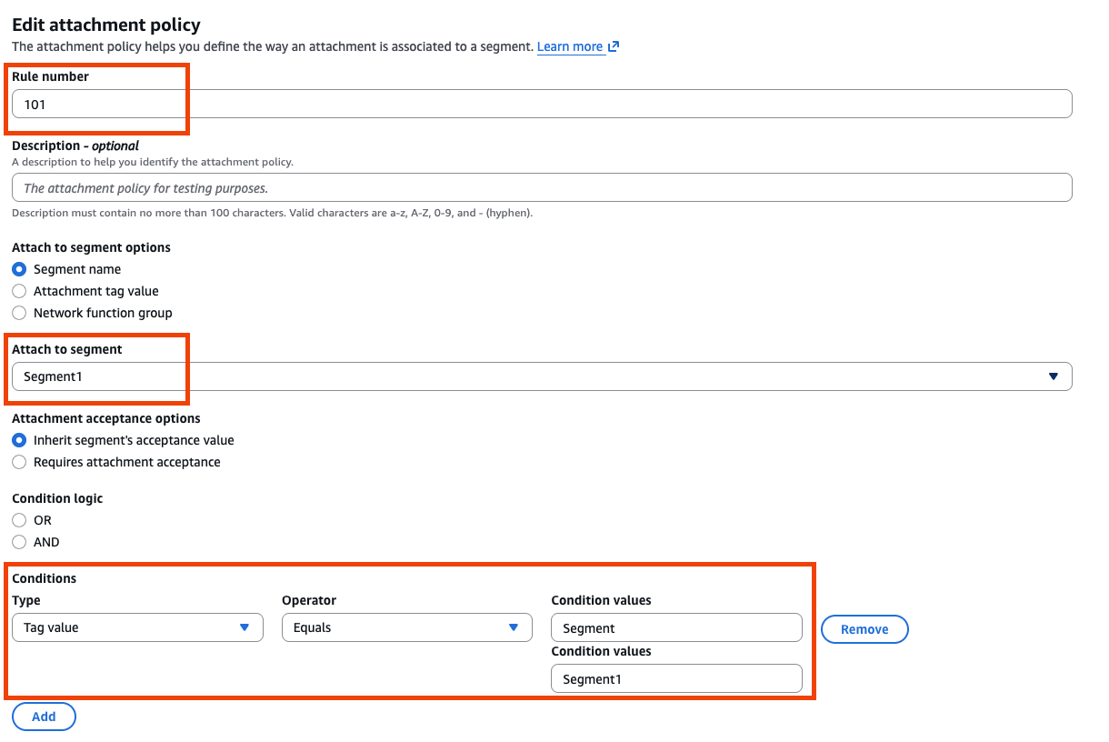
Figure 6: Segment 1 attachment policy
The final attachment policies should appear as shown below in the Figure 7.

Figure 7: Final attachment policies
Once complete, select Create policy, review changes and apply the new policy version by selecting Apply change set.
Step 3 – Create a VPC attachment for the Transport VPC where the SD-WAN virtual appliance resides.
It is recommended to place the AWS Cloud WAN VPC attachment in the same subnet as the virtual appliance; this will allow you to deploy a Tunnel-less Connect attachment with seamless integration, if required in the future.
- Under Core network navigate to Attachments and select Create attachment
- Give your attachment a name e.g. EU-W2-Transport-VPC-Transport-Attachment
- For Attachment type select VPC from the dropdown menu
- Select the Edge Location where your Transport VPC and SD-WAN appliances reside
- For VPC ID select your Transport VPC and the Subnet IDs for your appliances
- For Tags, enter Key: Segment and Value: Transport, make sure to use the same key-value pair defined in your Attachment policy for the Transport Segment. This determines the segment the attachment is associated with, given the attachment policies created.
- Leave the other values as default and select Create attachment
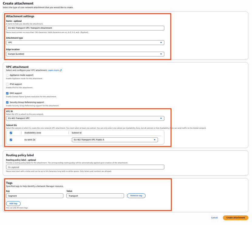
Figure 8: Create Transport VPC attachment
Step 4 – Create Connect attachment and Connect peer to the SD-WAN virtual appliance.
Now create a Connect attachment and a Connect peer for each segment that needs to be mapped to a VRF on the SD-WAN appliance.
Connect attachment
- Under Core network navigate to Attachments and select Create attachment
- Give your attachment a name e.g. segment1-connect-att
- For Attachment type select Connect from the dropdown menu
- Select the Edge Location where your Transport VPC and SD-WAN appliances reside
- For Connect protocol select GRE and for Transport Attachment ID select the EU-W2-Transport-VPC-Transport-Attachment created in the previous step.
- For Tags, enter Key: Segment and Value: Segment1, make sure to use the same key:value pair defined in your Attachment policy for Segment1. This determines the segment the attachment is associated with, given the attachment policies created.
- Leave the other values as default and select Create attachment
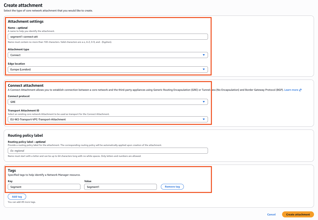
Figure 9: Create GRE-based Connect attachment
Connect Peer
The connect peer creates the GRE tunnel and BGP session between your AWS Cloud WAN Segment and the SD-WAN appliance. You can create up to 4 connect peers for each connect attachment, each providing up to 5 Gbps of bandwidth with a total of up to 20 Gbps per connect attachment.
- Select the Connect attachment created for Segment1
- Select the Connect peers tab and choose Create Connect peer
- Give your Connect peer a Name e.g. vrf1-connect-peer-1
- For Peer GRE address, enter the private IP address of the SD-WAN appliance (e.g. 10.100.0.5)
- For BGP Inside CIDR blocks IPv4 enter a /29 CIDR in the 169.254.0.0/16 range. The CIDR block must not fall within any of the AWS reserved link-local IP ranges.
- For Peer ASN, enter the BGP Autonomous System Number (ASN) of your SD-WAN appliance (e.g. 65499).
- Leave other values as default and select Create Connect peer
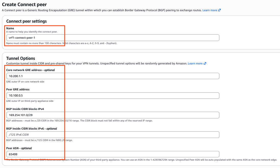
Figure 10: Create the Connect Peer
Step 5 – Create route from the Segments to the Transport VPC
This step enables traffic from AWS Cloud WAN segments 1, 2, and 3 to reach the SD-WAN appliance. By default, these segments do not have a route to the Transport VPC, which is attached to the Transport segment. As an attachment can only be associated with one AWS Cloud WAN Segment, you must explicitly add a route for each segment to route traffic to the Transport VPC attachment to enable end-to-end connectivity. This static route is only required for the underlay/transport CIDR and not the overlay prefix(s), as the overlay prefixes will be propagated via the GRE-based Connect attachment and will have a 1:1 mapping with the segment.
- Under Core network, select Policy versions and Edit your live policy version.
- Under the Segment actions tab, scroll down to Routes and choose Create.
- For Segment from select Segment1
- For Destination CIDR block enter the CIDR range for the Transport VPC (10.100.0.0/16 in this example)
- For Attachments select EU-W2-Transport-VPC-Transport-Attachment from the dropdown menu
- Select Create segment route
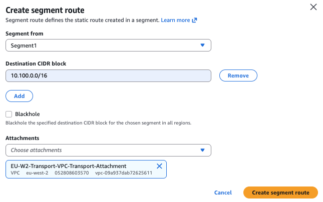
Figure 11: Create static route to Transport VPC
Repeat steps (4) and (5) to create Connect attachments, Connect peers, and the necessary static routes for Segment2 and Segment3. Once done, select Create policy, review changes and apply the new policy version by selecting Apply change set.
Step 6 – Configure your SD-WAN appliance
Use the following steps to configure your appliance. Note that specific configuration steps will vary depending on your SD-WAN vendor; refer to your vendor’s documentation for details.
- Create your VRF if not already created
vrf definition vrf1
rd 101:101
!
address-family ipv4
exit-address-family
- Configure the GRE tunnel and place the tunnel interface in the corresponding VRF, you can find the necessary values to use under your Connect peers
- For tunnel IP address use the IP address under Peer BGP address (e.g. 169.254.101.1)
- For tunnel source, use the appliance interface or Peer address (e.g. 10.100.0.5)
- For tunnel destination, use Core network GRE address (e.g. 10.200.1.1 from the inside CIDR)
interface Tunnel1
vrf forwarding vrf1
ip address 169.254.101.1 255.255.255.248
ip mtu 8500
tunnel source 10.100.0.5
tunnel destination 10.200.1.1
- Configure Multiprotocol BGP (MP-BGP) to advertise VRF-specific routes over each GRE tunnel. This enables dynamic routing between the SD-WAN appliance and AWS Cloud WAN, while maintaining separation across VRFs.
- Use eBGP with ebgp-multihop 2 to establish BGP sessions across GRE tunnels.
- Set the BGP update source to the appropriate GRE tunnel interface using the update-source Tunnel1 (or corresponding tunnel) command to allow BGP session establishment
- Note that when you create a connect peer, you get two BGP peer addresses on AWS Cloud WAN for redundancy (in this example 169.254.101.2 and 169.254.101.3).
router bgp 65499
 bgp log-neighbor-changes
 !
 address-family ipv4
 exit-address-family
 !
 address-family ipv4 vrf vrf1
  neighbor 169.254.101.2 remote-as 65500
  neighbor 169.254.101.2 ebgp-multihop 2
  neighbor 169.254.101.2 update-source Tunnel1
  neighbor 169.254.101.2 activate
  neighbor 169.254.101.3 remote-as 65500
  neighbor 169.254.101.3 ebgp-multihop 2
  neighbor 169.254.101.3 update-source Tunnel1
  neighbor 169.254.101.3 activate
exit-address-family
- Configure a default route for each VRF so that outbound traffic has its next hop as the VPC Implicit Router. This is the +1’ reserved AWS IP address in the subnet.
ip route vrf vrf1 0.0.0.0 0.0.0.0 10.100.0.1
Refer to your vendor’s documentation for specific syntax and best practices related to VRF, GRE and BGP configuration.
Step 7 – Verification
Once you have configured your virtual appliance, return to the AWS Console to verify that the BGP session has been successfully established.
- Navigate to AWS Network Manager
- Under Core network select Attachments
- Choose your Connect attachment and select the Connect peers tab
- Verify that the Core network BGP Status is Up
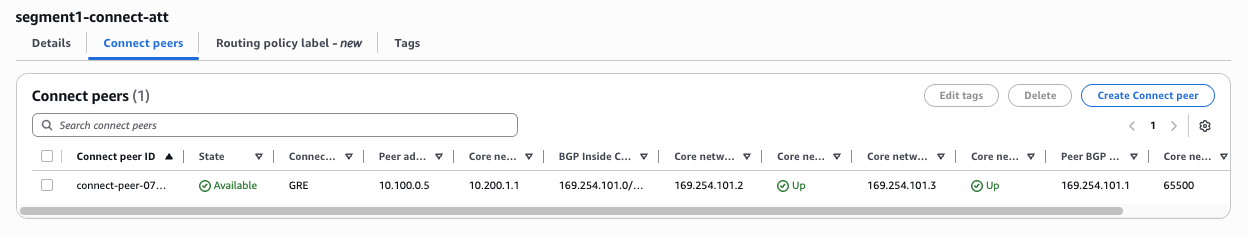
Figure 12: Verify Connect peer BGP Status
Verify that Segment1 route table on AWS Cloud WAN is learning routes for your remote site for VRF1 only.
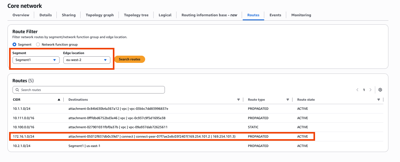
Figure 13: Verify Segment1 routes on AWS Cloud WAN
Verify BGP neighbor status on your SD-WAN virtual appliance; you should see that both your AWS Cloud WAN BGP neighbors are up and receiving routes.
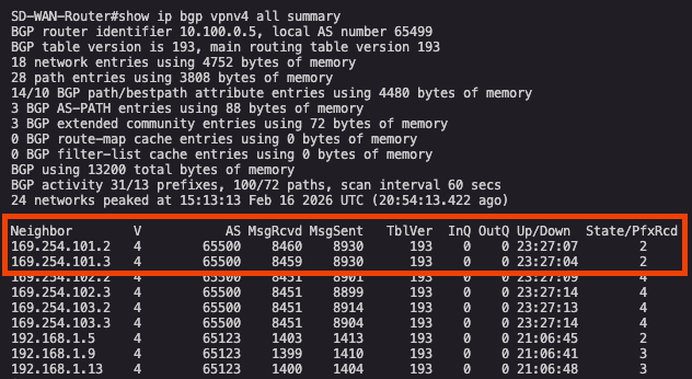
Figure 14: Verify BGP State on your SD-WAN appliance
Verify that your VRF (vrf1) on the SD-WAN appliance is receiving routes only for VPCs attached to Segment1 and not for any other VPCs. In Figure 14 below, 10.1.1.0/24 and 10.2.1.0/24 represent routes for VPCs attached to Segment1 in eu-west-2 and us-east-1. The other routes listed are for the remote site connected via an IPSec tunnels, over the internet into the SD-WAN appliance.
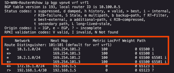
Figure 15: Verify BGP routes learnt from AWS Cloud WAN on SD-WAN appliance
This demonstrates that we have successfully maintained network segmentation from the remote site to the AWS Cloud WAN segment via the SD-WAN virtual appliance in AWS.
Considerations
- You can create up to four Connect peers per Connect attachment (up to 20 Gbps in total bandwidth per GRE-based Connect attachment).
- You can use Equal-Cost Multi-Path (ECMP) to get higher bandwidth by scaling horizontally across multiple Connect peers on the same Connect attachment or across multiple Connect attachments.
- The Core network cannot use ECMP between the BGP peering’s on the same Connect peer.
- Carefully evaluate bandwidth requirements across your WAN connectivity and AWS infrastructure. Verify that the Amazon EC2 instance type provides sufficient network bandwidth to support your expected throughput. EC2 Instance network performance varies significantly by type and size and can become a bottleneck if undersized.
Cleaning up
To remove the resources created in this post:
- Delete Connect Peers: Navigate to each Connect attachment and delete all Connect peers
- Delete Connect Attachments: Under Core network > Attachments, delete each Connect attachment
- Remove Segment Routes: Edit your AWS Cloud WAN policy and delete static routes to the Transport VPC
- Delete VPC Attachment: Remove the Transport VPC attachment
- Update Attachment Policies: Edit and remove the attachment policies, then apply the updated policy
- Remove SD-WAN Configuration: Delete BGP peering, GRE tunnels, and VRF configurations per vendor documentation
- Terminate Resources: Delete the SD-WAN appliance, Transport VPC, and any test resources
If you created a test AWS Cloud WAN core network, also ensure you terminate AWS Cloud WAN to avoid additional charges.
Conclusion
In this post, we demonstrated how the GRE-based Connect attachment model provides a reliable approach for extending SD-WAN segmentation into AWS Cloud WAN. By using GRE tunnels and multiple Connect attachments, you can maintain strict network isolation while benefiting from AWS global infrastructure and automation capabilities.
This model works best for enterprises that require a flexible way to apply granular control over routing. The ability to add new segments by configuring additional GRE-based Connect attachments makes this approach operationally efficient.
For organizations requiring higher bandwidth (up to 100 Gbps per Availability Zone), Part 2 of this series explores the Tunnel-less Connect approach with Multi-VPC ENIs (X-ENIs), which removes tunnel encapsulation entirely while maintaining end-to-end segmentation.