AWS for Industries
Dynamic Inbound Routing for BYOIP Workloads Using Amazon VPC Route Server
Managing large pools of public IPv4 addresses in AWS presents a common operational challenge: how do you route inbound internet traffic reliably through a network appliance — such as a firewall or traffic inspection device — without manual intervention when that appliance fails?
Organizations that use Bring Your Own IP (BYOIP) address pools often need to direct all inbound traffic through a centralized appliance for inspection, policy enforcement, or security monitoring. Amazon Virtual Private Cloud (Amazon VPC) supports this through internet gateway (IGW) ingress routing, which lets you route traffic entering your VPC — destined for a BYOIP pool — to a specific elastic network interface before it reaches its destination. This eliminates the need for complex address translation on inbound connections.
The challenge is resilience. Traditional static routing creates a significant operational risk: when a network appliance fails, static routes continue pointing to the failed instance until an operator manually updates the route table. Recovery can take minutes to hours, increasing downtime and the risk of human error.
Amazon VPC Route Server is a managed service that enables dynamic routing within your VPC using Border Gateway Protocol (BGP). It establishes BGP-speaking endpoints in your VPC subnets, allowing network appliances to peer directly with these endpoints to advertise routes and automatically update VPC route tables. With support for Bidirectional Forwarding Detection (BFD), it provides rapid failure detection and automated traffic rerouting — eliminating the manual configuration overhead and risk of human error associated with static routing.
In this post, we show you how to use Amazon VPC Route Server with dynamic Border Gateway Protocol (BGP) routing to automate failover for BYOIP workloads. This solution is designed for workloads that route large public IP pools through network appliances in AWS, including security inspection pipelines, IoT platforms, media delivery networks, and firewall deployments. Telecommunications operators managing large subscriber IP pools will also find this pattern directly applicable.
Prerequisites
Before you begin, make sure you have the following:
- Familiarity with routing concepts and how network appliances process inbound traffic
- Experience with AWS networking services, including Amazon VPC, route tables, and elastic network interfaces
- AWS Command Line Interface (AWS CLI) installed and configured, or access to the AWS Management Console
- Basic knowledge of AWS CloudFormation for deploying and managing infrastructure as code
- Important: This walkthrough creates AWS resources that incur costs, including Amazon Elastic Compute Cloud (Amazon EC2) instances, an Amazon VPC Route Server, and Route Server endpoints. For pricing details, see Amazon VPC pricing and Amazon EC2 pricing. Remember to delete all resources after testing to avoid ongoing charges.
Solution Overview
Amazon VPC Route Server provides dynamic routing capabilities within your VPC using Border Gateway Protocol (BGP). Network appliances establish BGP sessions with VPC Route Server endpoints and advertise IP prefixes with specific attributes. When a failure occurs, BGP automatically withdraws routes and reconverges to healthy paths — updating your VPC route tables without manual intervention. Recovery time drops from minutes to seconds.
Key Benefits
- Automatic failover: Sub-second failure detection with Bidirectional Forwarding Detection (BFD)
- Reduced operational overhead: No manual route table updates during failures
- Scalability: Supports multiple IP pools and network appliances
- Standards-based: Uses industry-standard BGP and BFD protocols
How Dynamic Routing Eliminates Single Points of Failure
This solution deploys two network appliances across separate Availability Zones. Each appliance establishes BGP sessions with VPC Route Server endpoints in their respective subnets. Both appliances advertise the same BYOIP prefixes, but the active appliance uses a shorter AS Path to ensure BGP prefers its routes.
With static routing, the internet gateway route table points directly to a single network appliance elastic network interface:
IGW Route Table (static):
[BYOIP_PREFIX] → eni-xxxxx (active appliance)
If the active appliance fails, this route remains pointing to the failed elastic network interface until someone manually updates it — leaving traffic dropped for minutes to hours.
With dynamic routing through VPC Route Server, this manual step is eliminated. When the active appliance fails, BGP detects the loss and reconverges automatically to the standby appliance — updating the internet gateway route table within seconds.
The following architecture diagram shows active and standby network appliances peering with VPC Route Server endpoints, with automatic route propagation to the internet gateway and VPC route tables:
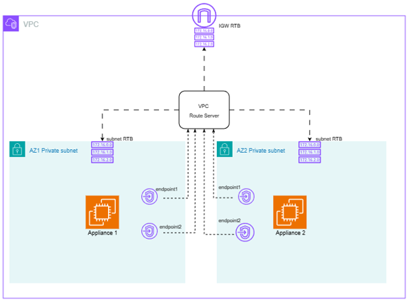
Figure 1: Architecture diagram — Active and standby appliances peering with VPC Route Server endpoints, IGW association
Key Architecture Components
- Two appliances across different AZs (instance-rs-az1, instance-rs-az2)
- Four Route Server Endpoints (2 per subnet for redundancy)
- BGP peering between appliances and Route Server Endpoints
- Automatic route propagation to both VPC route table and IGW route table
- AS Path manipulation for path preference (active uses short path, standby uses long path)
How It Works
Active Appliance (AZ1):
- Advertises [BYOIP_PREFIX] with AS Path: 65001
- Maintains BGP sessions with RSE1 and RSE2
Standby Appliance (AZ2):
- Advertises [BYOIP_PREFIX] with AS Path: 65001 65001 (longer path, lower preference)
- Maintains BGP sessions with RSE3 and RSE4
VPC Route Server:
- Receives both advertisements
- Selects the active appliance route (shorter AS Path wins)
- Propagates to IGW route table: [BYOIP_PREFIX] → eni-active
- Propagates to VPC route table: [BYOIP_PREFIX] → eni-active
Automatic Failover Process
When the active appliance fails, the following sequence occurs automatically:
- Failure detection — BGP keepalive timeout or BFD
- Route withdrawal — VPC Route Server marks the BGP session as DOWN
- Reconvergence — The standby route becomes the best path
- Route table update — Both IGW and VPC route tables update automatically
- Traffic restoration — Traffic flows to the standby appliance
Deploy the solution
You can deploy this solution using the AWS CloudFormation template available in the aws-samples repository.
Note: This walkthrough uses a private loopback IP address (172.16.1.1/32) to demonstrate inbound routing behavior without requiring a provisioned BYOIP pool. The prefix 198.51.100.0/23, visible in the BGP and Route Server outputs, represents a sample BYOIP prefix to illustrate how a real public IP pool would appear alongside the demo configuration. The routing mechanics — BGP peering, AS Path preference, route propagation, and automatic failover — work identically regardless of whether the advertised prefix is private or public.
To move from this demo to a production BYOIP deployment, you need to:
- Provision your BYOIP address pool and advertise it to AWS (see Bring your own IP addresses (BYOIP)).
- Associate the BYOIP pool with your internet gateway.
- Update the GoBGP configuration (or your network appliance) to advertise your BYOIP CIDR instead of the demo loopback address.
All other components — Route Server, BGP peering, AS Path manipulation, and failover behavior — remain unchanged.
What the template creates
The CloudFormation template deploys the following resources:
- A VPC (10.0.0.0/16) with three subnets across two Availability Zones
- An internet gateway with an associated edge route table
- An Amazon VPC Route Server (Autonomous System Number (ASN) 65000) with four endpoints (two per Availability Zone)
- Two Amazon EC2 instances (t4g.micro, Amazon Linux 2023) acting as network appliances, each running GoBGP v3.36.0
- One access instance for testing connectivity
- BGP peering between each appliance and its local Route Server endpoints
- Route propagation to both the VPC route table and the internet gateway route table
- An AWS Identity and Access Management (IAM) role with Session Manager, a capability of AWS Systems Manager access for secure instance connectivity
- A security group allowing BGP (TCP port 179) and ICMP within the VPC
Launch the stack
You can deploy the stack using either the AWS Management Console or the AWS CLI.
Option 1: AWS Management Console
- Sign in to the AWS CloudFormation console.
- Choose Create stack.
- Choose With new resources (standard).
- For Template source, choose Upload a template file.
- Choose file.
- Select the downloaded template file.
- Choose Next.
- For Stack name, enter a name such as
route-server-byoip-demo. - Choose Next on each remaining configuration page, accepting the default values.
- Choose Submit.
Option 2: AWS CLI
aws cloudformation create-stack \
  --stack-name route-server-byoip-demo \
  --template-body file://IR_RS_CF.yaml \
  --capabilities CAPABILITY_IAM
The CAPABILITY_IAM flag is required because the template creates an IAM role for Systems Manager access.
Wait for deployment to complete
The stack takes approximately 5–10 minutes to deploy. You can monitor progress in the CloudFormation console under the Events tab.
When the stack status shows CREATE_COMPLETE, the Outputs tab displays the IP addresses of all four Route Server endpoints. Note these for verification in the next section.
Walkthrough
The steps and screenshots below help in understanding the solution deployed using the sample CloudFormation template.
From the console, navigate to Amazon VPC and select ‘Route Servers’ from the left sidebar. Check the Route Server Endpoints from the VPC Route Server:
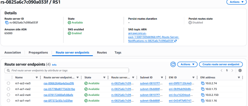
Figure 2: VPC Route Server endpoints in the AWS Console
Open the ‘Routes’ tab and check routes installed by the Route Server:
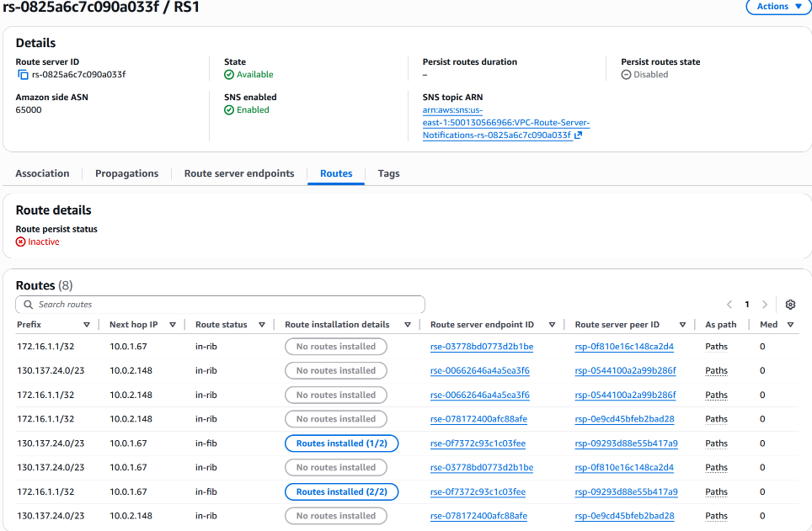
Figure 3: Routes installed by the Route Server
BGP Peering
The open-source BGP tool GoBGP is used to establish BGP peering between appliances and Route Server. Access the instances using Session Manager. Inspect the GoBGP configuration from one of the appliance instances (/home/ec2-user/gobgpd.conf).
Check the BGP session establishment and advertised routes from the appliance instances.
From network appliance 1:
sh-5.2$ sudo /home/ec2-user/gobgp neighbor
Peer         AS  Up/Down State       |#Received  Accepted
10.0.1.16 65000 02:41:38 Establ      |        0         0
10.0.1.73 65000 02:41:39 Establ      |        0         0

sh-5.2$  sudo /home/ec2-user/gobgp global rib
   Network              Next Hop             AS_PATH           Age        Attrs
*> 198.51.100.0/23      0.0.0.0                               00:03:41   [{Origin: ?}]
*> 172.16.1.1/32        0.0.0.0                               02:41:48   [{Origin: ?}]
From network appliance 2:
sh-5.2$  sudo /home/ec2-user/gobgp neighbor
Peer          AS  Up/Down State       |#Received  Accepted
10.0.2.74  65000 03:00:02 Establ      |        0         0
10.0.2.150 65000 03:00:02 Establ      |        0         0

sh-5.2$ sudo /home/ec2-user/gobgp global rib
   Network              Next Hop             AS_PATH           Age        Attrs
*> 198.51.100.0/23      0.0.0.0              65001 65001      00:03:30   [{Origin: ?}]
*> 172.16.1.1/32        0.0.0.0              65001 65001      03:04:57   [{Origin: ?}]
Figure 4: IGW route table showing BGP-propagated route to active appliance
Ingress Routing
From the IGW Route Table, perform edge association with the IGW as shown below. Verify that the IGW route table does not have any subnets associated from the ‘Subnet associations’ tab.
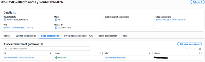
Verify that the route table reflects the BGP-propagated route pointing to the active appliance from AZ1:
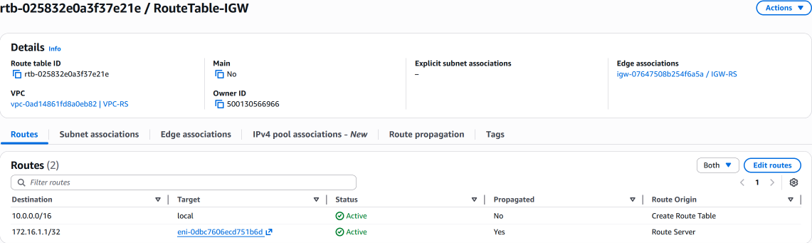
Figure 5: IGW route table after failover — traffic routed to standby appliance
Failover Verification
When network appliance 1 fails or its connection fails, BGP with BFD detects the failure and the route is immediately withdrawn from the IGW route table. A new route towards the standby appliance is updated automatically. Note the target ENI change in Figure 6 from Figure 5.
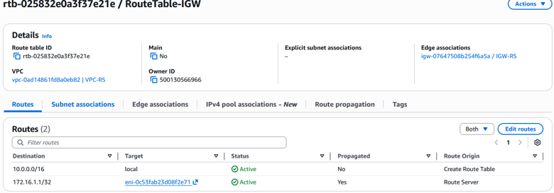 Figure 6: IGW route table after failover — traffic routed to standby appliance
Cleanup
To avoid ongoing charges, delete the resources you created in this walkthrough.
To delete the CloudFormation stack:
- Open the AWS CloudFormation console.
- Select the stack you deployed from the aws-samples repository.
- Choose Delete.
- Confirm the deletion when prompted.
CloudFormation removes the following resources automatically:
- VPC and networking components (subnets, route tables, and route table associations)
- Amazon EC2 instances (instance-rs-az1, instance-rs-az2, and access instance)
- VPC Route Server and associated resources (endpoints, association, propagation, and peers)
- Internet Gateway and VPC Gateway Attachment
- Security groups
- IAM role and instance profile for Systems Manager access
To remove the BYOIP pool association:
If you have associated a BYOIP address pool with the Internet Gateway for this walkthrough, disassociate it before deleting the stack. For instructions, see Bring your own IP addresses (BYOIP) in Amazon EC2.
Note: Verify that all resources have been deleted in the AWS Management Console to confirm no charges continue to accrue.
Conclusion
In this post, you deployed a dynamic ingress routing solution using Amazon VPC Route Server and BGP. You configured two network appliances with AS Path manipulation to establish active-standby failover, and verified that route propagation updates the internet gateway route table automatically when an appliance fails.
You can extend this architecture further by enabling active-active routing with equal-cost paths, tuning BFD timers for sub-second failure detection, or scaling to multiple BYOIP prefixes. Combine Route Server SNS notifications with Amazon CloudWatch alarms and VPC Flow Logs to monitor BGP session health and track traffic shifts during failover events.
To get started, deploy the solution using the aws-samples repository and adapt it to your BYOIP pool configuration.
Have questions or feedback? Leave a comment below or contribute to the repository on GitHub. We’d love to hear how you’re using Amazon VPC Route Server in your environment.