Migration & Modernization
Dive Deep into the AWS Transform Network Migration Agent: Hub and Spoke Network Setup
Introduction
Network design takes real effort in any migration. You need to map source network segments to VPCs, plan subnets across Availability Zones, translate firewall rules into security groups, and configure route tables that keep traffic flowing, a challenge the AWS Transform – Migrations network migration agent solves for you. You upload exports from well-known SDN or firewall vendors, and AWS Transform translates the source network segments to Amazon Virtual Private Cloud (Amazon VPC), subnets and security groups. You review the result and refine it through chat before anything is provisioned, a workflow covered here.
In this post, we walk through what you customize after the agent deploys a hub and spoke generated topology, so you end up with a production-ready network.
Prerequisites
This post assumes you have an AWS account with permissions to create and manage VPCs, subnets, route tables, Transit Gateway, and firewall resources. You should have already completed an AWS Transform network migration that deployed a hub and spoke topology; if you haven’t run one yet, see the AWS Transform documentation to get started. Familiarity with core AWS networking concepts such as VPCs, subnets, route tables, and Transit Gateway will help you follow along. Depending on your inspection strategy, you may also need access to AWS Network Firewall or a third-party firewall appliance from AWS Marketplace.
Hub and spoke network topology
During the network migration planning, the agent asks you to choose a network topology. Isolated VPCs keeps each VPC independent with no routing between them. Hub and Spoke connects every VPC through an AWS Transit Gateway and adds dedicated Inspection, Inbound, and Outbound VPCs, so cross-VPC traffic can be centrally inspected. It is the recommended choice when you need centralized inspection.
When you choose Hub and Spoke, AWS Transform creates the following:
- Spoke VPCs. One VPC for each detected source network segment, with private subnets and a Transit Gateway attachment.
- Inspection VPC. The VPC that will host your firewall, with every cross-VPC flow routed through it. AWS Transform turns on appliance mode for this attachment, which keeps both directions of a connection on the same firewall endpoint.
- Inbound VPC. Handles traffic arriving from the internet, with an internet gateway and public subnets across multiple Availability Zones.
- Outbound VPC. Handles traffic leaving for the internet, with an internet gateway, NAT gateways and Elastic IP addresses per Availability Zone, and private subnets for the Transit Gateway attachment.
- Two Transit Gateway route tables. The Uninspected table is associated with the spoke, Inbound, and Outbound VPCs and sends all traffic to the Inspection VPC. The Inspected table carries the propagated spoke routes that deliver traffic onward.
- Security groups. Your source firewall policies arrive translated into security groups. The permissions you add in this post cover the cross-VPC and internet paths a flat network never had to describe.
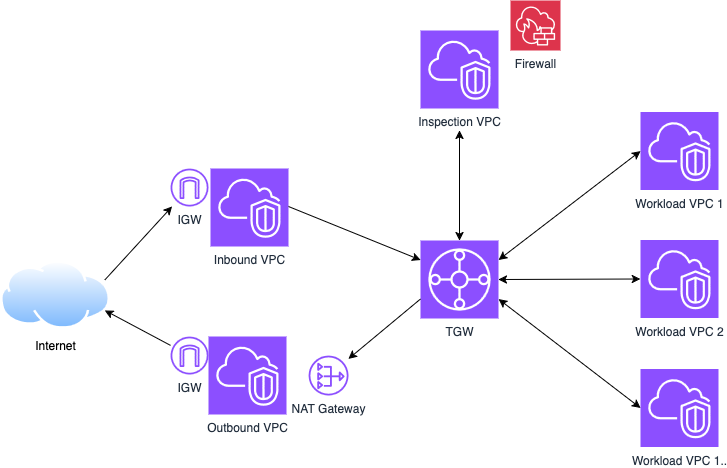
Figure 1. The Hub and Spoke topology that AWS Transform deploys, with an AWS Transit Gateway hub connecting the spoke VPCs and the dedicated Inspection, Inbound, and Outbound VPCs.
Customizing your hub and spoke setup
The AWS Transform documentation lists what’s left under Complete your setup. These steps are intentionally yours because they encode your security posture: who talks to whom, what gets inspected, and what reaches the internet.
Every flow follows the same pattern: traffic leaves a spoke via the Uninspected route table, enters the Inspection VPC where your firewall examines it, and exits on the Inspected route table toward its destination, another spoke, the Outbound VPC, or the Inbound VPC.
Two behaviors are worth knowing first. Route propagation advertises VPC CIDR ranges only, so any default route you need is one you create yourself. And every path needs a matching return path.
Step 1: Extend and resolve names in your network
If your migration includes a hybrid period with AWS Direct Connect or VPN, attach that gateway to the Transit Gateway and add routes for your on-premises ranges. For name resolution between spokes or back to on-premises, set up Amazon Route 53 Resolver endpoints. The specifics depend on your environment, so this post focuses on the hub and spoke flows only.
If all your workloads are in AWS and need to resolve the same private domain, associate a single Route 53 Private Hosted Zone with each spoke VPC. No Resolver endpoints are needed for this; association alone enables resolution across all the VPCs.
Step 2: Deploy a firewall in the Inspection VPC
AWS Transform creates subnets in the Inspection VPC for the Transit Gateway attachment only. Your firewall sits between the Uninspected and Inspected route tables, receiving traffic from one and returning it to the other. You can use AWS Network Firewall or a third-party appliance from AWS Marketplace.
If you use AWS Network Firewall, you can attach it directly to the Transit Gateway as a network function attachment, no Inspection VPC subnets or VPC-level routing required. This approach replaces the Inspection VPC that AWS Transform deployed; if you choose this path, that VPC and its Transit Gateway attachment are no longer needed. Start with a default-deny policy and add stateful rules only for the flows your workloads actually need. Turn on logging before you test; the alert log shows whether traffic was dropped by policy or never reached the firewall. See Transit Gateway network function attachments and the rule group documentation for the full syntax.
- If you use a third-party appliance from AWS Marketplace, deploy it in the Inspection VPC using the following steps.
- Create firewall subnets. Add one dedicated subnet per Availability Zone in the Inspection VPC, each holding the appliance endpoint for that zone. Keep them separate from the Transit Gateway attachment subnets.
- Deploy the appliance in those subnets according to the vendor’s documentation.
- Route inbound traffic to the appliance. In the route table associated with the Transit Gateway attachment subnets, add a route for 0.0.0.0/0 that targets the appliance endpoint in the same Availability Zone.
- Route inspected traffic back to the Transit Gateway. In the route table associated with the firewall subnets, add routes for your spoke CIDR ranges that target the Transit Gateway attachment.
Keep the routing Availability Zone local. Traffic entering in one zone should reach the firewall endpoint in that same zone, which avoids cross-zone charges and keeps flows symmetric.
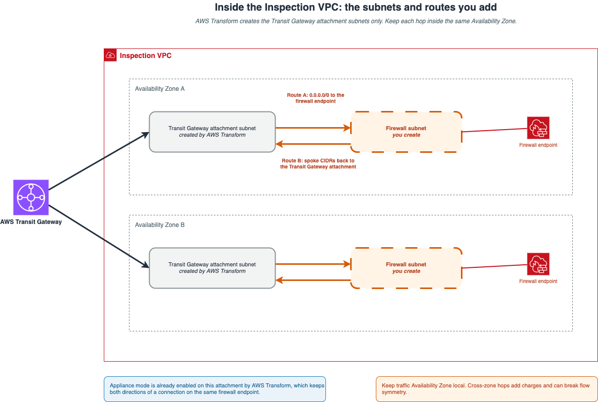
Figure 2. Inside the Inspection VPC. Traffic arriving from the Transit Gateway routes to the AWS Network Firewall endpoint in the same Availability Zone, then returns to the Transit Gateway after inspection.
Step 3: Allow east-west traffic between spoke VPCs
Say the workload in workload-a-vpc needs an API hosted in workload-b-vpc. The routing is already in place. Each spoke defaults to the Transit Gateway, the Uninspected route table sends that traffic to the Inspection VPC, and the Inspected route table delivers it onward. The reply retraces the same path, so confirm the rofuting rather than change it.
Your work is to permit the flow in the two places that deny it by default:
- Allow the flow in the firewall. Add the stateful rule that permits this specific source and destination pair.
Allow the flow in the security groups. Update the security group on the destination workload to accept traffic from the source CIDR range (or from the source security group, if you enable securityGroupReferencingSupport on the Transit Gateway and VPC attachment). - The pattern repeats for every pair of spokes that needs to communicate. Because the default action drops, adding a pair is an explicit decision.
Step 4: Turn on outbound internet access
Workloads in your spoke VPCs have no internet access by default. Traffic must traverse the inspection chain before reaching the Outbound VPC as per the following flow:
spoke VPC → Transit Gateway (Uninspected) → Inspection VPC → Transit Gateway (Inspected) → Outbound VPC → NAT gateway → internet gateway → internet
The Outbound VPC and its internet and NAT gateways are already in place. You wire it into the path with these routes:
- Route the Outbound public subnets to the internet gateway. In the Outbound VPC public route table, add 0.0.0.0/0 targeting the internet gateway.
- Add a default route to the Inspected route table. Point 0.0.0.0/0 at the Outbound VPC attachment. Route propagation never creates a default route, so internet-bound traffic leaving inspection has nowhere to go until you add this one.
- Add the return route to the Outbound public route table. Add a route for your spoke CIDR range targeting the Transit Gateway. The NAT gateway translates return traffic back to your private range, which then needs a path home.
- Add the return route to the Outbound private route tables. Every Outbound VPC route table with a NAT gateway route also needs a route for your spoke CIDR range pointing at the Transit Gateway.
Allow the egress in your firewall. Domain list rules work well to permit a named set of endpoints and drop the rest. If your spoke security groups restrict outbound traffic (the default allows all), update them to permit the destinations your workloads need.
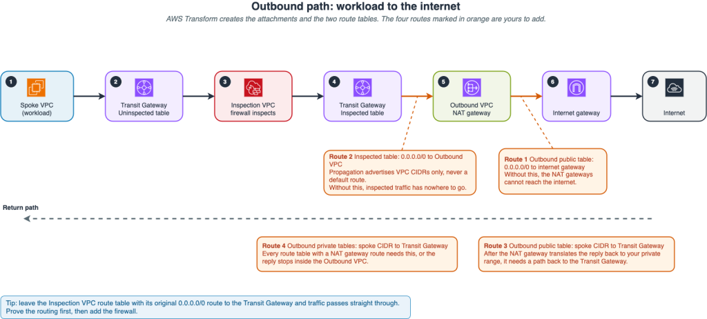
Figure 3. The outbound path from a workload to the internet, with the four routes you add marked at the points where they apply.
Step 5: Publish an application to the internet
Outbound access does not make your application reachable from the internet. For that you place an internet-facing entry point in the Inbound VPC and connect it to targets in your spokes.
internet → internet gateway → Inbound VPC → load balancer → Transit Gateway (Uninspected) → Inspection VPC → Transit Gateway (Inspected) → spoke VPC
- Create the entry point. Deploy it in the Inbound VPC public subnets across at least two Availability Zones. A Network Load Balancer or an Application Load Balancer both work, depending on the protocol your application needs.
- Connect it to your targets. Register targets by IP address, since the targets sit in a different VPC reached through the Transit Gateway. Alternatively, deploy an internal load balancer in the spoke VPC and register it as a target of an internet-facing NLB in the Inbound VPC (NLB supports ALB as a target type).
- Route the Inbound VPC toward the spokes. In the Inbound VPC subnet route tables, add routes for the destination spoke CIDR ranges that target the Transit Gateway attachment.
- Add a route for the Inbound VPC CIDR to the Inspected route table. Without it, reply traffic matches the default route from Part 4 and heads for the Outbound VPC instead of the load balancer. The symptom is a target that never turns healthy while the network looks correct.
- Allow the flow. Update the target security groups to accept traffic from the load balancer on your application port, and add the matching firewall inspection rule.
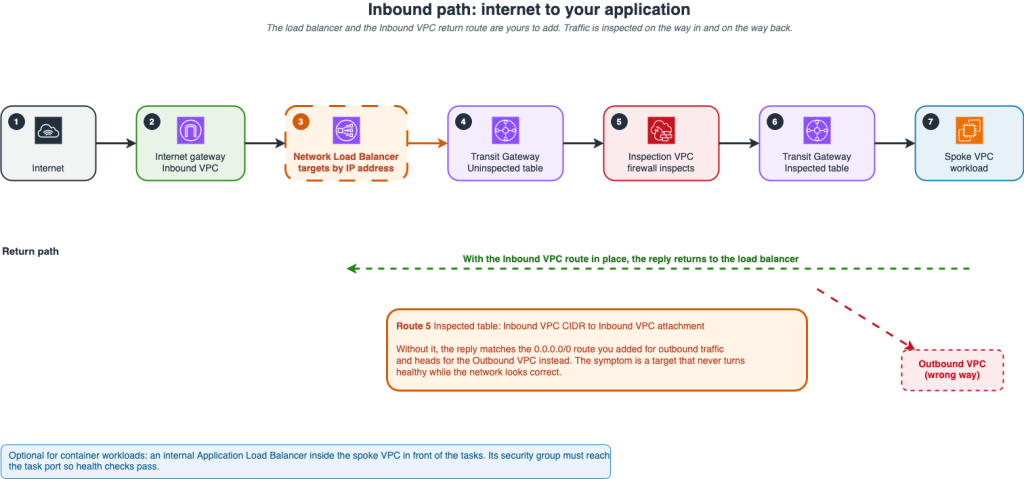
Figure 4. An internet-facing application published through the Inbound VPC, with traffic inspected in both directions and the return route that keeps replies on the right path.
Route summary
The following table lists summarizes every route you add, organized by location and the part that explains it.
| # | Route table | Destination | Target | Step |
|---|---|---|---|---|
| 1 | Inspection VPC, Transit Gateway attachment subnets | 0.0.0.0/0 | Firewall endpoint in the same Availability Zone | 2 |
| 2 | Inspection VPC, firewall subnets | Spoke CIDR ranges | Transit Gateway attachment | 2 |
| 3 | Outbound VPC, public subnets | 0.0.0.0/0 | Internet gateway | 4 |
| 4 | Transit Gateway, Inspected | 0.0.0.0/0 | Outbound VPC attachment | 4 |
| 5 | Outbound VPC, public subnets | Spoke CIDR ranges | Transit Gateway | 4 |
| 6 | Outbound VPC, private subnets | Spoke CIDR ranges | Transit Gateway | 4 |
| 7 | Inbound VPC, subnets | Destination spoke CIDR ranges | Transit Gateway attachment | 5 |
| 8 | Transit Gateway, Inspected | Inbound VPC CIDR | Inbound VPC attachment | 5 |
The following diagram shows the same entries from the perspective of each route table.
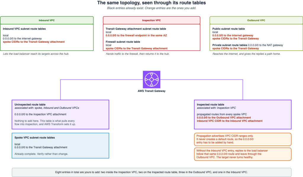
Figure 5. The same topology seen through its route tables. Entries in black already exist, and entries in orange are the ones you add.
Validate the network
Confirm the paths before you hand the network over. Reachability Analyzer traces a path between two spoke VPCs and names the component that blocks traffic when a path fails. Run it in both directions, because a one-way success usually means a missing return route.
Then test the real flows. A request from a spoke instance to a public endpoint proves the outbound path, including both return routes in the Outbound VPC. A healthy target on the load balancer proves the inbound path.
Finally, read the logs rather than trusting silence. Firewall logs should show approved flows as allowed and everything else as dropped. A quiet log usually means traffic is not arriving, so turn on VPC Flow Logs while you test.
Conclusion
In this post, you completed the setup of a hub and spoke network deployed by AWS Transform: deploying a firewall in the Inspection VPC, enabling east-west routing between spokes, wiring outbound internet access with return routes, and publishing an application to the internet through the Inbound VPC.
To get started, launch your own network migration in AWS Transform and select Hub and Spoke. The agent handles the baseline deployment, and you customize the routing and firewall inspection to match your security posture. The result is a production-ready network aligned with your business requirements from day one.