AWS HPC Blog
Cloud-native, high throughput grid computing using the AWS HTC-Grid solution
The Financial Service Industry (FSI) has traditionally relied on static, on-premises HPC compute grids equipped with third-party grid scheduler licenses to manage all of their computational needs, such as computing risk models, and addressing regulatory reporting requirements.
Three forces are putting a strain on these traditional models. First, the increased volatility in financial markets has exposed the fragility and lack of elasticity of many on-premises risk management systems and the HPC compute grids that support them. These systems are typically unable to scale to the capacity needed for rapid re-calculation of intra-day risk positions during volatile markets. Second, new regulations are expected to drive a three to tenfold increase in high performance computing (HPC) workloads, putting further strain on the systems. Last, pressure on margins is forcing FSI organizations to reduce operational costs and put limits on capital expenditure.
All of these combined are causing FSI organizations to extend on-premises grids to the cloud. Customers are increasingly looking to leverage the on-demand and burst-compute capabilities of AWS to maximize the performance and cost-benefits of managed, cloud-native services. Usually they start with a “lift & shift” approach, but quickly run into limitations and start asking “where to next?”. Ideally, customers want transparent scaling of resources based on the workload requirements, all at low cost.
To address these challenges, we worked with our FSI customers to develop an open-source, scalable, cloud-native high throughput computing solution on AWS, AWS HTC-Grid. HTC-Grid is being released within the AWS Labs umbrella as a self-managed and self-supported solution you can deploy in your AWS account. HTC-Grid allows users to submit large volumes of short and long running tasks, as well as to scale environments dynamically, according to business demand.
In this first blog of a two-part series, we describe the structure of HTC-Grid and its objective to provide a configurable blueprint for organizations that wish to move on from traditional HPC grid scheduling middleware and achieve the benefits of going cloud-native.
Design Tenets
HTC-Grid’s design tenets have been molded by the requirements of early adopters and by recurring themes observed across AWS customers.
- Scale and high throughput: To meet the most demanding of FSI risk environments, achieve a provisioning capacity of >100,000 nodes across multiple AWS Regions, with a throughput per AWS Region of >10,000 tasks per second (TPS).
- Low latency: Support sustained compute task throughput of >10,000TPS and ensure low infrastructure latency (~0.3s), to efficiently support short duration tasks (~1s) without batching.
- On-demand: The ability to have dedicated services on-demand (e.g., for overnight batch workloads), or for volatile intra-day workloads aligned to specific trading desks or individual power users.
- Modular: Not all workloads have the same requirements. Different workloads may benefit from different infrastructure performance/costs optimizations, hence a composable extensible architecture is required. This is enabled via interchangeable implementations of the Data and Compute Planes through “Infrastructure as Code”.
- Simplify migration: Support client API’s that are familiar to AWS customers.
- All compute looks like Lambda: Task API’s are implemented as AWS Lambda functions, irrespective of the backend compute resource being used (AWS Lambda service, Containers, or Amazon EC2).
- Cloud-native: Fully leverage operationally hardened AWS core services to optimize robustness and performance while minimizing operational management.
Collectively, these tenets deliver an operationally agile, on-demand solution, that can be rapidly tailored to specific business needs, yet having the operational scale and throughput to deal with the most demanding of FSI workloads.
HTC-Grid’s Architecture
As shown in Figure 1, HTC-Grid’s asynchronous architecture is comprised of four primary elements: the HTC-Grid Connector Library (GCL) for client applications, the Data Plane, Control Plane, and Compute Plane. These components interact with each other as follows:
- A Client Application uses the GCL to submit tasks. Each task is comprised of a task definition and the task payload.
- The payload of a task is the data associated with the task that needs to be passed to the execution process. The payload is loaded into the Data Plane.
- The definition of a task is a JSON record that contains metadata. It defines both how to schedule the task, and the client’s supplied commands – which define how to launch the task. The definition is loaded into the Control Plane:
- The task definition is registered with the Control Plane implemented using Amazon DynamoDB.
- The task definition is placed on the Control Plane queue using Amazon SQS.
- Each idle HTC-Grid Agent pulls a task from the Control Plane task queue if there is one available.
- The Agent retrieves the corresponding task’s payload from the Data Plane and commences calculation – the task is invoked as a local Lambda in the collocated Lambda container.
- Upon completion, the Agents write the result to the Data Plane.
- Throughout the task process lifecycle, each Agent maintains a status heart-beat with the DynamoDB registered task.
- The GCL is notified upon task completion.
- Upon notification, the GCL pulls the results from the Data Plane, returning these to the client.
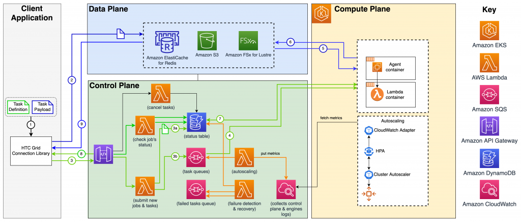
Figure 1: AWS HTC-Grid’s architecture.
The initial HTC-Grid production deployments have been configured to use Amazon EKS for the Compute Plane and Amazon ElastiCache for the Data Plane. However, the use of Amazon FSx for Lustre (Data Plane), and Amazon ECS, Amazon EC2 or the AWS Lambda service (Compute Plane) are valid alternatives that are currently being tested.
Task Definition
The GCL allows client applications to submit a single task or a vector of tasks. The tasks can take any serializable form, and are grouped before submission into a vector. Each submission of a task or a group of tasks generates a system-wide unique Session Id. Receiving a Session Id indicates a successful submission: all tasks associated with this session have been queued and will eventually be run. Task execution is performed asynchronously. The HTC-Grid client may either (i) re-use the returned Session Id to submit more tasks (i.e. a batch of tasks), (ii) wait for the results of the last submitted session, or (iii) asynchronously submit more sessions. The following code snippet shows a simple usage example, using GCL to submit an array of tasks.
from api.connector import AWSConnector

import os
import json
import logging

client_config_file = os.environ['AGENT_CONFIG_FILE']

with open(client_config_file, 'r') as file:
client_config_file = json.loads(file.read())


if __name__ == "__main__":

logging.info("Simple Client")
gridConnector = AWSConnector()

gridConnector.init(client_config_file, username=username, password=password)
gridConnector.authenticate()

task_1_definition = {
"worker_arguments": ["1000", "1", "1"]
}

task_2_definition = {
"worker_arguments": ["2000", "1", "1"]
}

submission_resp = gridConnector.send([task_1_definition, task_2_definition])
logging.info(submission_resp)

results = gridConnector.get_results(submission_resp, timeout_sec=100)
logging.info(results)
The Data Plane
The Data Plane is designed to handle data transfer, and can be used to pass any type of required data specific to the task’s execution (e.g. arguments to be passed to the executable, static libraries, etc.), and to store the task’s output. The persistence service may be used for the duration of the computation only, in which case a caching implementation can work well, or could also be used to preserve historical data. HTC-Grid currently supports four Data Plane implementations: S3, Redis, S3-Redis Hybrid where Redis is used as a write-through cache, and FSx for Lustre. The Data Plane does not have a data retention mechanism – though S3 data lifecycle policies can be applied to reduce the cost. If required, large amounts of common input data can be preloaded into the Data Plane, prior to the workload execution.
The Control Plane
The Control Plane is responsible for queuing and scheduling tasks submitted by each client – for execution on the next available computational slot – retrying tasks that fail, and scaling the grid according to the load. Using the GCL, a client invokes the Submit Tasks Lambda function via an HTTPS request. The Submit Tasks Lambda iterates over the list of submitted tasks (all tasks in the session) and creates:
- A single row in the DynamoDB state table per task (see Figure 1: marker 3a).
- A corresponding entry in SQS (see Figure 1: marker 3b).
Note, the insertions sequence is important to avoid a race condition. As shown in the following DynamoDB state table extract, each row contains a set of attributes associated with the task’s definition.
| Column Name | Sample Values | Comment |
session_id |
“6398f57e-6911-11eb-b5fb” |
Globally unique UUID |
task_id |
“6398f57e-6911-11eb-b5fb_1” |
Globally unique UUID. “_1” identifies task Id. |
submission_timestamp |
1628537731341 |
The time when the task has been submitted and the time when execution finished. Both fields are used for monitoring and bookkeeping purposes. (epoch time in ms). 0 value for the task_completion_timestamp indicates that the task is still in flight. |
task_completion_timestamp |
0 |
|
task_state |
Pending, Running, Finished, or Failed |
A state of the task |
task_owner |
htc-agent-757c85c6c7-z82t9 |
The Id of the Agent that picked up the task |
retries |
0 |
The number of times this task has been retried |
task_definition |
{…} |
Tasks metadata |
sqs_handler_id |
MbZj6wDWli+Jvww JaBV+3dcjk2YW2vA … |
Set by the Agent when the task is pulled from SQS. The handler is used to control the visibility of the associated SQS message in case of failure recovery |
heartbeat_expiration_timestamp |
1630321516719 |
The timestamp in the future when Agent and Lambda worker will be considered failed. |
On insertion into DynamoDB, a task record’s initial state is set to Pending. The state tables define the single source of truth for each task in the system. After recording task’s state, the Submit Tasks Lambda sends a copy of the task’s definition to the SQS task queue. At this point, tasks become available for execution. Each Agent runs an event loop to check for tasks in the designated SQS queue. The next available task is pulled and the task’s state is updated to Running. Upon completion, the Agent changes the task state to Finished. Because a standard SQS queue (not FIFO) is used, message reordering can occur, and while more-than-once delivery may happen as well (very infrequently) , the scheduler reconciles such duplicates.
The Compute Plane
This section outlines an HTC-Grid deployment, configured with the Compute Plane running on Amazon EKS, pictured in Figure 2.

Figure 2: AWS HTC-Grid’s Amazon EKS-based Compute Plane
In this configuration, Agents and Lambda Functions are treated as a Kubernetes deployment, a fixed number of pods that will be provided to run on the created (quiescent baseline sized) EKS cluster. Scaling behavior from the baseline is then controlled by the Autoscaling Lambda (part of the Control Plane in Figure 1) which regularly checks the size of the SQS task queue and triggers the appropriate adjustment to the number of nodes (Figure 3) utilized by the Kubernetes cluster. The CloudWatch Adapter exposes the Kubernetes API so that the default Horizontal Pod Autoscaler (HPA for short) can access metrics stored in CloudWatch by the auto scaling Lambda. The Pod Autoscaler (using HPA) adds/removes pods based on these CloudWatch metrics. Finally, the Cluster Autoscaler adds/removes EC2 instances based on the resource reservation or usage.

Figure 3: A flow chart outlining the Compute Plane’s scaling-out process.
The corresponding scale down process is shown in Figure 4. The process of scaling down pods is triggered when the task queue’s metrics indicate a target cluster size that is smaller than the current cluster size. In response, the Kubernetes control plane sends a SIGTERM signal to selected containers/pods. The SIGTERM is intercepted by Agents, providing the opportunity to finish the current task and exit gracefully. The pod terminates after the Agent exits, or once the terminationGracePeriod has expired. Instance scale down then occurs, targeting inactive instances.
Note that for the current HTC-Grid release, the TerminationGracePeriod is set to be longer than the internal time out of the Agent (by default 1 hour), ensuring that the Agent can terminate a running task.

Figure 4: A flow chart outlining the Compute Plane’s scaling-in process.
Conclusion
In this blog, we introduced the key components and processes that form the AWS HTC-Grid solution. We demonstrated how a high throughput grid scheduler can be built using serverless and fully managed cloud services on AWS. We have released HTC-Grid as an AWS Labs project. Like all AWS Labs projects, it is worth mentioning that HTC-Grid is open source (Apache 2.0 License), and not a supported AWS Service offering.
Our next post will go into more depth on the operational and performance characteristics of the AWS HTC-Grid solution.
To learn more and start experimenting with AWS HTC-Grid, please refer to the git repository at https://github.com/awslabs/aws-htc-grid. You can also try our AWS HTC-Grid yourself, refer to the AWS HTC-Grid workshop.