AWS for Industries
CME Group MDP multicast data access on AWS using Transit Gateway
Financial institutions migrating to AWS face challenges receiving multicast data: CME Group Market Data Platform (MDP) delivers market data through multicast feeds, but Amazon Virtual Private Cloud (Amazon VPC) does not currently support native multicast distribution without additional configuration. Without a multicast-capable architecture, you must replicate data through complex unicast workarounds that might increase cost, and operational overhead. AWS Transit Gateway multicast domains and Cisco Catalyst 8000V virtual routers solve this by providing native multicast data access on AWS. This approach simplifies your infrastructure, distributes data to multiple receivers as your needs grow, and keeps latency low for trading applications.
This post shows you how to design an architecture that receives CME Group MDP multicast data on AWS, then deploy and configure the solution with setup steps. You’ll also test and observe both throughput and latency metrics across AWS Transit Gateway and the entire data path, and configure Cisco Catalyst 8000V virtual routers as multicast bridges between on-premises and AWS environments.
Prerequisites
Before you implement this solution, verify that you have the following:
- An active AWS account with permissions to create Amazon VPC, Amazon EC2 instances, and AWS Transit Gateway resources
- 300 above knowledge level with networking concepts including multicast, GRE tunnels, Protocol Independent Multicast (PIM), and Open Shortest Path First (OSPF)
- Experience with AWS CLI (version 2.x or later) installed and configured with appropriate credentials
- A subscription to Cisco Catalyst 8000V on AWS Marketplace
- (For production deployments) AWS Direct Connect or Site-to-Site VPN connectivity to the CME Group MDP data center
Solution architecture
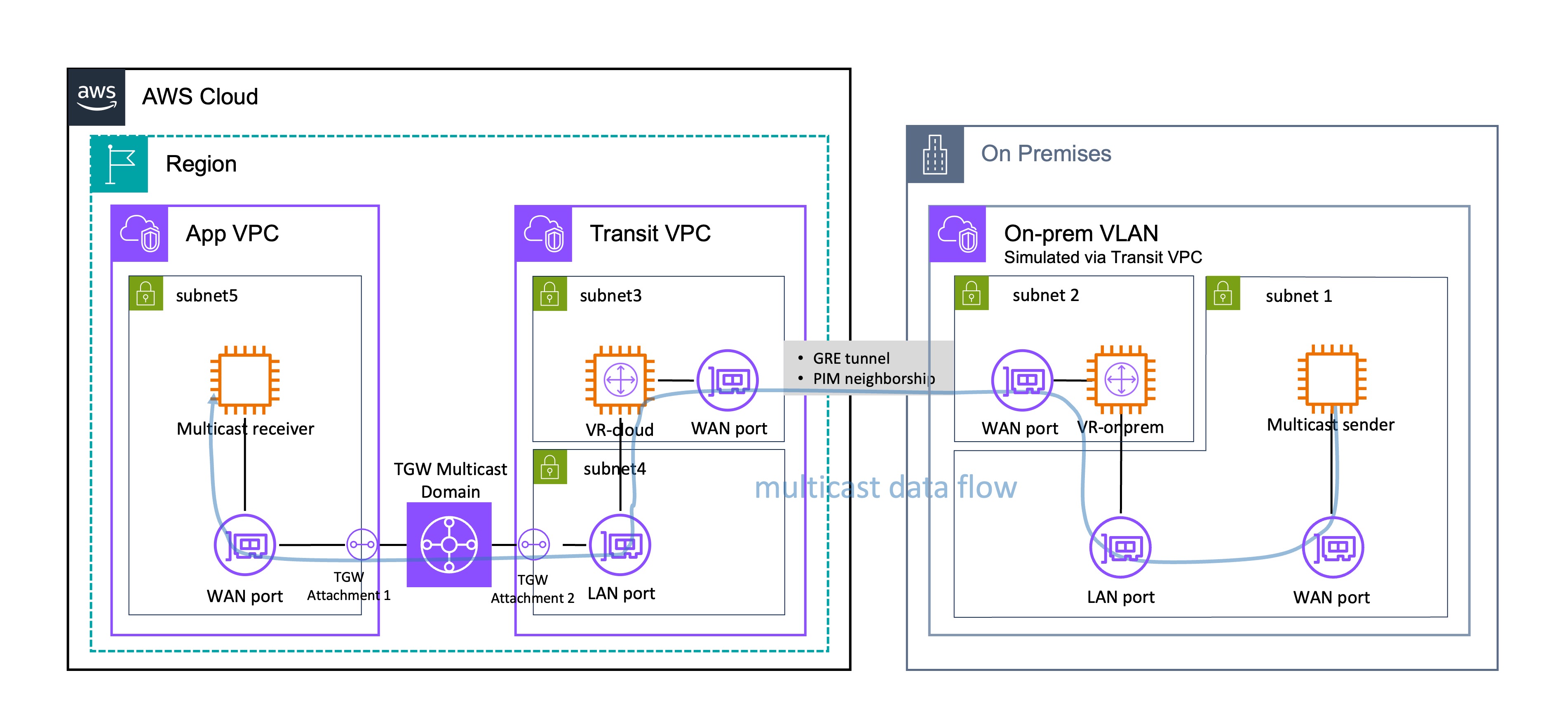
Figure 1: Solution architecture for CME Group MDP multicast data access on AWS using Transit Gateway.
You need three main components to receive CME Group MDP multicast data on AWS: an on-premises environment (simulated in AWS for this walkthrough), a Transit VPC that hosts the multicast bridge routers, and an Application VPC (App VPC for short) that hosts your multicast receivers.
Your multicast data flows from the sender through VR-onprem through a GRE tunnel, then to VR-cloud, through the TGW multicast domain, and finally to your receivers in the App VPC.
This walkthrough simulates an on-premises environment within AWS. Subnet 1 houses the multicast sender, which represents the multicast data source. Subnet 2 contains VR-onprem (virtual router, on-premises), which serves as the on-premises anchor point for the hybrid multicast solution. The sender connects to VR-onprem through both its WAN port and VR-onprem’s LAN port.
You can connect your on-premises environment to AWS through AWS Direct Connect (recommended for production) or a VPN connection (recommended for test/POC). AWS has established an AWS Direct Connect location within the CyrusOne Aurora data center in Aurora, Illinois, making it possible to set up AWS Direct Connect between CME Group’s data center and the AWS Ohio Region through cross-connect. AWS Direct Connect location within the CyrusOne Aurora data center in Aurora, Illinois
A GRE (Generic Routing Encapsulation) tunnel with PIM (Protocol Independent Multicast) neighborship connects the Transit VPC and the on-premises VPC. This tunnel carries multicast traffic across what would typically be a unicast network path.
Inside Transit VPC, Subnet 3 houses VR-cloud (virtual router, cloud) with an adjacent WAN port for external connectivity, while Subnet 4 contains its LAN port for internal network communications. VR-cloud in the Transit VPC connects to the AWS Transit Gateway (TGW) multicast domain through a designated attachment point using its LAN port.
The App VPC contains Subnet 5, which hosts a multicast receiver that consumes multicast data and connects to the TGW multicast domain through another designated attachment using its WAN port. The TGW multicast domain is the central routing fabric that distributes multicast traffic across multiple Amazon VPCs by creating a mesh topology. The domain replicates and forwards multicast packets to registered receivers.
Technical implementation
This section shows you how to deploy the solution, including preparation steps, component configuration, and AWS Transit Gateway setup.
Preparation
Before configuring the multicast solution, complete the following preparation steps to set up your network connectivity, Amazon VPC layout, and Amazon Elastic Compute Cloud (Amazon EC2) instances.
Direct Connect / VPN setup
You must establish connectivity between the data center where CME Group MDP is located and your AWS Region. You can use either a Site-to-Site VPN or a dedicated line (Direct Connect) depending on your latency and data quality requirements.
To set up network connectivity
1. Determine your connectivity method. For standard requirements, set up a Site-to-Site VPN (refer to the CME Group MDP data access guide for detailed setup instructions). For scenarios with high data transmission quality and low latency requirements, establish a dedicated line instead (see the Direct Connect Workshop).
2. Note that reproducing a production environment requires CME Group MDP product-side access approval, physical on-premises infrastructure setup, and extensive coordination. To simplify the technical demonstration, this walkthrough implements the on-premises components within AWS.
Amazon VPC planning
The solution uses 2 VPCs: the Transit VPC that hosts the multicast sender and virtual routers including both VR-onprem and VR-cloud, and the App VPC that hosts the multicast receiver. Plan your subnet layout carefully to ensure correct placement of Elastic Network Interfaces (ENIs) across Availability Zones.
To plan your Amazon VPC layout
1. Create the Transit VPC with CIDR 10.0.0.0/24.
2. Create Subnet 1 (CIDR 10.0.0.64/26) in the Transit VPC. This subnet holds the ENI (WAN port) of the multicast sender. It should be accessible through the ENI (LAN port) of VR-onprem, and vice versa.
3. Create Subnet 2 (CIDR 10.0.0.128/26) in the same Availability Zone as Subnet 1. This subnet holds the other ENI (WAN port) of VR-onprem. The WAN port and LAN port of VR-onprem must be in the same AZ but should be placed in different subnets.
4. Create Subnet 3 (CIDR 10.0.0.192/27) and Subnet 4 (CIDR 10.0.0.224/27) in a different Availability Zone from Subnets 1 and 2. These subnets hold the WAN port and LAN port of VR-cloud respectively. Place them in a different AZ from VR-onprem to more closely approximate the production environment.
5. Create the App VPC with CIDR 10.1.0.0/24.
6. Create Subnet 5 (CIDR 10.1.0.0/24) in this VPC to hold the multicast receiver ENI. Place Subnet 5 in the same AZ as Subnet 3 and Subnet 4 to minimize latency.
7. Ensure both the Transit VPC and App VPC have internet accessibility. Establishing GRE tunnels and registering multicast group sources and members require the Amazon EC2 instances’ public IP addresses.
Amazon VPC creation
Once you’ve planned your VPC layout, create the VPCs, subnets, and internet gateways using the AWS CLI or the AWS Management Console.
To create the VPCs and configure internet access
1. Create the Transit VPC and App VPC with the CIDR ranges defined in your plan.
2. Create the subnets in each VPC according to the layout from the planning step.
3. Create an internet gateway and attach it to each VPC. The following example shows the AWS CLI commands for the Transit VPC.
sh
#1. Create Internet Gateway
aws ec2 create-internet-gateway \
--tag-specifications 'ResourceType=internet-gateway,Tags=[{Key=Name,Value=igw-v01}]' \
--region us-east-1 \
--query 'InternetGateway.InternetGatewayId' --output text

#2. Attach IGW to VPC
aws ec2 attach-internet-gateway \
--internet-gateway-id <igw-id-from-step-1> \
--vpc-id <your-vpc-id> \
--region us-east-1
4. Add a default route (0.0.0.0/0) pointing to the internet gateway in each subnet’s route table.
Security group configuration
The EC2 instances in this solution share a single security group. Configure the security group to allow the required multicast traffic.
To configure the security group
1. Create a security group that allows Custom UDP on port 5000. This port is used for multicast traffic.
2. Use AWS Systems Manager Session Manager to access EC2 instances instead of SSH. Session Manager provides a more secure method of instance access (see the Session Manager installation guidance for setup instructions).
Amazon EC2 instance deployment
Deploy the multicast sender, multicast receiver, and Cisco virtual routers as Amazon EC2 instances. Each instance must be placed in the correct subnet according to the VPC plan.
To deploy the Amazon EC2 instances
1. Launch the multicast sender using the c5.large instance type with the Ubuntu Server AMI. Deploy it in Subnet 1 of the Transit VPC.
2. Launch the multicast receiver using the c5.large instance type with the Ubuntu Server AMI. Deploy it in Subnet 5 of the App VPC.
3. Deploy VR-onprem and VR-cloud in the Transit VPC by subscribing to Cisco Catalyst 8000V on AWS Marketplace. After you subscribe, open Manage subscriptions and choose Launch to proceed with deployment. Place VR-onprem in Subnet 2 and VR-cloud in Subnet 3.
![]()
Figure 2: AWS Marketplace subscription page for Cisco Catalyst 8000V.
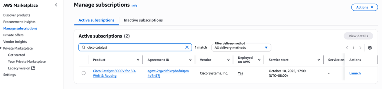
Figure 3: Accepting terms and conditions for Cisco Catalyst 8000V on AWS Marketplace.
4. Select Amazon EC2 in the Service option and choose Launch from EC2 Console as the launch method. Turn on Auto-assign public IP for both virtual router instances.
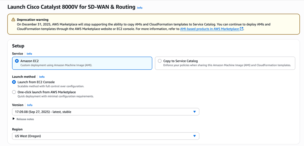
Figure 4: Launching Cisco Catalyst 8000V from EC2 Console with auto-assign public IP enabled.
5. Associate an IAM role with at least the AmazonSSMManagedInstanceCore policy to all non-Cisco EC2 instances. Cisco virtual router EC2 instances have a built-in IAM role attached already.
Configuration steps
Configure each component in the following order: VR-cloud, VR-onprem, the multicast sender and receiver, and finally the AWS Transit Gateway multicast domain.
Configuring VR-cloud
VR-cloud requires a LAN port ENI in addition to its default WAN port. You add this ENI from your local machine or a cloud-based bastion host using the AWS CLI, then log into VR-cloud directly to configure routing and multicast.
To add a LAN port ENI to VR-cloud
1. Verify that you have installed and configured the AWS CLI with API keys for this account (if running locally) or that your bastion host can reach VR-cloud (if running from the cloud).
2. Create a network interface in Subnet 4 (not Subnet 3) with the security group ID of VR-cloud. Run the following command.
sh
aws ec2 create-network-interface \
--subnet-id <subnet-id> \
--description "LAN port" \
--groups <security-group-id>
3. Extract the ENI ID (NetworkInterfaceId) from the JSON output. The following is an example of the expected output.
4. Attach the new ENI to VR-cloud. Replace the instance-id with the VR-cloud instance ID from the Amazon EC2 console.
sh
aws ec2 attach-network-interface \
--network-interface-id <eni-id> \
--instance-id <ec2-instance-id> \
--device-index 1
5. Disable SourceDestCheck on both the WAN port and LAN port ENIs of VR-cloud. Run the following two commands separately. (Explanation: By default, AWS enables Source/Destination Check on every ENI. This means AWS will drop packets where the ENI’s own private IP is neither the source IP nor the destination IP. This is a security feature to prevent spoofing — a normal EC2 instance should only send/receive traffic addressed to/from itself. However, EC2 instances acting as routers, NAT gateways, firewalls, or proxies — those that forward packets not addressed to/from themselves — must have SourceDestCheck disabled. VR-cloud is a multicast router bridging a GRE tunnel to a TGW multicast domain, so both its ingress (WAN) and egress (LAN) interfaces handle transit traffic with non-local IP addresses.)
sh
aws ec2 modify-network-interface-attribute --network-interface-id <WAN port ENI id> --no-source-dest-check
aws ec2 modify-network-interface-attribute --network-interface-id <LAN port ENI id> --no-source-dest-check
After adding the LAN port ENI, log into VR-cloud to configure the GRE tunnel, multicast routing, and OSPF.
To configure VR-cloud routing and multicast
1.Log into VR-cloud using SSH. Use the .pem key file and the appropriate IP address.
sh
ssh -I “<path-to-key.pem>” -o PubkeyAcceptedKeyTypes=+ssh-rsa \
ec2-user@<VR-cloud IP address>
For internet login, use the EC2 Public DNS (for example, ec2-xx-xx-xx-xx.us-east-1.compute.amazonaws.com). For internal network login, use the EC2 private Ipv4 address.
2. Enter configuration mode by running config t.
3. Configure the GRE tunnel on the WAN port. Replace A.B.C.D with the public IP address of VR-onprem.
4. Enable multicast routing.
5. Configure PIM sparse mode on the upstream port (the tunnel port connected to the multicast source).
6. Configure PIM sparse mode on the downstream port (the LAN port where multicast traffic is forwarded).
7. Configure a static IGMP join for the required multicast group on the LAN port. Transit Gateway does not support transparent transmission of IGMP join messages, so the virtual router cannot dynamically detect receivers. (Explanation: In a normal multicast network, downstream receivers send IGMP Join messages upstream so the router knows to forward traffic for that group. However, AWS Transit Gateway acts as an IGMP termination point — it accepts IGMP Joins from receivers in App VPC to manage its own replication table, but it does not relay those Joins upstream to VR-cloud’s LAN port. Without receiving an IGMP Join, VR-cloud assumes no one wants the multicast group and drops the traffic.The static IGMP join permanently tells VR-cloud “always forward group 232.0.0.1 out GigabitEthernet2,” bridging the signaling gap that TGW’s architecture creates.)
8. Specify the Rendezvous Point (RP) for PIM Sparse Mode. Set it to the local router’s GRE tunnel address. (Explanation: In PIM Sparse Mode, multicast traffic only flows where explicitly requested — the RP serves as the central meeting point where sources register their traffic and receivers send Joins to request it, enabling PIM to build the multicast distribution tree. Without an RP, PIM has no mechanism to connect sources to receivers, and no multicast traffic will flow at all. It is set to tunnel address (169.254.100.1) because that router sits closest to the CME multicast source, minimizing registration overhead. Both VR-cloud and VR-onprem can reach 169.254.100.1 via OSPF over the GRE tunnel (this is exactly why OSPF was enabled).)
The Explanation of using 169.254.x.x as tunnel address: The 169.254.x.x range is a link-local address space (RFC 3927) reserved for communication between directly connected devices on a point-to-point link, which is exactly what a GRE tunnel is. It’s ideal here because these addresses are non-routable and will not conflict with real VPC CIDRs (10.0.0.0/24, 10.1.0.0/24) or production networks, require no IP allocation planning, and align with AWS’s own convention of using 169.254.x.x for internal link-local services like instance metadata (169.254.169.254) and Transit Gateway VPN tunnel addresses.
9. Enable the OSPF routing protocol. (Explanation: PIM (Protocol Independent Multicast) does not maintain its own routing table — it relies on the unicast routing table to perform RPF (Reverse Path Forwarding) checks, which verify that incoming multicast packets arrived on the correct interface facing back toward the source. Without a unicast route to the multicast sender’s network through the GRE tunnel, every multicast packet arriving at VR-cloud would fail the RPF check and be silently dropped. OSPF on the 169.254.100.0/30 tunnel link provides exactly this: it gives VR-cloud a learned route back toward VR-onprem and the multicast source, so PIM can validate the forwarding path, reach the Rendezvous Point (169.254.100.1), and build the multicast distribution tree correctly.)
10. Type end to exit configuration mode. In privileged EXEC mode (#), enter write to save the configuration.
Configuring VR-onprem
Next, configure VR-onprem. The process is similar: add a LAN port ENI, then log in to configure routing and multicast.
To add a LAN port ENI to VR-onprem
1. Verify that you have installed and configured the AWS CLI with API keys for this account (if running locally) or that your bastion host can reach VR-onprem (if running from the cloud).
2. Create a network interface in Subnet 1 (not Subnet 2) with the security group ID of VR-onprem. Run the following command.
sh
aws ec2 create-network-interface \
--subnet-id <subnet-id> \
--description "LAN port" \
--groups <security-group-id>
3. Extract the ENI ID (NetworkInterfaceId) from the JSON output. The following is an example of the expected output.
4. Attach the new ENI to VR-onprem. Replace the instance-id with the VR-onprem instance ID from the Amazon EC2 console.
sh
aws ec2 attach-network-interface \
    --network-interface-id <eni-id> \
    --instance-id <ec2-intance-id>\
    --device-index 1
5. Disable SourceDestCheck on both the WAN port and LAN port ENIs of VR-onprem. Run the following two commands separately.
sh
aws ec2 modify-network-interface-attribute \
    --network-interface-id <WAN port ENI id> --no-source-dest-check

aws ec2 modify-network-interface-attribute \
    --network-interface-id <LAN port ENI id> --no-source-dest-check
After adding the LAN port ENI, log into VR-onprem to configure the GRE tunnels, multicast routing, and OSPF.
To configure VR-onprem routing and multicast
1. Log into VR-onprem using SSH. Use the .pem key file and the appropriate IP address.
sh
ssh -i "<path-to-key.pem>" -o PubkeyAcceptedKeyTypes=+ssh-rsa \
    ec2-user@<VR-onprem IP address>
For internet login, use the EC2 Public DNS (for example, ec2-xx-xx-xx-xx.us-east-1.compute.amazonaws.com). For internal network login, use the EC2 private IPv4 address.
2. Enter configuration mode by running config t.
3. Configure the GRE tunnel on the WAN port. Replace E.F.G.H with the public IP address of VR-cloud.
4. Configure the GRE tunnel on the LAN port. Replace the tunnel destination with the multicast sender’s private IP address.
5. Enable multicast routing.
6. Enable PIM sparse mode on both tunnel interfaces.
7. Specify the Rendezvous Point (RP).
8. Enable the OSPF routing protocol on both tunnel networks.
9. Type end to exit configuration mode. In privileged EXEC mode (#), enter write to save the configuration.
You’ve now configured both VR-cloud and VR-onprem.
Configuring multicast sender and multicast receiver
The multicast sender requires a GRE tunnel to VR-onprem because the walkthrough environment runs within an Amazon VPC, which does not natively support multicast. In a production environment, this portion runs in CME Group’s on-premises data center and is not subject to Amazon VPC limitations.
To configure the multicast sender
1. Disable SourceDestCheck on the WAN port ENI of both the multicast sender and multicast receiver. Run the following command for each ENI.
sh
aws ec2 modify-network-interface-attribute \
    --network-interface-id <WAN port ENI id> --no-source-dest-check
2. Log into the multicast sender.
3. Create a GRE tunnel between the multicast sender and VR-onprem. Run the following commands.
sh
sudo ip tunnel add gre1 mode gre \
    local <multicast sender private IP address> \
    remote <VR-onprem LAN IP address> ttl 255
sudo ip addr add 169.254.200.2/30 dev gre1
sudo ip link set gre1 up
sudo ip route add 224.0.0.0/4 dev gre1
Configuring Transit Gateway
The AWS Transit Gateway multicast domain distributes multicast traffic between the Transit VPC and the Application VPC. Create the Transit Gateway with multicast support enabled, then configure attachments and multicast group membership.
To create and configure the Transit Gateway multicast domain
1. Navigate to VPC > Transit gateways in the AWS Management Console and create a Transit Gateway. DNS Support, Security Group Referencing support, VPN ECMP support are toggled by default. You just need to toggle Multicast support to enable it.
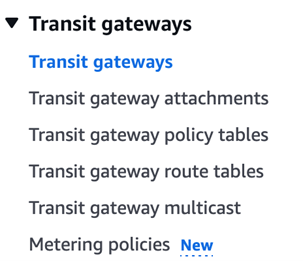
Figure 5: Creating a Transit Gateway in the AWS Management Console.
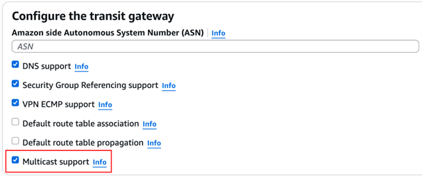
Figure 6: Transit Gateway multicast settings with Multicast support enabled.
2. Navigate to VPC > Transit gateway multicast and create a Transit Gateway multicast domain. Toggle Static sources support rather than Auto accept shared associations because this prototype uses static mode. IGMPv2 support is automatically disabled when toggling Static source support since IGMPv2 supports only dynamic membership management rather than static.
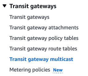
Figure 7: Creating a Transit Gateway multicast domain with static sources support enabled.
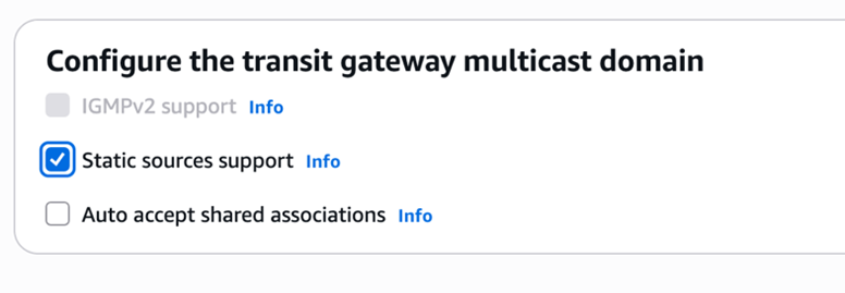
Figure 8: Transit Gateway multicast domain association settings.
3. Create two Transit Gateway VPC attachments. Keep the VPC attachment settings at their default values. (by default, DNS support and Security Group Referencing support are toggled, while Ipv6 support and Appliance Mode support are not.)
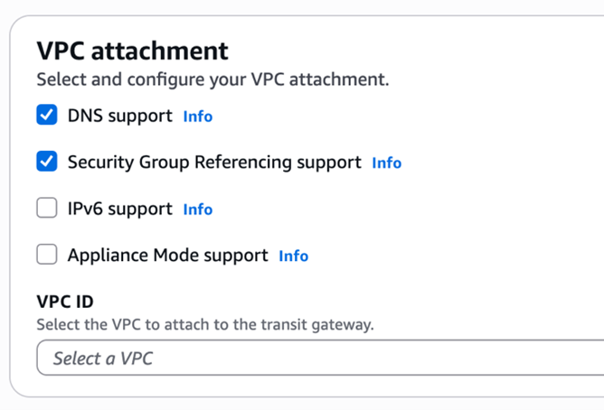
Figure 9: Creating a Transit Gateway VPC attachment.
Create the following attachments:
• Transit VPC Attachment: Associate with Subnet 4 in the Transit VPC.
• Application VPC Attachment: Associate with Subnet 5 in the Application VPC.
4. Associate both Transit Gateway attachments with the previously created Transit Gateway multicast domain.
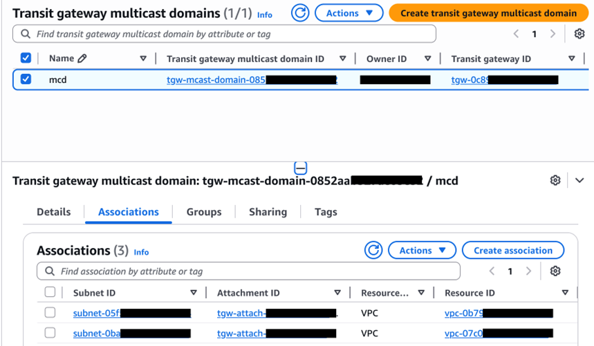
Figure 10: Associating Transit Gateway attachments with the multicast domain.
5. Register the multicast group source and member with the following parameters:
• Multicast Group Address: 232.0.0.1
• Multicast Source: VR-cloud’s LAN port ENI
• Multicast Member: Multicast receiver’s ENI
6. Register the multicast group source. Run the following command.
sh
aws ec2 register-transit-gateway-multicast-group-sources \
--transit-gateway-multicast-domain-id <tgw multicast domain id> \
--group-ip-address 232.0.0.1 \
--network-interface-ids <VR-cloud LAN port ENI id> \
--region us-east-1
7. Register the multicast group member. Run the following command.
sh
aws ec2 register-transit-gateway-multicast-group-members \
--transit-gateway-multicast-domain-id <tgw multicast domain id> \
--group-ip-address 232.0.0.1 \
--network-interface-ids <multicast receiver ENI id> \
--region us-east-1
Testing and validation
With all components deployed and configured, test the setup by running connectivity, throughput, and latency tests.
Connectivity verification
Verify that your multicast data flows end-to-end before running performance tests.
This connectivity test validates your end-to-end multicast data transmission across the complete path: multicast sender → VR-onprem → VR-cloud → TGW Multicast Domain → multicast receiver. Deploy multicast transmission and reception scripts on the sender and receiver instances respectively to verify this.
Test procedure
On the multicast receiver instance:
sh
git clone https://github.com/aws-samples/sample-cap-quant.git
cd sample-cap-quant/data-processing/CME Group-mdp-multicast-data-access/scripts/
python3 test-receiver.py
On the multicast sender instance:
sh
git clone https://github.com/aws-samples/sample-cap-quant.git
cd sample-cap-quant/data-processing/CME Group-mdp-multicast-data-access/scripts/
python3 test-sender.py
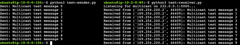
Figure 11: End-to-end multicast connectivity test results showing successful data transmission.
TGW multicast transfer mode test
TGW multicast transfer mode test objective
This test shows you how to measure TGW Multicast Domain bandwidth performance using Amazon CloudWatch.
Test scenario design
Based on customer engagements, three multicast distribution modes address different application scenarios. Mode 1 uses a single Application VPC with one multicast receiver, making it ideal for demo, prototyping, and testing purposes. Mode 2 places two multicast receivers in a single Application VPC, keeps your data highly available for production environments with a single downstream consumer.
Mode 3 distributes one multicast receiver across each of two App VPCs, supporting production environments with multiple downstream data consumers. You can implement additional high availability by adding another multicast receiver in each VPC.
- Mode 1: Single App VPC with 1 multicast receiver
- Mode 2: Single App VPC with 2 multicast receivers
- Mode 3: Two App VPCs, each hosting 1 multicast receiver
These scenarios validate TGW’s ability to efficiently distribute multicast traffic across different VPC topologies.
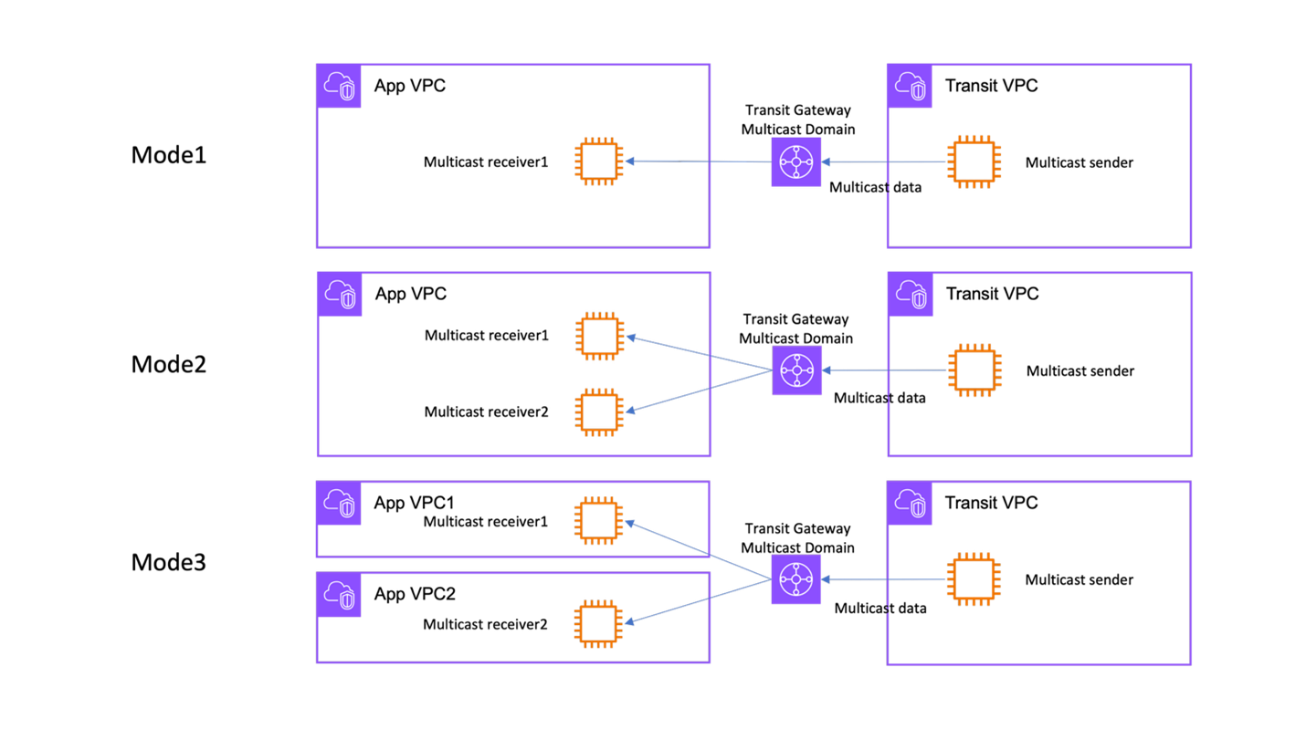
Figure 12: Three TGW multicast distribution modes: single receiver, dual receivers in one VPC, and receivers across two VPCs.
Test data specification
The throughput test simulates COMEX gold futures market data at 1,000 records per second. Each record follows the CME GROUP MDP data format:
TGW multicast transfer mode test procedure
On each multicast receiver instance:
sh
cd sample-cap-quant/data-processing/CME Group-mdp-multicast-data-access/scripts/
python3 1k-receiver.py
On the multicast sender instance:
sh
cd sample-cap-quant/data-processing/CME Group-mdp-multicast-data-access/scripts/
python3 1k-sender.py
Test duration and measurement methodology
Each test scenario executed for 60 seconds at a sustained rate of 1,000 records per second. Amazon CloudWatch captured the throughput metrics, specifically monitoring TGW BytesOut and BytesIn metrics to measure data transmission volumes across the multicast domain.
Performance test results
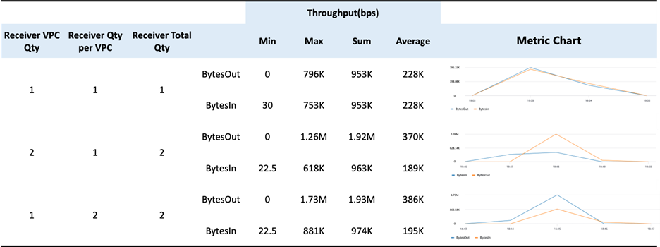
Figure 13: TGW multicast throughput performance results across three distribution modes.
*Please note that the test was done and the above data was collected in us-east-1 region.
Throughput and scalability findings
TGW Multicast Efficiency: The results demonstrate TGW’s ability to efficiently implement cloud-native multicast distribution. Adding receivers requires minimal configuration: simply registering new members in the TGW Multicast Domain. This confirms that Transit Gateway delivers the fundamental advantages of multicast technology (one-to-many distribution) within the AWS cloud environment, significantly reducing operational complexity compared to traditional unicast replication approaches.
Scalability Characteristics: The throughput scaling from Mode 1 (228K bps) to Mode 2 (370K bps) and Mode 3 (386K bps) demonstrates near-linear scaling as additional receivers join the multicast group. These throughput levels support typical CME Group MDP market data feeds for instruments like COMEX gold futures. This confirms TGW’s replicates packets without overhead mechanism.
TGW latency test
TGW latency test objective
This test shows you how to measure latency of the TGW Multicast Domain.
TGW latency test procedure
On the multicast receiver instance:
sh
cd sample-cap-quant/data-processing/CME Group-mdp-multicast-data-access/scripts/
python3 latency -receiver.py
On the multicast sender instance:
sh
cd sample-cap-quant/data-processing/CME Group-mdp-multicast-data-access/scripts/
python3 latency-sender.py
End-to-End Latency Results
This test deployed the receiver and VR-cloud in the same Availability Zone to minimize inter-AZ latency.
Breaking down the latency measurement
To isolate TGW’s latency contribution, the test used ICMP ping measurements across different path segments:
Test Path Definitions
- Path #1: Sender → VR-onprem (through GRE tunnel)
- Path #2: VR-onprem → VR-cloud (cross-AZ)
- Path #3: Sender → VR-cloud (combined path)
TGW Multicast Domain Latency Calculation
Isolated TGW latency:
VR-cloud → TGW Multicast Domain → Receiver = E2E latency – Sender to VR-cloud latency
Conclusion
In this post, you deployed Cisco Catalyst 8000V routers, configured GRE tunnels with PIM, established Transit Gateway multicast domains, and validated performance with throughput and latency tests. Performance testing confirms that AWS Transit Gateway multicast domains deliver efficient packet replication with near-linear throughput scaling across multiple receivers.
Next steps
Scale to production: Replace the simulated on-premises environment with AWS Direct Connect to CME Group’s data center for production-grade latency and reliability. Before deploying, verify that your AWS Direct Connect link supports the required bandwidth for your market data feeds and monitor round-trip latency to confirm it meets your trading appplication requirements. You can contact AWS Support, Solutions Architects, or Professional Services for assistance with production deployments.
Add high availability: Deploy additional multicast receivers in each Amazon VPC to provide data redundancy. Monitor packet loss rates using Amazon CloudWatch to validate failover behavior.
Integrate with downstream applications: Connect the multicast receivers to analytics pipelines, order management applications, or risk engines for real-time market data processing.
Adapt for other data sources: This architecture works with other multicast data providers beyond CME Group MDP.
Explore these resources to learn more about the services and tools in this solution:
- AWS Transit Gateway multicast configuration guide
- Amazon VPC configuration guide
- AWS Direct Connect setup reference
- Amazon CloudWatch metrics and monitoring for network performance
- Amazon EC2 deployment guide
- CME Group Market Data Platform connectivity
- Cisco Catalyst 8000V virtual router marketplace entrance on AWS
The sample scripts used in this walkthrough are available in the sample-cap-quant GitHub repository