AWS for Industries
IPv6 smart meter migration to AWS: A NAT proxy solution for AMISPs
Power distribution utilities worldwide are accelerating their digital transformation by migrating advanced metering infrastructure (AMI) systems to the cloud. This migration provides utilities a way to leverage the scalability, resiliency, cost efficiency, and enhanced analytics capabilities of Amazon Web Services (AWS).
Smart metering market trends and growth drivers
The smart metering landscape is experiencing unprecedented growth driven by regulatory mandates and technological innovation. AMI deployment is rapidly expanding as utilities seek comprehensive solutions that enable real-time data collection, remote monitoring, and enhanced communication between utilities and consumers.
Current market indicators show robust expansion:
- According to industry forecasts, the global utility scale smart meter market is positioned for substantial growth. The market is projected to surpass USD 15.7 billion by 2032, representing a robust compound annual growth rate (CAGR) of 16.3%
- Smart meter shipments are expected to grow from 173.29 million units in 2025 to 257.62 million units by 2030.
- The global AMI meters market was valued at USD 28.8 billion in 2024 and is estimated to grow at a CAGR of 13.1% through 2034.
- Utilities are accelerating capital spending as regulators increasingly define smart metering as critical infrastructure. This regulatory shift recognizes the cybersecurity risks posed by nation-state actors who could adversely affect large portions of the power grid through compromised AMI systems.
- Energy demand continues to intensify with the proliferation of energy-intensive workloads, such as generative AI data centers and EV charging. In response, AMI solutions provide utilities with granular control and real-time monitoring capabilities essential for managing large numbers of residential and commercial loads.
This market momentum creates both opportunities and challenges for utilities seeking to modernize their infrastructure, while maintaining operational continuity.
The problem
Some utilities deployed smart meters using IPv6 addresses from the fc00::/8 range during early AMI implementations. This choice now creates compatibility challenges when migrating to cloud platforms, as RFC 4193 designates the fc00::/8 block as undefined and reserved. To ensure compliance with RFC standards, Amazon Virtual Private Cloud (Amazon VPC) IP Address Manager (IPAM) reserves this IP range, aligning with industry best practices. Given that millions of smart meters are already deployed across utility service territories, updating IPv6 addresses before cloud migration presents significant operational and cost challenges, making field reconfiguration impractical.
AWS enables utilities to successfully use undefined and reserved IPv6 address schema (fc00::/8) while maintaining RFC standards.
Non-compliant IPv6 addressing in smart meter deployments
AWS Energy specialists have observed that many advanced metering infrastructure service providers (AMISP) manage large fleets of smart meters, which communicate with head-end systems (HESs) using IPv6 addresses from the fc00::/8 range. It has been observed that during early AMI implementations, smart meter manufacturers and system integrators often configured these addresses without strict adherence to RFC 4193 standards. RFC 4193 designates the fc00::/8 block as undefined and reserved for future use.
This non-compliant approach creates migration challenges when utilities attempt to move to cloud platforms that enforce strict RFC standards compliance. It prevents field-deployed smart meters from maintaining communication with HESs already migrated to AWS. This incompatibility risks disrupting essential metering operations and data collection that utilities rely on for billing, grid management, and customer service.
Operational constraints
Updating meter IPs in the field before migration presents several operational challenges:
- Field visits to millions of deployed meters would be prohibitively expensive
- Service interruptions during IP reconfiguration could impact billing and operations
- The time required for a complete field update could delay cloud migration
- Coordination complexity across multiple geographic regions adds further complications
We will demonstrate how utilities can overcome these challenges using a NAT64 proxy solution with any enterprise firewall that supports NAT64 translation capabilities, enabling seamless cloud migration without field disruption. While this implementation showcases FortiGate (Fortinet Firewalls) as the firewall solution, the architectural pattern can be applied with any NAT64-capable firewall appliance.
Solution overview
Network address translation bridge for field-deployed IPv6 smart meter integration
AWS-native services and proven firewall technology create a network address translation bridge that enables seamless communication between field-deployed smart meters and AWS infrastructure. This solution implements NAT64 translation to convert IPv6 smart meter traffic to IPv4 application endpoints when the HESs applications use an IPv4 stack. For utilities with IPv6-compatible HESs applications, NAT66 translation serves as an alternative approach for IPv6-to-IPv6 address translation. This transparent translation layer maintains operational continuity, while enabling cloud migration.
Architecture components
AWS enables usage of reserved and undefined IPv6 addresses through an innovative solution that leverages NAT64 capabilities in Firewalls to translate these addresses into IPv4. Following are the various components and AWS services used in the solution architecture:
- Core infrastructure elements
- Firewall VPC: Serves as the critical translation layer, hosting the NAT64-capable firewall appliance that enables communication between legacy IPv6 smart meters and AWS-compliant applications.
- Application VPC: Hosts the migrated smart meter applications and backend systems, serving as the primary environment for HESs and related utility applications.
- AWS Transit Gateway: Functions as the central networking hub, providing scalable, resilient and high-performance routing between VPCs and external connections to meet utility networking requirements.
- NAT-capable firewall: Acts as the translation proxy, performing bidirectional address translation between IPv6 and IPv4 protocols (FortiGate is demonstrated in this implementation).
- Network connectivity layer
- AWS Direct Connect: Provides dedicated, private connectivity between the utility’s multiprotocol label switching (MPLS) network and AWS infrastructure, verifying reliable and secure data transmission for mission-critical utility communications.
- MPLS network: Provides the backbone connectivity that securely transports data from geographically distributed smart meters to AWS over Direct Connect, facilitating performance, reliability and private reachability.
- Smart meters: Edge devices in the advanced metering infrastructure systems, deployed across utility service territories with existing fc00::/8 IPv6 addressing schemes.
- AWS services integration
- Amazon Elastic Compute Cloud (Amazon EC2): Provides the compute infrastructure for deploying the FortiGate firewall instances with appropriate performance and scalability characteristics.
- AWS Transit Gateway: Routes IPv6 overlay IP addresses that reside within the firewall appliance rather than directly on the network interfaces, enabling the NAT64 translation process to operate effectively in the AWS environment.
- AWS Direct Connect: Provides reliable, high-bandwidth connectivity with predictable network performance.
- Amazon VPC IPAM: Manages private IPv6 ULA space fd00::/8 (except fd00::/16), providing centralized address space management, while maintaining RFC standards compliance.
Traffic flow architecture
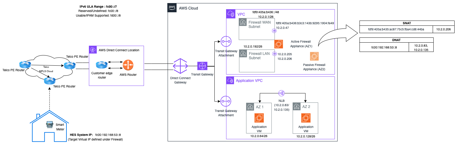
Figure 1. High-level solution architecture
The solution implements a seven-step bidirectional communication flow:
1. Smart meter initiation: Smart meters with fc00::/8 range IPv6 address send traffic to the utility’s MPLS network, connected to AWS through Direct Connect.
2. AWS ingress: Direct Connect forwards traffic to AWS Transit Gateway, serving as the central routing hub.
3. Route distribution: Transit Gateway routes traffic with a destination IP address from fc00::/8 range to the Firewall VPC based on a route table configuration.
4. Firewall engagement: The Firewall VPC route table directs traffic to the primary ENI of the NAT64-capable firewall.
5. NAT64 translation process: The FortiGate firewall performs dual translation:
a. DNAT (destination NAT): Translates the destination IPv6 address to the IPv4 address of the target application.
b. SNAT (source NAT): Translates the source IPv6 address to the IPv4 address of the secondary ENI.
6. Application delivery: Translated IPv4 traffic exits through the secondary ENI (Port2) and routes to the Network Load Balancer or application server.
7. Return path processing: Response traffic follows the reverse path with automatic IPv4-to-IPv6 translation, verifying transparent bidirectional communication.
This solution architecture directly solves the core problem by creating a translation bridge that allows existing smart meters to communicate with AWS-hosted HESs without requiring field equipment changes or IPv6 address reconfiguration.
Step-by-step solution configuration
This section provides a comprehensive operational framework for implementing the AWS NAT64 proxy solution architecture for migrating field-deployed AMI smart meters. The solution provides utilities a way to leverage cloud benefits with zero field re-provisioning and operational disruption. While this solution demonstrates the implementation using FortiGate as the firewall solution, the same architectural principles apply to any enterprise firewall with NAT64 translation capabilities.
Firewall selection criteria
When selecting a firewall for this solution, confirm the appliance supports:
- RFC 6146-compliant NAT64 translation
- Dual network interface configuration
- IPv6 and IPv4 routing capabilities
- Stateful connection tracking
- Policy-based traffic management
- Comprehensive logging and monitoring
Popular enterprise firewalls that support these capabilities include FortiGate, Cisco, Palo Alto Networks, Check Point Software Technologies Ltd., and others. This solution demonstrates FortiGate configuration as a reference example.
AWS setup
The AWS infrastructure setup provides the foundational networking layer so utilities can migrate their AMI systems, while maintaining connectivity with field-deployed smart meters using legacy IPv6 addressing. This setup creates the necessary cloud environment before implementing the critical FortiGate NAT64 translation layer.
Infrastructure preparation
The solution leverages two VPCs, each configured with IPv6 CIDR allocations from the Amazon VPC IPAM IPv6 pool (fd00::/8), to establish the foundation for your network architecture. Essential VPC endpoints facilitate secure service communication, while AWS Transit Gateway provides the central routing hub connecting both VPCs and external networks. AWS Direct Connect integration establishes the dedicated pathway between your existing MPLS network and the AWS cloud environment.
Routing foundation
Transit Gateway route tables are configured to handle standard inter-VPC communication. It adds the critical routing rule that directs legacy fc00::/8 traffic from field smart meters to the Firewall VPC. This routing configuration creates a traffic flow pathway that enables the NAT64 translation process without disrupting existing meter communications.
Operational readiness
Once the AWS networking foundation is established, the environment is ready to support the FortiGate firewall deployment that performs the actual IPv6-to-IPv4 translation. This AWS setup serves as the stable foundation upon which the NAT64 solution operates, providing the scalability and reliability utilities needed for critical metering infrastructure.
The AWS environment setup is intentionally straightforward, leveraging standard AWS networking services to create a robust foundation. The technical complexity and innovation of this solution is the FortiGate firewall configuration, which we’ll explore in detail in the following section.
FortiGate firewall server configuration
The FortiGate firewall serves as the critical translation engine in this architecture. It provides RFC 6146-compliant NAT64 translation that enables seamless communication between legacy IPv6 smart meters and AWS-hosted IPv4 applications.
Performance and scalability considerations
When implementing the NAT64 solution, utilities must size firewall instances for peak traffic loads rather than average operational demands. Smart meter networks experience significant traffic spikes during recovery scenarios, such as when cellular or radio systems recover from extended outages. This can cause thousands of meters to simultaneously synchronize accumulated data. Additionally, distribution network service provider (DNSP) diagnostic operations may require meters to transmit at five-second intervals for extended periods, multiplying normal traffic volumes.
Deploy FortiGate instances in an Active/Passive configuration across different Availability Zones with automated heartbeat monitoring and vendor-provided failover scripts that automatically update route tables without manual intervention. Also, account for NAT64 translation overhead in performance calculations and verify adequate bandwidth provisioning through both AWS Direct Connect and Transit Gateway to handle traffic spikes without service degradation.
Instance and network interface setup
Deploy the FortiGate instance in your Firewall VPC’s public subnet with a crucial dual-ENI configuration. The primary ENI (Port1) receives incoming traffic from smart meters, while a secondary ENI with dual private IP addresses handles outgoing translated traffic.
Disable the source and destination checks on both ENIs through the AWS Management Console—this step is critical for proper traffic flow.
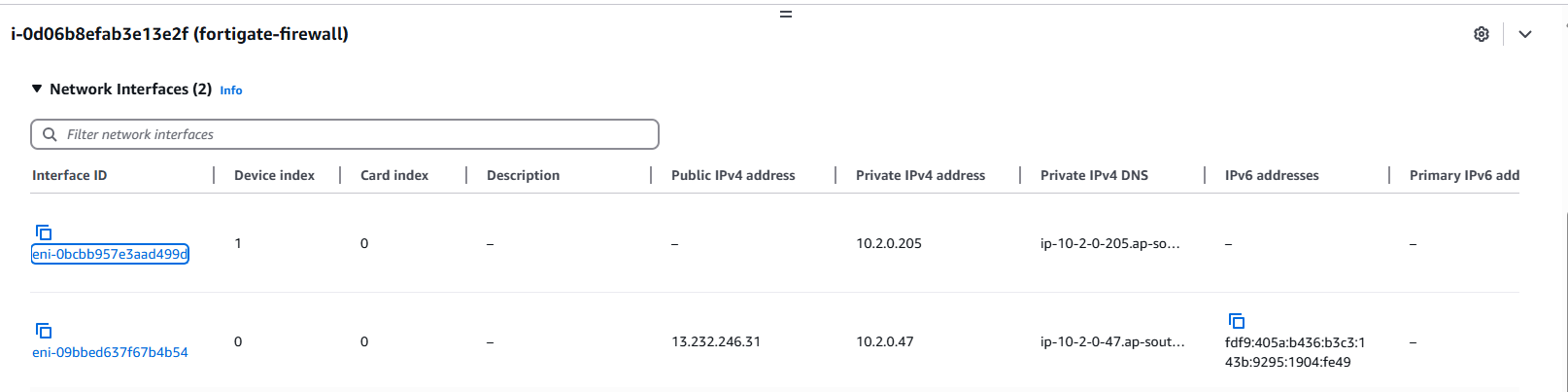
Figure 2: Firewall appliance interfaces
Configure the secondary ENI with both primary and secondary private IP addresses. The secondary IP becomes your NAT64 egress point, requiring an IP pool configuration that maps to this specific address for outbound traffic translation.
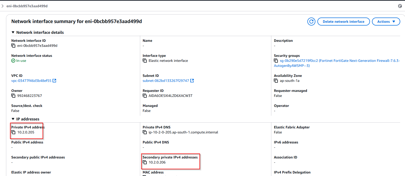
Figure 3: Firewall appliance secondary interfaces
Interface configuration and IPv6 enablement
Configure both FortiGate ports to establish the dual-interface architecture required for NAT64 translation. Port1 connects to the primary ENI for traffic ingress, while Port2 connects to the secondary ENI for translated traffic egress.
- Port1 configuration
Configure Port1 for automatic IPv6 addressing by selecting DHCP under the IPv6 Addressing model. This enables the FortiGate firewall to automatically obtain its IPv6 address from the VPC subnet configuration.
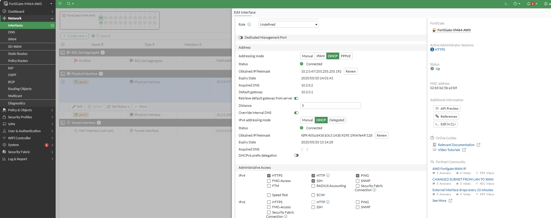
Figure 4: Port1 configuration
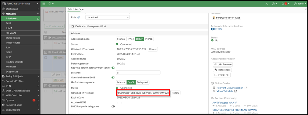
Figure 5: IPv6 Auto-configuration
- Port2 configuration
Port2 serves as the egress interface in the NAT64 architecture. Maintain the Port2 default manual addressing mode since this interface handles IPv4 communication for translated traffic routing to AWS applications.
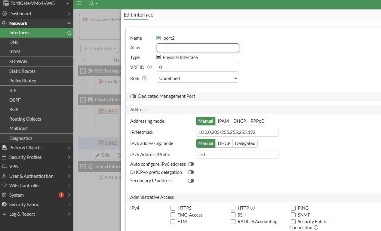
Figure 6: Default Port2 configuration
Route configuration requirements
Configure dual routing paths to establish proper traffic flow through the FortiGate firewall interfaces. Create two essential routes that define the ingress and egress traffic paths for the NAT64 translation:
- Ingress route (Port1): Directs incoming traffic from field-deployed smart meters (fc00::/8 source addresses through MPLS and Direct Connect) to the primary ENI’s IP address, confirming traffic enters the firewall through Port1 for initial processing.
- Egress route (Port2): Routes translated IPv4 traffic from the firewall to AWS applications through the secondary ENI, enabling proper delivery to Network Load Balancers or application servers.
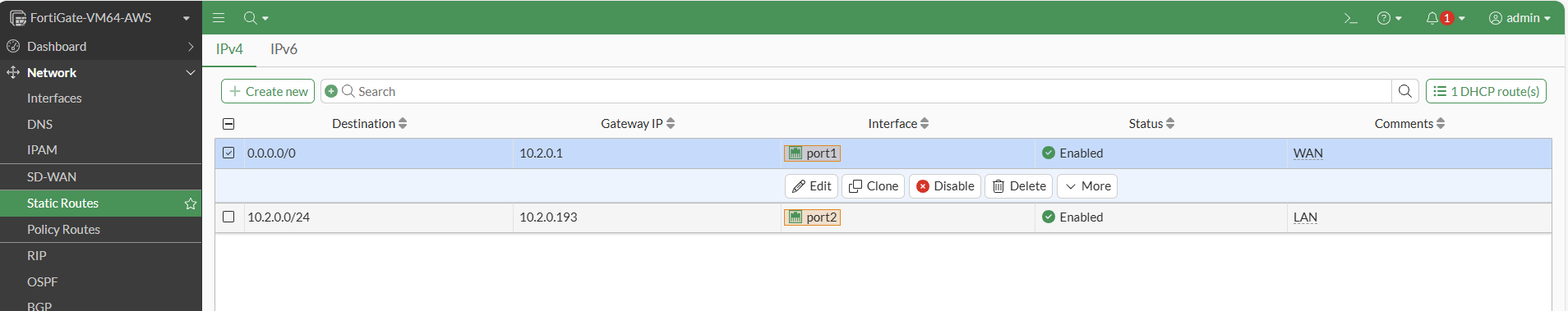
Figure 7: Dual route configuration
IP pool configuration
Configure an IP pool using the secondary IP address assigned to the secondary ENI for NAT64 egress traffic of the FortiGate firewall. The IP pool is essential for SNAT operations, enabling the firewall to translate IPv6 source addresses from smart meters into a consistent IPv4 address that AWS applications can route back through the return path.
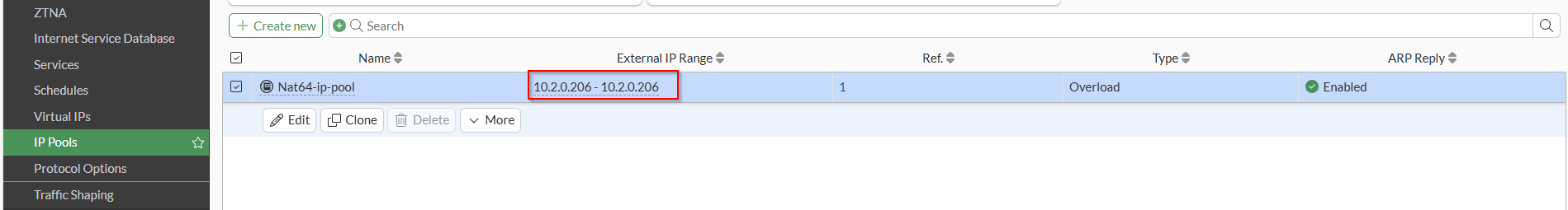
Figure 8: IP pool configuration
Virtual IP configuration
Configure the destination IP address for traffic routing. In this implementation, specify the Network Load Balancer IP address that will receive the translated IPv4 traffic from smart meters. Virtual IP configuration is essential for creating mapping between the incoming IPv6 traffic and the specific IPv4 destination services.
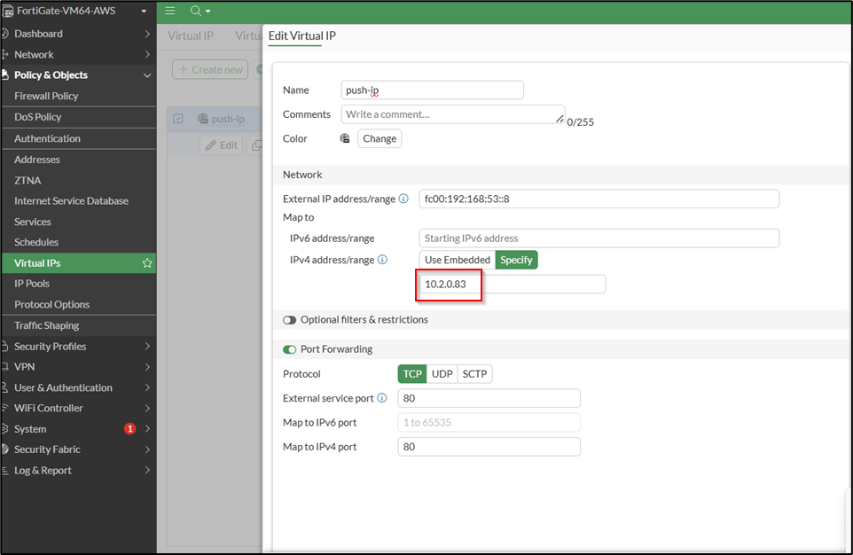
Figure 9: Virtual IP configuration
NAT64 policy implementation
The NAT64 policy configuration represents the core functionality of the FortiGate firewall, enabling bidirectional address translation between IPv6 smart meters and IPv4 AWS applications. This policy orchestrates the complete translation process that makes seamless communication possible.
- Firewall policy configuration
Create a comprehensive IPv6-NAT64 firewall policy with the following specifications:- Traffic direction: Configure the policy to accept incoming traffic from Port1 and route outgoing traffic to Port2.
- Source configuration: Set source as IPv6 ALL to accommodate traffic from any field-deployed smart meter using legacy IPv6 addressing.
- Destination mapping: Configure destination as the Virtual IP that maps to your AWS application endpoints (such as the Network Load Balancer IP).
- Service selection: Set service to ALL to confirm comprehensive protocol support for various smart meter communication requirements.
- NAT64 translation activation
Enable the critical NAT64 functionality within the firewall policy:- NAT64 option: Select NAT64 in the firewall options to activate the translation engine.
- IP pool reference: Choose the previously created NAT64 IP pool (configured with the secondary ENI’s IP address, such as 10.2.0.206) to handle source address translation.
- Dual translation process
The configured policy performs two essential translation operations:- Destination NAT translation:
- Converts incoming IPv6 destination addresses to the Virtual IP-mapped IPv4 addresses of the AWS applications.
- Verifies smart meter requests reach the correct HESs or meter data management systems (MDMSs) through the configured Virtual IP mapping.
- Maintains proper routing to Network Load Balancers or direct application servers.
- Source NAT translation:
- Translates IPv6 source addresses from smart meters to the IP pool address (secondary ENI’s IPv4 address).
- Creates a consistent return path that AWS networking can properly route back to the originating smart meters.
- Enables stateful connection tracking for bidirectional communication.
- Destination NAT translation:
- Policy validation and impact
This NAT64 policy configuration serves as the translation engine that enables the entire migration solution:- Protocol bridge: Creates the essential communication bridge between IPv6 smart meters and IPv4 AWS applications.
- Traffic orchestration: Coordinates complex address translations, while preserving application-layer protocols.
- Operational continuity: Enables immediate cloud migration without requiring field equipment modifications.
The policy effectively transforms incompatible IPv6 traffic into AWS-compatible IPv4 communications, so utilities can leverage cloud capabilities while maintaining their existing smart meter investments.
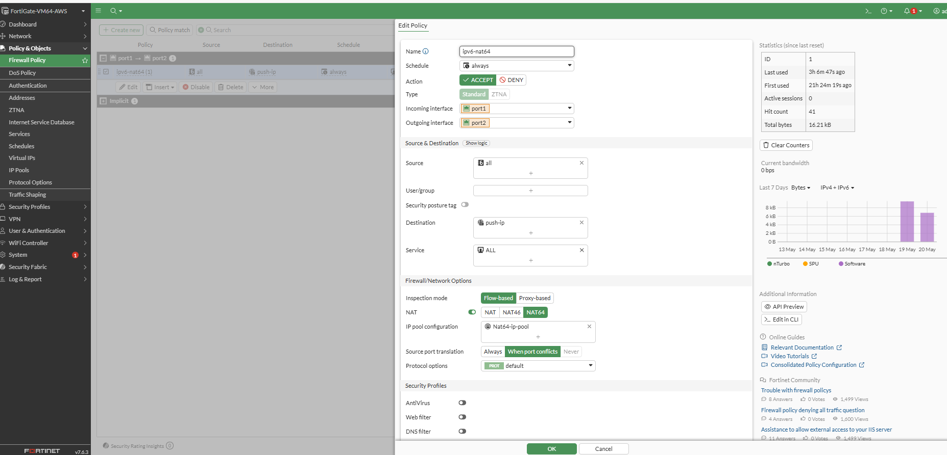
Figure 10: FortiGate IPv6-NAT64 policy configuration
Operational management and troubleshooting
FortiGate provides comprehensive monitoring capabilities essential for production deployments, such as:
- Packet capture: Built-in packet capture for NAT64 traffic analysis
- Debug logging: Detailed debug information for translation processes
- Flow monitoring: Traffic flow analysis across IPv6 and IPv4 domains
- Health monitoring: System health checks for NAT64 functionality
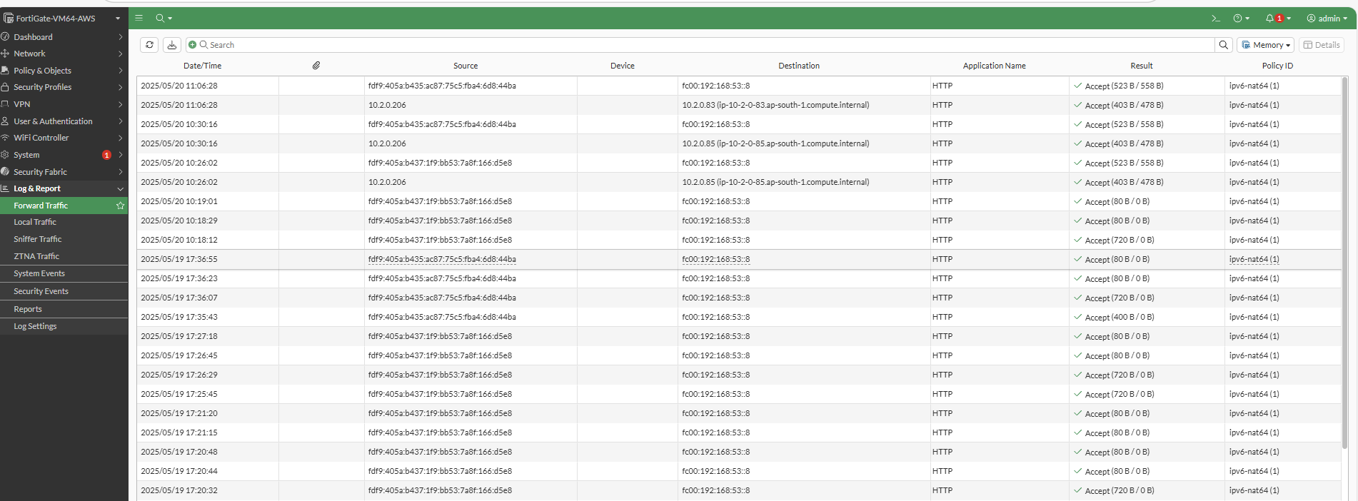
Figure 11: FortiGate forward traffic logs
The firewall’s policy logs provide real-time visibility into NAT64 translation events, enabling rapid troubleshooting and performance optimization. This monitoring capability is crucial for maintaining service levels during the migration period and beyond.
This configuration approach eliminates the need for field equipment changes, while providing a scalable, monitored solution that utilities can deploy across their entire AMI infrastructure. The FortiGate firewall effectively bridges the gap between legacy IPv6 deployments and AWS-compliant infrastructure. It enables immediate cloud migration benefits without operational disruption.
Benefits and limitations
This NAT64 proxy solution provides utilities with a strategic approach to cloud migration that balances immediate operational needs with long-term infrastructure goals.
Benefits
The solution addresses key migration challenges through these operational advantages:
- Zero field visits: Facilitates migration without requiring field visits to update meter IP addresses
- Operational continuity: Maintains uninterrupted service during migration
- Phased migration: Allows gradual transition to AWS-compliant services
- Cost efficiency: Eliminates the need for expensive field operations to update meter configurations
- Reusable pattern: Solution can be applied to any utility with legacy IPv6 deployments
Limitations
While this approach solves immediate migration challenges, utilities should be aware of these implementation considerations:
- Additional infrastructure: Requires maintaining the NAT64 proxy layer
- Translation overhead: Small performance impact from address translation
- Long-term planning: Eventually, utilities should consider updating field device addressing to comply with RFC 4193
Conclusion
We demonstrated how utilities can overcome IPv6 addressing challenges using a NAT64 proxy solution with any enterprise firewall that supports NAT64 translation capabilities. It enables seamless cloud migration without field disruption. While this implementation showcases FortiGate as the firewall solution, the architectural pattern can be applied with any NAT64-capable firewall appliance.
As the global smart meter market continues its rapid growth utilities need solutions that provide them ways to leverage cloud capabilities without disrupting their existing meter deployments. With our architectural solution approach utilities can accelerate their cloud migration journey, while maintaining operational continuity and minimizing field disruption.
Contact an AWS Representative for more information about how we can help accelerate your business.