Networking & Content Delivery
Choosing the right inspection architecture for AWS Network Firewall
Networking teams operating multi-VPC, multi-account environments need a consistent inspection architecture for compliance, threat detection, and traffic filtering. With the three deployment patterns now available for AWS Network Firewall (Traditional Inspection Amazon Virtual Private Cloud (Amazon VPC), Multiple VPC Endpoints launched May 2025, and Transit Gateway Native Attachment launched July 2025), a common question emerges: which pattern should I use? Each offers different trade-offs in complexity, cost, and scalability. This post provides a practical comparison with architecture diagrams, cost analysis, and a decision framework to help you choose the right inspection architecture for your environment
In 2020, we published Deployment models for AWS Network Firewall, which introduced the Inspection VPC pattern using AWS Transit Gateway. That architecture pattern with routing all traffic through a dedicated VPC containing firewall endpoints works well and remains supported, though it requires managing additional VPCs, subnets, route tables, and NAT Gateways. With the launches of Multiple VPC Endpoints and Transit Gateway Native Attachment, you now have alternatives that reduce this operational overhead while maintaining the same security posture.
This post walks you through all three patterns, explains how traffic flows in each architecture pattern, compares their costs, and provides a decision framework so you can make an informed choice without trial and error.
Quick comparison
Before examining each pattern in detail, the following table summarizes the key differences:
| Dimension | Traditional Inspection VPC | Multiple VPC Endpoints | Transit Gateway Native Attachment |
| E-W Inspection | Supported with Transit Gateway/AWS Cloud WAN | Not applicable | Supported with Transit Gateway (AWS Cloud WAN not supported) |
| N-S Inspection | Full | Full | Full |
| TLS Inspection | Supported | Not supported | Supported |
| Source IP Visibility | Preserved via Transit Gateway/AWS Cloud WAN | Preserved (local) | Preserved via Transit Gateway |
| Multi-Account | Transit Gateway/AWS Cloud WAN sharing + AWS Resource Access Manager (RAM) | Firewall sharing (AWS RAM) | Transit Gateway sharing + AWS RAM |
| Scope (data plane) | Large (Centralized) | Small (Distributed) | Large (Centralized) |
Table 1: Quick comparison between multiple Network Firewall deployment patterns
Pattern 1: Traditional Inspection VPC
In the traditional Inspection VPC pattern, you create a dedicated VPC containing Network Firewall endpoints. All east-west and north-south traffic routes through Transit Gateway (or AWS Cloud WAN core network) to that inspection VPC, where the firewall evaluates it before forwarding to the destination, as depicted in Figure 1
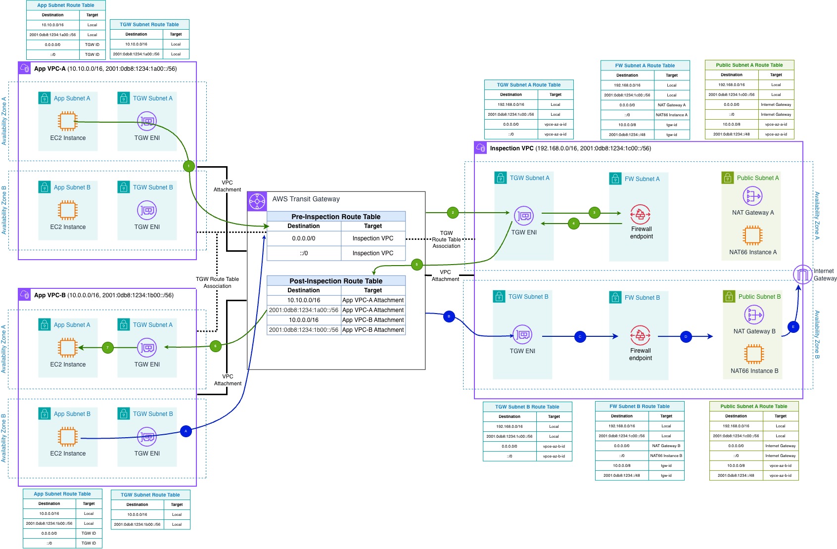
Figure 1: Inspection VPC architecture — VPC A and VPC B route traffic through AWS Transit Gateway to a dedicated Inspection VPC containing AWS Network Firewall.
Note: The route tables shown in all the architecture diagrams include both IPv4 and IPv6 routes. The traffic flow steps describe the IPv4 path; IPv6 follows the same sequence unless otherwise noted.
For IPv6 egress, a NAT66 instance performs IPv6-to-IPv6 source address translation before traffic exits through the Internet Gateway. NAT Gateway currently does not support NAT66.
East-west traffic flow
- Traffic from an instance in Workload VPC-A destined to Workload VPC-B is routed to the Transit Gateway, as per the Workload VPC-A route table (0.0.0.0/0 → tgw-id).
- The Transit Gateway pre-inspection route table (associated with the VPC attachments) forwards the traffic to the Inspection VPC attachment.
- In the Inspection VPC, the TGW subnet route table forwards the traffic to the firewall endpoint in the FW subnet.
- AWS Network Firewall inspects the traffic against the firewall policy. Allowed traffic is forwarded back to the Transit Gateway ENI in the TGW subnet.
- The Transit Gateway post-inspection route table (associated with the Inspection VPC attachment) forwards the traffic to Workload VPC-B’s attachment.
- In Workload VPC-B, the TGW subnet route table routes the traffic to the destination instance in the App subnet.
- Return traffic from VPC-B follows the same path in reverse (steps 1–6 in the opposite direction). Enable Transit Gateway appliance mode on the Inspection VPC attachment to maintain flow symmetry for east-west traffic.
North-South traffic flow
- Traffic from an instance in Workload VPC-B destined to the internet is routed to the Transit Gateway, as per the Workload VPC-B route table (0.0.0.0/0 → tgw-id).
- The Transit Gateway route table associated with the VPC attachment sends all the traffic (0.0.0.0/0) to the Inspection VPC.
- The Inspection VPC TGW subnet route table sends all the traffic to the firewall endpoint, where it is transparently inspected.
- Allowed traffic is sent to the NAT Gateway as per the Firewall subnet route table (0.0.0.0/0 → nat-id). The private IP of the source instance is translated to the private IP of the NAT Gateway, and in turn, translated to the public IP by the Internet Gateway.
- Traffic is sent out to the internet. Response traffic arrives at the Internet Gateway → NAT Gateway (stateful connection tracking) → firewall endpoint (stateful match) → Transit Gateway ENI → route table associated with the Inspection VPC forwards traffic to Workload VPC-B.
This pattern remains the right choice when your architecture requires granular control over routing within a dedicated Inspection VPC. For example, when you may need to apply different firewall policies based on traffic direction, or direct north-south and east-west traffic through separate paths. It is also appropriate when you have existing Transit Gateway infrastructure with established operational runbooks and team expertise built around this model.
Pattern 2: Multiple VPC endpoints
Launched in May 2025, this pattern takes a fundamentally different approach. Rather than funneling all traffic through a central Inspection VPC, you deploy secondary firewall endpoints directly into your spoke VPCs using VPC endpoint associations. This is a hybrid approach that gives you the best of both worlds: centralized cost, management, and policy logic with distributed performance, data paths, and network boundaries.
How this differs from distributed firewalls: In the distributed model, each VPC has its own independent firewall with a separate policy. Multiple VPC Endpoints takes a different approach. A single firewall extends secondary endpoints into spoke VPCs, sharing one centralized policy. This reduces cost (secondary endpoints are priced lower than primary endpoints) and eliminates policy drift.
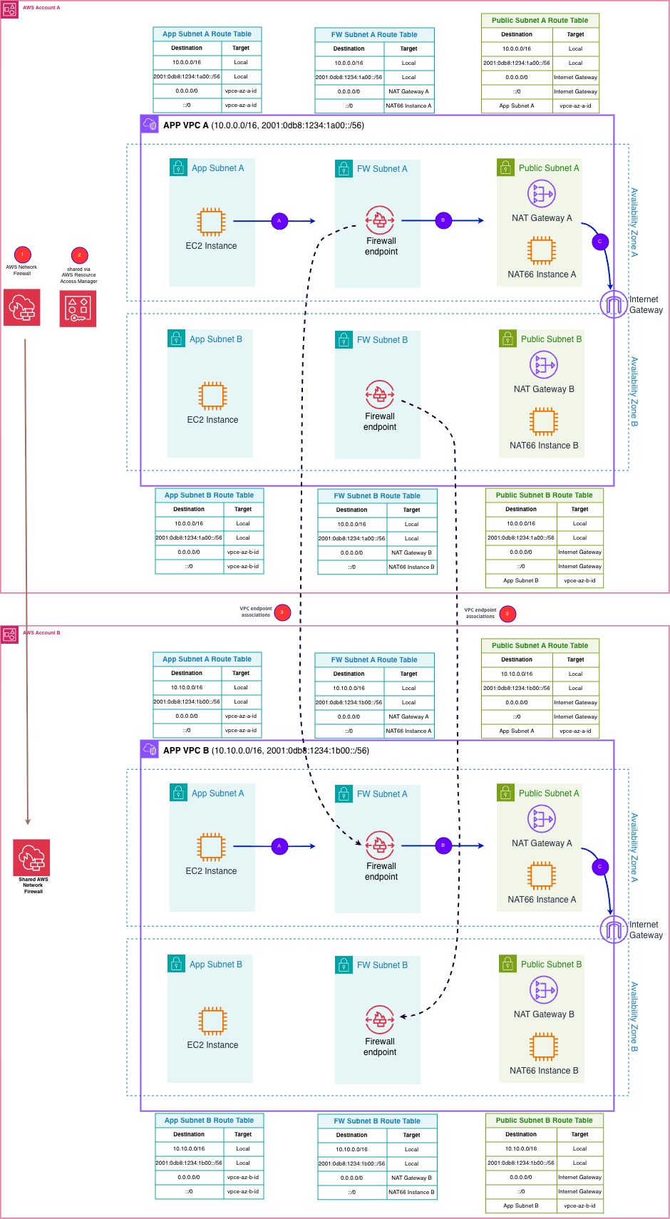
Figure 2: Multiple VPC Endpoints architecture — a primary firewall shares policy to secondary endpoints in spoke VPCs for local north-south inspection.
As shown in Figure 2, the architecture consists of AWS network firewall with a primary endpoint in VPC-A of Account A and secondary VPC endpoint associations deployed in VPC-B of Account-B. Cross-account support is available through AWS RAM for sharing firewall policies across accounts. The following steps enable the multi firewall endpoints across the accounts:
- Account A creates an AWS Network Firewall in VPC-A and assign the firewall policy
- Account A shares the firewall with Account B using AWS RAM. This allows Account B to create secondary endpoints associated with Account A primary firewall endpoint.
- Account B creates a VPC endpoint association in VPC-B, deploying a secondary firewall endpoint in the local FW subnet. This secondary endpoint enforces the same firewall policy defined in Account A — you cannot apply different rules to different endpoints within the same firewall. Secondary endpoints can only be created in Availability Zones (AZs) where a primary endpoint already exists.
North-south traffic flow
- Source instance in App Subnet sends outbound traffic. The App subnet route table (0.0.0.0/0 → vpce-id) directs it to the local network Firewall endpoint.
- Network Firewall evaluates the traffic against the firewall policy. Allowed traffic is forwarded to the NAT Gateway as per the FW subnet route table (0.0.0.0/0 → nat-id).
- NAT Gateway translates the source address and routes the packet through the Internet Gateway to the internet. Return traffic follows the same path in reverse.
East-west traffic flow
For traffic between VPCs, a connectivity mechanism such as Transit Gateway or AWS Cloud WAN is still required regardless of where firewall endpoints are deployed. With the Multiple VPC Endpoints pattern, inspection occurs at the local endpoint in the source or destination VPC before traffic traverses the inter-VPC path. However, this means you are maintaining per-VPC firewall endpoints while still depending on Transit Gateway for the underlying connectivity. For east-west inspection use cases, a centralized model (Transit Gateway Native Attachment or Inspection VPC) provides a single inspection point for all inter-VPC traffic without duplicating firewall endpoints across every VPC.
This pattern excels when your primary concern is north-south inspection. It is particularly effective for VPCs hosting public-facing workloads, such as Application Load Balancers or public EC2 instances that do not require NAT Gateways and can route directly through the local firewall endpoint to an Internet Gateway. It also makes sense when your data transfer volumes are high enough that avoiding Transit Gateway processing fees justifies the secondary endpoint costs, or when you need per-VPC blast radius isolation while maintaining a single centralized firewall policy. One important consideration: TLS inspection is not supported for firewalls with VPC endpoint associations. Please refer to the documentation for consideration of working with firewalls and firewall endpoints.
Pattern 3: Transit Gateway Native Attachment
Generally available since June 2025, Transit Gateway Native Attachment represents the simplest centralized inspection architecture. It connects AWS Network Firewall directly to Transit Gateway as a network function attachment. AWS provisions and manages all underlying resources and you don’t need a separate Inspection VPC, firewall subnets, or endpoint management. AWS automatically creates the firewall attachment and manages inspection routing on your behalf. You only need to specify the Availability Zones and create your firewall policy.
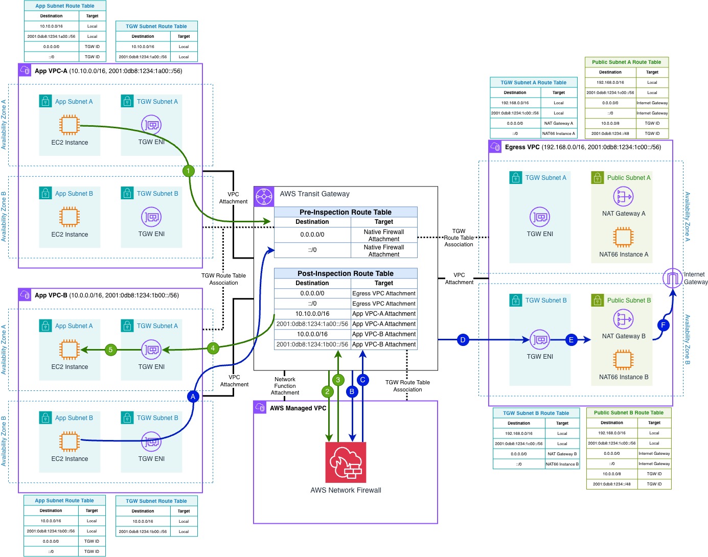
Figure 3: Transit Gateway Native Attachment architecture — AWS Network Firewall attaches directly to Transit Gateway as a managed network function attachment.
This architecture, shown in Figure 3, requires only a Transit Gateway with spoke VPC attachments, an AWS Network Firewall attached directly as a network function attachment, and Transit Gateway route tables directing traffic to the firewall attachment. Cross-account support is available through AWS RAM. You share the Transit Gateway, and the firewall owner creates the attachment. AWS manages automatic multi-AZ redundancy, and appliance mode is always enabled on transit gateway-attached firewalls, guaranteeing symmetric routing without manual configuration.
East-west traffic flow
- Source instance in VPC-A sends traffic to VPC-B. The spoke VPC route table (0.0.0.0/0 → TGW) directs it to Transit Gateway.
- Transit Gateway’s pre-inspection route table forwards the packet to the Network Firewall native attachment.
- Network Firewall evaluates the packet against the firewall policy. Allowed traffic returns to Transit Gateway via the post-inspection route table.
- The post-inspection route table forwards the packet to VPC-B’s attachment, delivering it to the destination.
- Return traffic follows the same inspection path in reverse. Appliance mode is always enabled, guaranteeing symmetric routing without manual configuration.
North-south traffic flow
Egress path:
- Source instance in VPC-B sends outbound internet traffic. The spoke VPC route table (0.0.0.0/0 → TGW) directs it to Transit Gateway.
- Transit Gateway’s pre-inspection route table forwards the packet to the Network Firewall native attachment.
- Network Firewall evaluates the packet. Allowed traffic returns to Transit Gateway via the post-inspection route table.
- The post-inspection route table forwards the packet to the Egress VPC attachment.
- NAT Gateway translates the source address and routes the packet through the Internet Gateway to the internet.
Return traffic follows the same path in reverse: Internet Gateway → NAT Gateway (stateful connection tracking) → Transit Gateway → Network Firewall (stateful match on existing connection) → post-inspection route table → VPC-B’s attachment, delivering it to the originating instance.
This pattern is well-suited for new deployments requiring centralized east-west and north-south inspection, as well as existing Transit Gateway environments looking to simplify their inspection architecture. It provides the same security capabilities as the Inspection VPC pattern including TLS inspection, stateful rule groups, and Suricata-compatible IPS rules with significantly lower operational overhead. AWS manages multi-AZ redundancy automatically, eliminating the need to provision and monitor firewall endpoints per Availability Zone. Additionally, flexible cost allocation lets you distribute data processing costs across accounts.
Important considerations: As of this writing, Transit Gateway native attachment is not supported with AWS Cloud WAN. Additionally, while this pattern eliminates the need for a dedicated inspection VPC, customers who require centralized internet egress with traffic inspection still need to create and manage a separate egress VPC containing a NAT Gateway and Internet Gateway. As of this writing, centralized internet egress through this pattern incurs double Transit Gateway data processing charges. Traffic is processed once when routed from the spoke VPC to the Network Firewall attachment, and again when forwarded from the firewall to the egress VPC containing the NAT Gateway. For further considerations and limitations, refer to the transit gateway-attached firewalls documentation.
Cost comparison
Let’s examine how these patterns compare from a cost perspective. The following table breaks down the billable components for each deployment pattern so you can identify which costs apply to your architecture. Use it to compare the fee structure across patterns based on your expected traffic volume, number of VPCs, and whether Transit Gateway is already part of your environment.
| Cost Component | Pattern 1: Inspection VPC | Pattern 2: Multiple VPC Endpoints | Pattern 3: Transit Gateway Native Attachment |
| Network Firewall primary endpoint hourly charges (per AZ) | Yes | Yes | Yes |
| Network Firewall secondary endpoints hourly charges (per AZ, reduced rate) | Not applicable | Yes (per VPC) | Not applicable |
| Network Firewall data processing charges (per GB) | Yes | Yes (Note – No data processing charges for secondary firewall endpoint) | Yes |
| Transit Gateway attachments hourly charges | Yes | Not applicable | Yes |
| Transit Gateway data processing charges (per GB) | Yes | Not applicable | Yes |
| NAT Gateway Hourly and data processing charges | Waived (when in same networking path as Network Firewall) | Waived (per VPC, when in same networking path as primary or secondary endpoint) | Waived (when in same networking path as Network Firewall) |
Table 2: Cost comparison between different Network Firewall deployment patterns
NAT Gateway discount: Standard NAT Gateway per-hour and data processing charges are waived on a one-to-one basis when the NAT Gateway is in the same region and configured in the same networking path as the Network Firewall endpoint. This applies to both primary and secondary endpoints. Refer to AWS Network Firewall pricing for details.
Cost at scale (many VPCs)
Patterns 1 and 3 have similar infrastructure costs at scale, both driven primarily by Transit Gateway per-attachment hourly fees. However, Pattern 3 incurs higher Transit Gateway costs for north-south traffic: because the firewall is a separate network function attachment and internet egress still requires a separate Egress VPC, north-south traffic crosses Transit Gateway twice (spoke → firewall, then firewall → Egress VPC), resulting in one additional attachment and one additional data processing hop compared to Pattern 1’s combined Inspection VPC where traffic exits to the internet locally after inspection.
The real savings with Transit Gateway Native Attachment are operational: no inspection VPC to design, deploy, monitor, or maintain. For organizations valuing engineering time, eliminating inspection VPC management can represent significant cost reduction beyond the infrastructure line items.
Pattern 2 is more expensive at scale because each additional VPC requires its own secondary firewall endpoints (one per Availability Zone), and the per-VPC endpoint cost accumulates as VPC count grows.
Cost at small scale (fewer VPCs)
At four or fewer VPCs, Pattern 2 becomes the most cost-effective option. Eliminating Transit Gateway entirely removes both attachment fees and data processing fees, which offsets the secondary endpoint costs. If your primary need is north-south inspection across a small number of VPCs, this pattern avoids Transit Gateway costs altogether.
For current pricing details, refer to AWS Network Firewall pricing and AWS Transit Gateway pricing.
Decision framework
The following decision tree helps you identify the deployment pattern that best matches your requirements. It evaluates constraints, inspection scope, routing complexity, and cost considerations to guide you to the right architecture for your environment. For most customers, Transit Gateway Native Attachment provides the simplest operational model. AWS deploys and manages the firewall endpoints in an AWS-managed VPC on your behalf, handling multi-AZ redundancy and symmetric routing inherently through the network function attachment model. This eliminates the need to manage a dedicated inspection VPC, its associated subnets, routing tables, or configure appliance mode on VPC attachments. The decision tree below helps you determine whether your specific requirements (such as AWS Cloud WAN compatibility, local per-VPC inspection, or granular routing control) warrant an alternative pattern.
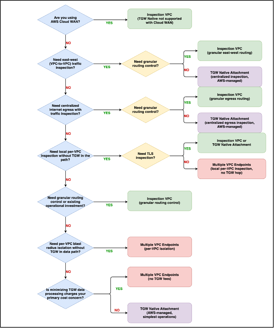
Figure 4: Network Firewall architecture pattern selection decision tree.
Considerations
Appliance mode behavior — For the Inspection VPC pattern, you must manually enable appliance mode on the Inspection VPC Transit Gateway attachment. For Transit Gateway Native Attachment, appliance mode is always enabled automatically.
TLS inspection support — TLS inspection is supported for Inspection VPC and Transit Gateway Native Attachment patterns. It is not supported for firewalls with VPC endpoint associations (Multiple VPC Endpoints pattern).
Cross-account sharing — All three patterns support cross-account deployments through AWS RAM. For Transit Gateway-based patterns, share the Transit Gateway. For Multiple VPC Endpoints, share the firewall policy via AWS RAM.
Cost allocation — Transit Gateway supports flexible cost allocation at multiple levels: Transit Gateway-level, attachment-level, and flow-level. With this, you can distribute costs across accounts for both the Inspection VPC and Transit Gateway Native Attachment patterns.
Migration risk — Existing Inspection VPC deployments continue to function — there is no deprecation. Migrate only when operational simplification outweighs migration effort. Test with a non-production VPC before rolling out to production.
Conclusion
AWS Network Firewall now gives you three inspection architectures, each optimized for different operational and cost requirements. Inspection VPC remains the right choice when your architecture requires granular routing control within a dedicated VPC or when your team has already built operational expertise around this model. Multiple VPC Endpoints provides a hybrid approach that combines centralized policy with distributed data paths. It is ideal for public-facing workloads that route directly through local firewall endpoints, environments where high data transfer volumes make avoiding Transit Gateway processing fees worthwhile, or small-scale deployments with four or fewer VPCs. Transit Gateway Native Attachment delivers the same security capabilities as the traditional Inspection VPC with significantly lower operational complexity. It eliminates the need to manage firewall subnets, route tables, and multi-AZ endpoints, making it well-suited for new deployments and organizations scaling beyond a handful of VPCs.
Evaluate your requirements against the comparison table and decision framework in this post and get started with the pattern that best fits your environment. For further reading, see the Transit gateway-attached firewalls in Network Firewall, AWS Network Firewall pricing, and AWS Transit Gateway pricing.
About the authors

Kunj Thacker