Networking & Content Delivery
Dynamic routing using Amazon VPC Route Server
Amazon VPC Route Server enables dynamic routing within Amazon Virtual Private Cloud (Amazon VPC) using Border Gateway Protocol (BGP). You can use Amazon VPC Route Server for effective and intelligent traffic control between cloud applications and on-premises systems. Amazon VPC Route Server uses BGP to provide advanced control over traffic paths, especially for failures, and it reduces manual overhead and human errors.
In this post, we explore multiple scenarios where application-level dynamic routing influences traffic delivery to instances and handles failover scenarios with minimal disruption.
Prerequisites
It is assumed that you are familiar with AWS networking concepts related to high availability and failover mechanisms, such as Amazon Elastic Compute Cloud (Amazon EC2), Elastic Network Interfaces (ENIs), Amazon VPC, VPC routing tables, and AWS Availability Zones (AZs). It is also assumed that you understand basic networking concepts such as IP addressing, CIDR blocks, network routing, BGP, and Bidirectional Forwarding Detection (BFD). This article does not focus on defining these fundamental services and concepts, but instead demonstrates how they can be used to implement floating IP solutions for application failover. For more background on AWS networking fundamentals, it is recommended to review the AWS documentation on VPC networking and the AWS Networking and Content Delivery posts. For details on VPC Route Server concepts, please refer to documentation here this Getting started guide.
Application connectivity scenarios
The movement of traffic inside an Amazon VPC is controlled by route tables. These route tables are associated with subnets, Internet Gateways (IGWs) and Virtual Private Gateways, and they allow you to define the path that traffic should take before it reaches the destination. For example, you can define routes in an IGW route table to direct traffic entering the VPC through a firewall before it reaches the intended destination. Similarly, you can direct traffic from subnets to a NAT Gateway, IGW, Peering Connections, or Virtual Private Gateway depending on your use case.
There are scenarios where applications (such as security or network processing applications) might need fine-grain control over the routing path of traffic to influence how traffic is sent to an application before it gets to its destination. These applications sit between the source and destination of network traffic to provide various network-related services. A common example is redirecting traffic to a security appliance for traffic inspection before sending traffic to its actual destination.
While static routes can be used to direct traffic to security appliances and other middleboxes, they have significant limitations (unless used with Gateway Load Balancer (GWLB)) . Static routes require manual intervention during failures, don’t automatically adapt to network changes, and become increasingly complex to manage as your network grows. This manual management increases the risk of human error and leads to longer recovery times during outages. Dynamic routing addresses these challenges by automatically updating route tables, providing better scalability, and enabling failover – all without manual intervention.
Note: AWS always recommends using GWLB for high availability and redundancy. You should only consider this solution if you’re using EC2 instances, with an application that does not support GWLB, for inspection.
VPC Route Server capabilities
VPC Route Server provides dynamic routing capabilities within VPC by using BGP routing protocol. Networking applications can use BGP routing protocol to update VPC route tables by allowing granular control of traffic within the VPC and automatic failover of traffic between instances deployed within or across different AZs within a VPC. The VPC Route Server can dynamically update VPC and IGW route tables with preferred IPv4 or IPv6 routes to achieve routing fault tolerance for workloads. When a failure occurs, the system can automatically reroute traffic within the VPC, which enhances the manageability of VPC routing and improves interoperability with third-party workloads. This capability is demonstrated in scenarios where, if an AZ fails, then the system can redirect traffic to resources in a different AZ, with the routing tables being automatically updated to reflect the new network paths.
In the following scenarios we discuss VPC Route Server routing capabilities.
Scenario #1: Using floating IP for application failover
In this scenario, we demonstrate how a floating IP address can be used to achieve seamless failover between two EC2 instances deployed across different AZs in a highly available architecture. You have a business-critical application running on an EC2 instance in AZ1. A standby EC2 instance is deployed in AZ2 for high availability. Your application is not integrated with GWLB, or GWLB is not available in an AWS environment (such as a Local Zone). Your objective is to provide a high availability mechanism for the application in the event of a failure of the primary instance or its underlying AZ.
You can use AWS CloudFormation in this aws-samples repo to deploy Scenario #1 in your AWS account. The CloudFormation template creates the following setup:
- VPC with three subnets across two AZs
- VPC route table for the three subnets created
- Create and attach IGW to VPC and create a default route to IGW in VPC route table
- Create and attach route server to VPC—the route server uses ASN 65000
- Create two VPC Route Server endpoints (RSEs) in each subnet (for high availability)
- Create route server peers
- Create two instances to simulate the HA application under test. We use Gobgp software.
- Each instance is running BGP using ASN 65001 and peers with RSEs in their prospective subnets
- Gobgp configurations are preconfigured as part of the user-data of the instances and are stored in gobgpd.conf file in the /home/ec2-user directory
- Create a test instance to ping the loopback IP of the high availability application under test
- You can use AWS Systems Manager to access the instances created
Solution overview
We use a floating IP address allocated from a non-VPC CIDR range that is used by the application. Clients use this IP to reach the application. In the event of a failure of the primary instance, the traffic destined for the floating IP is rerouted to the ENI of the standby instance in the second AZ. This minimizes the disruption in the application availability by using the floating IP concept with dynamic VPC routing without the need to update client configurations, or other manual intervention.

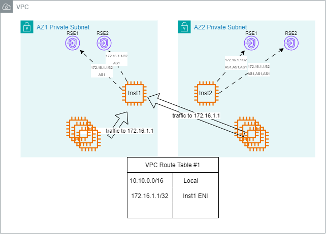
Figure 1. Instance#1 is active
As shown in Figure 1, the application operates in an active/standby mode across two AZs. Both EC2 instances advertise the same loopback IP address (for example 172.16.1.1/32) to the network through BGP peering with two VPC RSEs located in the same subnet. Two RSEs are used to make sure of redundancy and improve the availability of routing services.
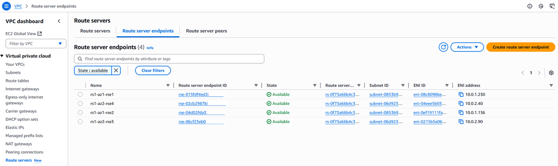 Figure 2. VPC Route Server endpoints

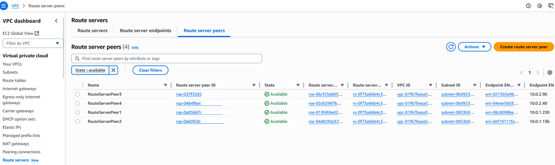 Figure 3. VPC Route Server peers
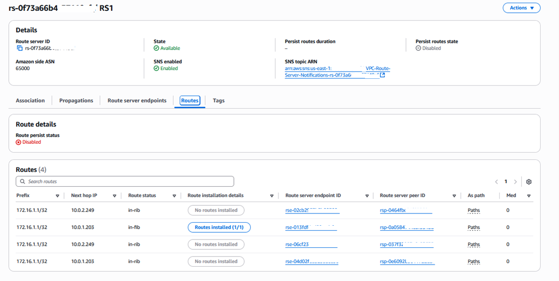 Figure 4. Route Server RIB table
To make sure that traffic is directed to the active instance, the application uses BGP AS Path attribute. The active instance advertises the route with a shorter AS Path, while the standby instance appends other AS numbers. This makes its path less preferred. BGP always chooses the shortest AS Path, making sure that the active instance is the preferred path. Other BGP attributes, such as Multi-Exit Discriminator (MED), can also be used to achieve similar routing preferences.
- Both active and standby instances advertise 172.16.1.1/32 through BGP to both RSEs in their prospective subnets.
- The VPC Route Server receives four advertisements for the same prefix. This is observed in Figure 4 where loopback 172.16.1.1/32 is received by four RSEs.
- Using BGP path selection rules, it prefers the route from the active instance due to the shorter AS Path. This is shown in Figure 4 where one of the four paths is selected and installed.
- The VPC Route Server identifies the ENI associated with the active instance and updates the VPC route table to forward traffic for 172.16.1.1/32 to ENI-A.
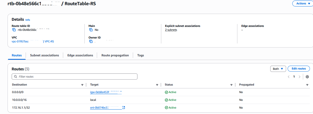 Figure 5. VPC route table updated with 172.16.1.1/32 pointing to the active instance ENI
You can inspect the Gobgp configuration by connecting to one of the instances (instance-rs-az1 or instance-rs-az2) using EC2 Session Manager.
The Gobgp configuration is in /home/ec2-user/gobgpd.conf.
sh-5.2$ sudo more /home/ec2-user/gobgpd.conf

[global.config]
as = 65001
router-id = "10.0.1.203"
[[neighbors]]
[neighbors.config]
neighbor-address = "10.0.1.230"
peer-as = 65000
[[neighbors.afi-safis]]
[neighbors.afi-safis.config]
afi-safi-name = "ipv4-unicast"
[[neighbors]]
[neighbors.config]
neighbor-address = "10.0.1.136"
peer-as = 65000
[[neighbors.afi-safis]]
[neighbors.afi-safis.config]
afi-safi-name = "ipv4-unicast"
Use the following command to check the BGP neighbor state. There should be two neighbors representing the two VPC RSEs in the instance subnet.
sh-5.2$ sudo /home/ec2-user/gobgp neighbor
Peer AS Up/Down State |#Received Accepted
10.0.1.136 65000 22:43:07 Establ | 0 0
10.0.1.230 65000 22:43:08 Establ | 0 0
Check that the loopback route is being advertised through BGP.
sh-5.2$ sudo /home/ec2-user/gobgp global rib
Network Next Hop AS_PATH Age Attrs
*> 172.16.1.1/32 0.0.0.0 22:42:21 [{Origin: ?}]
To test the routing setup, you can access the test instance “test-instance” using Systems Manager method. When you are logged in, you can ping 172.16.1.1 and you should get a reply that is originating from the active instance “instance-rs-az1”.
sh-5.2$ ping 172.16.1.1
PING 172.16.1.1 (172.16.1.1) 56(84) bytes of data.
64 bytes from 172.16.1.1: icmp_seq=1 ttl=127 time=0.712 ms
64 bytes from 172.16.1.1: icmp_seq=2 ttl=127 time=0.338 ms
64 bytes from 172.16.1.1: icmp_seq=3 ttl=127 time=0.378 ms
Failover detection and recovery
To simulate a failover, you can shut down the active instance (instance-rs-az1).
- If the active instance fails or becomes unreachable, then BGP detects the failure within the configured timeout.
- The VPC Route Server marks the BGP session with the active instance as down and withdraws the route from the RIB table.
- A BGP re-convergence process is triggered, and the route advertised by the standby instance is now chosen as the best path.
- The VPC route table is updated to forward traffic for 172.16.1.1/32 to the ENI of the standby instance (ENI-B).
- Traffic seamlessly transitions to the standby instance, maintaining application availability without client disruption.
To test the routing setup, you can access the test instance “test-instance” using the Systems Manager method. When you are logged in, you can ping 172.16.1.1 and you should get a reply that is originating from the now active instance “instance-rs-az2”.
sh-5.2$ ping 172.16.1.1
PING 172.16.1.1 (172.16.1.1) 56(84) bytes of data.
64 bytes from 172.16.1.1: icmp_seq=1 ttl=127 time=0.712 ms
64 bytes from 172.16.1.1: icmp_seq=2 ttl=127 time=0.338 ms
64 bytes from 172.16.1.1: icmp_seq=3 ttl=127 time=0.378 ms
To make sure of the rapid detection of failure, the BFD protocol can be enabled between the application and the RSEs. BFD significantly reduces the time needed to detect link or application failure.
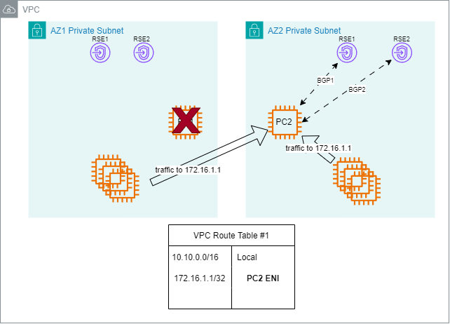 Figure 6. Instance2 took over as active
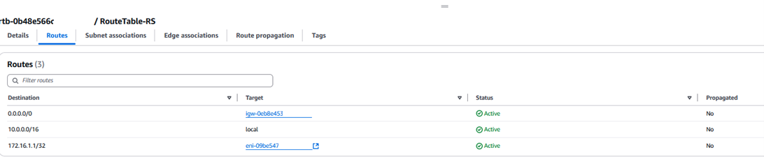 Figure 7. Route table updated to point to Inst2 ENI
This scenario demonstrates a robust method for implementing floating IP-based failover in AWS using standard routing protocols such as BGP and BFD. It enables fast, reliable, and transparent failover between AZs without needing DNS updates or manual intervention. This solution is ideal for high-availability workloads that need minimal downtime and maximum resiliency.
Scenario #2: VPC ingress traffic inspection
Consider the scenario where you have a centralized security model where firewall appliances (deployed as EC2 instances) inspect all north-south or east-west traffic in your VPC. These firewalls are critical to your security posture and must always be available to inspect and forward traffic. To maintain high availability, you deploy two firewall EC2 instances in separate AZs. Your goal is to make sure that if the active firewall fails, then traffic is seamlessly redirected to the standby instance.
In this scenario, we demonstrate how to implement high availability and failover for stateful firewall instances deployed across multiple AZs in AWS using VPC Route Server and dynamic route updates.
Solution overview
All traffic entering the VPC through the IGW is first routed to the firewall for inspection before it’s routed to the application subnet. Similarly, all traffic leaving the application subnet is first routed to the firewall for inspection before it is routed to the internet.
The following figure shows a firewall appliance installed on an EC2 instance in subnet A. The appliance inspects all traffic that travels from IGW to subnet B (application subnet) and from subnet B to IGW.
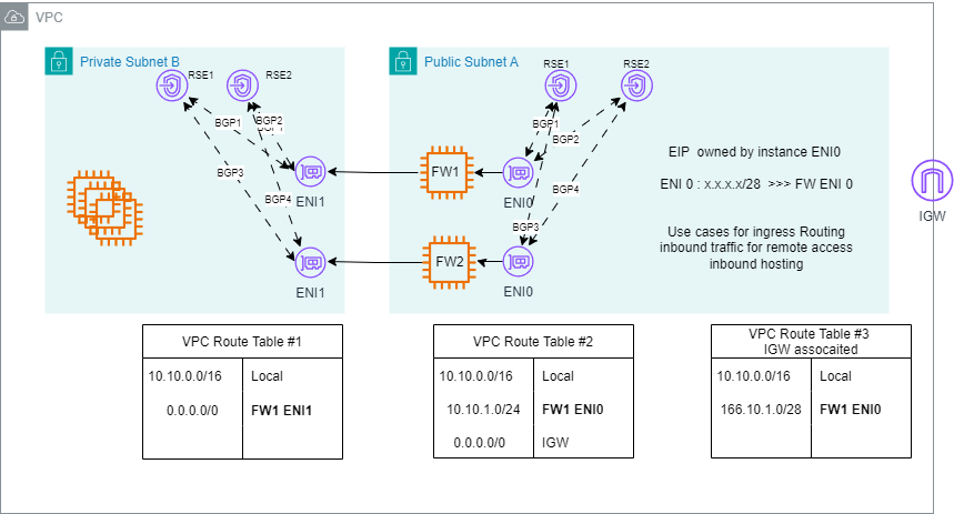 Figure 8. Scenario #2 where firewall 1 is active
Each firewall establishes four BGP sessions: two for subnet A and two for subnet B, covering both the application subnet and IGW route tables.
To make sure that only one firewall is used at a time, BGP path preference is manipulated using BGP metrics. We focus on the following metrics:
- AS_Path: BGP attribute that shows the sequence of Autonomous System numbers that a route has traversed, serving as both a loop prevention mechanism and a path selection criterion where shorter paths are preferred.
- MED (Multi-Exit Discriminator): BGP attribute used to influence inbound traffic by suggesting a preferred entry point when multiple connections exist between two autonomous systems, where a lower MED value is preferred.
The active firewall advertises prefixes with the most preferred BGP attributes, while the standby firewall advertises the same prefixes with less preferred attributes. In this scenario, we use AS path prepending where the standby firewall increases the AS path when advertising the prefix to RSE.
Internet gateway route table
The route tables associated with the IGW control the path that inbound internet traffic takes inside the VPC. Users typically use it to insert firewalls and other virtual network functions in the path of inbound internet traffic.
Both active and standby firewalls are pairing with VPC Route Server and are advertising the application subnet CIDR to RSEs. However, the standby firewall advertises the route with a longer AS path. VPC Route Server runs the BGP best path selection algorithm and installs the route advertised by active firewall.
The route table for the IGW subnet has the following route:
Application subnet CIDR ---> Active Firewall ENI.
VPC routes the traffic destined for the application subnet to the Active firewall ENI.
Application subnet route table
Both active and standby firewalls are paired with the VPC Route Server and are advertising 0.0.0.0/0 to RSEs. However, the standby firewall advertises 0.0.0.0/0 with a longer AS path. VPC Route Server runs the BGP best path selection algorithm, and it installs the route advertised by active firewall.
The route table for the application subnet has the following route:
0.0.0.0/0 ---> Active FW ENI.
This routes traffic from the application servers to the active firewall before it is routed to the internet.
Firewall subnet route table
The route table for the provider subnet has the following static routes:
0.0.0.0/0 ---> igw-id
This routes all traffic to the IGW.
Failover Detection with BFD
BFD is enabled on each BGP session between the firewalls and the VPC RSEs. BFD allows for rapid failure detection—typically within less than one second—by continuously exchanging control packets.
In the event of a firewall failure:
- BFD detects the failure of the BGP session between the active firewall and the RSEs
- The BGP session is marked DOWN by the RSEs
- RSEs withdraw the preferred routes (both internal and external prefixes) that were being advertised by the failed firewall
- BGP re-convergence occurs—the RSEs choose the alternative (standby) route advertised by the healthy firewall
- This route becomes active in the VPC routing control plane
- Traffic is automatically redirected to the standby firewall
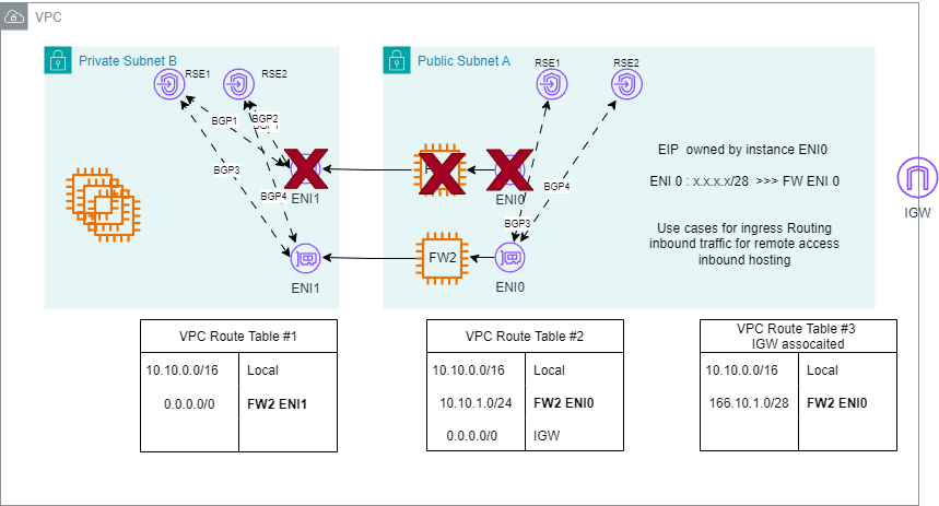 Figure 9. Failure of FW1 led to traffic being rerouted to FW2
Failback/recovery
When the failed firewall recovers and re-establishes BGP and BFD sessions:
- It resumes advertising the preferred BGP attributes.
- The RSEs detect the more attractive route and switch back traffic to the recovered firewall.
This process can be automated or controlled through admin policy (for example preemptive or non-preemptive failover)
Advantages of using VPC Route Server BGP+BFD-Based Failover:
- Fast convergence: Sub-second failure detection with BFD
- Fully automated: No scripts or manual intervention
- Scalable: Works across multiple prefixes and instances
- Cloud-native control: Integrated with the VPC routing layer
- Protocol standardization: Uses industry-standard BGP behavior
Considerations
- Routing re-convergence includes some downtime. Consider GWLB as your first option for application failover if the application is integrated with GWLB.
- Make sure that route propagation is disabled if you’re manually controlling routes.
- Use BFD or other rapid-failure-detection tools for faster convergence.
- Make sure of symmetric routing paths if performing return-path inspection.
- Enable monitoring and alerting to track health, route changes, and failover events.
Conclusion
In this post, we explored how you can use Amazon VPC Route Server to build scalable, fault-tolerant, and secure network designs in the cloud by enabling failover for critical applications and implementing high-availability architectures. We walked you through two different architectural patterns and provided implementation details. VPC Route Server unlocks advanced routing capabilities within AWS by integrating industry-standard BGP and BFD protocols into native VPC networking. To get started with VPC Route Server today, you can refer to the documentation and Amazon VPC Route Server Get started tutorial.
An update was made on September 15, 2025: An earlier version of this post included figures with outdated AWS architecture icons. The post has been updated to reflect the current AWS architecture icon set.
About the authors

Ammar Latif
Ammar is a Principal Solutions Architect in the AWS Worldwide Telecom Business Unit. He enjoys helping customers in using cloud technologies to address their business challenges. Throughout his career, Ammar has collaborated with a number of Telecom and Media customers globally. Ammar holds a Ph.D. from New Jersey Institute of Technology.

Akshay Choudhry
Akshay is a Principal Product Manager in the Networking and Security Services Team at Amazon Web Services. He is focused on making Virtual Private Clouds more intuitive and secure for the millions of customers running their workloads on AWS. In his free time, he enjoys exploring the outdoors, trying out new restaurants, and spending time with friends and family.