AWS Architecture Blog
Understand resiliency patterns and trade-offs to architect efficiently in the cloud
This post was originally published in June 2022 and is now updated with more information on efficiently architecting resilient patterns in the cloud.
Architecting workloads for resilience on the cloud often need to evaluate multiple factors before they can decide the most optimal architecture for their workloads.
Example Corp has multiple applications with varying criticality, and each of their applications have different needs in terms of resiliency, complexity, and cost. They have many choices to architect their workloads for resiliency and cost, but which option suits their needs best? What should they consider when choosing the patterns most appropriate for the needs of their applications?
To help answer these questions, we’ll discuss the five resilience patterns in Figure 1 and the trade-offs to consider when implementing them: 1) design complexity, 2) cost to implement, 3) operational effort, 4) effort to secure, and 5) environmental impact. This will help you achieve varying levels of resiliency and make decisions about the most appropriate architecture for your needs. Our intent is to provide a high-level approach to structure conversations on trade-offs associated with each of these patterns. For a deeper dive on each pattern, please navigate to the Further reading section at the end of this post.
Note: these patterns are not mutually exclusive; you may decide to implement a combination of one of more patterns.
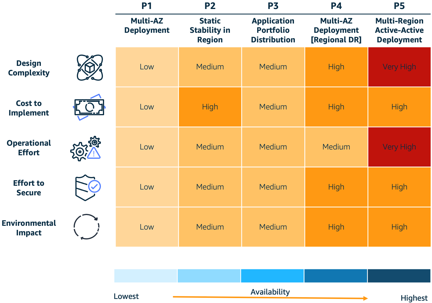
Figure 1. Resilience patterns and trade-offs
What is resiliency? Why does it matter?
The AWS Well-Architected Framework defines resilience as having “the capability to recover when stressed by load (more requests for service), attacks (either accidental through a bug, or deliberate through intention), and failure of any component in the workload’s components.”
To meet your business’ resilience requirements, consider the following core factors as you design your workloads:
- Design complexity – An increase in system complexity typically increases the emergent behaviors of that system. Each individual workload component has to be resilient, and you’ll need to eliminate single points of failure across people, process, and technology elements. Customers should consider their resilience requirements and decide if increasing system complexity is an effective approach, or if keeping the system simple and using a disaster recovery (DR) plan is be more appropriate.
- Cost to implement – Costs often significantly increase when you implement higher resilience because there are new software and infrastructure components to operate. It’s important for such costs to be offset by the potential costs of future loss.
- Operational effort – Deploying and supporting highly resilient systems requires complex operational processes and advanced technical skills. For example, customers might need to improve their operational processes using the Operational Readiness Review (ORR) approach. Before you decide to implement higher resilience, evaluate your operational competency to confirm you have the required level of process maturity and skillsets.
- Effort to secure – Security complexity is less directly correlated with resilience. However, there are generally more components to secure for highly resilient systems. Using security best practices for cloud deployments can achieve security objectives without adding significant complexity even with a higher deployment footprint.
- Environmental impact – An increased deployment footprint for resilient systems may increase your consumption of cloud resources. However, you can use trade-offs, like approximate computing and deliberately implementing slower response times to reduce resource consumption. The AWS Well-Architected Sustainability Pillar describes these patterns and provides guidance on sustainability best practices.
Pattern 1 (P1): Multi-AZ
P1 is a cloud-based architecture pattern (Figure 2) that introduces Availability Zones (AZs) into your architecture to increase your system’s resilience. The P1 pattern uses a Multi-AZ architecture where applications operate in multiple AZs within a single AWS Region. This allows your application to withstand AZ-level impacts.
As shown in Figure 2, Example Corp deploys their internal employee applications using the P1 pattern. These applications are low business impact and therefore have lower requirements for resiliency.
Example Corp deploys their low-business-impact applications as a single Amazon Elastic Compute Cloud (Amazon EC2) instance managed by an Auto Scaling group. Amazon EC2 uses health checks to automatically detect faults. If an AZ fails, Amazon EC2 prompts an Amazon EC2 Auto Scaling group to recreate their application in another unaffected AZ.

Figure 2. Multi-AZ deployment pattern (P1)
Trade-offs
P1 is low in several categories and mitigates a disruption to the AZ hosting the application, but this comes at the expense of application recovery. If an AZ is down, it will disrupt end users’ access to the application while the new resources are being re-provisioned in a new AZ. This is known as bi-modal behavior.
Pattern 2 (P2): Multi-AZ with static stability
P2 uses multiple instances across multiple AZs within a Region to increase resilience. The pattern uses static stability to prevent bimodal behavior. Statically stable systems remain stable and operate in one mode, irrespective of changes to their operating environment. A key benefit of a statically stable system on AWS is it reduces complexity of recovery during a disruption thanks to pre-provisioned resource capacity. Any resources needed to maintain operations during a disruption, such as the loss of resources in an AZ, already exist and AWS service control planes do not need to be available for recovery to be successful. To learn more about static stability, data planes and control planes read the builder’s library article Static stability using Availability Zones.
As shown in Figure 3, Example Corp has a customer-facing website that has a lower tolerance for downtime. Any time the website is down, it could result in lost revenue. Because of this, the website requires two EC2 instances that are provisioned within two AZs. Using health checks, when the AZ becomes impaired, the website continues to operate as the Elastic Load Balancer diverts traffic away from the impacted AZ. For more on using health checks, see the Implementing health checks article in The Amazon Builder’s Library.

Figure 3. Multi-AZ with static stability pattern (P2)
Trade-offs
P2 mitigates an AZ disruption without downtime to application clients but must be weighed against cost concerns. P1 is less expensive from an infrastructure cost perspective, as it provisions less compute capacity and relies on launching new instances in case of a failure. However, P1’s bimodal behavior can affect your customers during large-scale events.
Implementing P2 requires your application to support distributed operation across multiple instances. If your application can support this pattern, you can deploy your workload to all available AZs (usually 3 or more) across the Region. This will reduce costs associated with over-provisioning because you only have to provision 150% of your capacity across three AZs compared with the 200% in two AZs (as mentioned in our earlier example).
Pattern 3 (P3): Application portfolio distribution
P3 uses a Multi-Region pattern to increase functional resilience, as demonstrated in Figure 4. It distributes different critical applications in multiple Regions.
Example Corp provides banking services, like credit balance checks, to consumers on multiple digital channels. These services are available to consumers via a mobile application, contact center, and web-based applications. Each digital channel is deployed to a separate Region, which mitigates against a regional service disruption.
For example, a Region with the customers’ mobile application may have a disruption that causes the mobile app to be unavailable, but customers can still access banking services via online banking deployed in an alternate Region. Regional service disruptions are rare, but implementing a pattern like this ensures your users retain access to business-critical services during disruptions.

Figure 4. Application portfolio distribution pattern (P3)
Trade-offs
P3 mitigates the possibility of a regional service disruption impacting a multitude of systems at the same time. Operating an application portfolio that spans multiple Regions requires significant operational planning and management. Isolated functional elements may depend on common downstream systems and data sources that are deployed in a single Region. Therefore, Region-wide events may still cause disruption, but the impact surface area should be reduced.
Pattern 4 (P4): Multi-AZ deployment (multi-Region DR)
Example Corp operates several business-critical services that have a very low tolerance for disruption, such as the ability for consumers to make bank payments. Example Corp reviewed the four common patterns for DR (as defined in Disaster Recovery of Workloads on AWS: Recovery in the Cloud) and decided to use the following sub-patterns for their multi-Region applications:
- Pilot Light – This pattern works for applications that require RTO/RPO of 10s of minutes. Data is actively replicated and application infrastructure is pre-provisioned in the DR Region. Cost optimization is a key driver here, as the application infrastructure is kept switched-off and only switched-on during the restore event.
- Warm Standby – This pattern improves restore times significantly compared with pilot light by keeping your applications running in the DR Region but with a reduced capacity. Application infrastructure will be scaled up during a DR event, but this can typically be automated with minimal manual effort. This pattern can achieve RTO/RPO of minutes if implemented correctly.
Trade-offs
P4 mitigates a disruption to a regional service while reducing mitigation costs. Regional DR patterns increase deployment complexity as infrastructure changes need to be synchronized across Regions. Testing resilience is also significantly more complex and include simulating regional disruptions. Using Infrastructure as Code to automate deployments can help alleviate these issues.
Pattern 5 (P5): Multi-Region active-active
Example Corp’s core banking and Customer Relationship Management applications have zero tolerance for disruption. They use the P5 pattern for deploying these applications because it has an RTO of real-time and an RPO of near-zero data loss. They run their workload simultaneously in multiple Regions, allowing them to serve traffic from all Regions simultaneously. This pattern not only mitigates against regional disruptions but also addresses their zero tolerance requirements (Figure 5).

Figure 5. Multi-Region active-active pattern (P5)
Trade-offs
P5 mitigates the disruption of a regional service, and invests additional costs and complexity to deliver a RTO of near zero. Multi-active deployments are generally complex, as they include multiple applications that collaborate to deliver required business services. If you implement this pattern, you’ll need to consider the fact that you’re introducing asynchronous replication for data across Regions and the impact that has on data consistency.
Operating this pattern requires a very high level of process maturity, so we recommend customers gradually build towards this pattern by starting with the deployment patterns described earlier.
Conclusion
In this blog post, we introduced five resilience patterns and trade-offs to consider when implementing them. In an effort to help you find the most efficient architecture for your use case, we demonstrated how Example Corp evaluated these options and how they applied them to their business needs.
Further reading
- AWS Well Architected Framework – Resilience Pillar
- Building Resilient Well-Architected Workloads Using AWS Resilience Hub
- Disaster Recovery of Workloads on AWS: Recovery in the Cloud
- Disaster Recovery (DR) Architecture on AWS, Architecture Blog series
- AWS Multi-Region Fundamentals whitepaper
Looking for more architecture content?
AWS Architecture Center provides reference architecture diagrams, vetted architecture solutions, Well-Architected best practices, patterns, icons, and more!