AWS for Industries
Secure, remote monitoring and control of a PLC from AWS
Introduction
This post is a step-by-step guide for connecting a Programmable Logic Controller (PLC) to the Amazon Web Services (AWS) cloud. With Inductive Automation Ignition installed in a cloud based architecture, the hardware system described here can be used for remotely monitoring and controlling industrial assets, or it can be used to learn about cloud-enabled Operational Technology (OT). It is suited to Control System Engineers, OT specialists, and curious technical professionals.
The architecture in this post is a simplified model of the cloud OT environments operated by large, industrial AWS users. AWS-hosted applications such as Ignition are used by these companies to control and monitor geographically distributed sites, such as renewable power plants, mines, oil fields and offshore facilities. AWS hybrid networking extends edge-located networks to the AWS Cloud, enabling the benefits of on-demand compute and data storage, next generation firewall technology, secure remote access patterns and streamlined connectivity to IT. A secure OT-only environment on AWS enables the application of AI and advanced analytics to asset data.
System overview
The post architecture uses AWS-validated hardware components chosen for enterprise-grade reliability and optimized cost-efficiency. You need the following devices, as well as a personal computer with a network interface to program them.
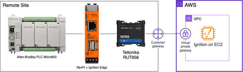 Figure 1: Post architecture
- Allen-Bradley Micro850 programmable logic controller (or any PLC).
- Teltonika RUT956 industrial cellular router with internet access.
- Revolution Pi Core SE (or similar edge-of-network device) to host Ignition Edge.
- An AWS account to host Ignition.
Teltonika’s RUT956 router is reliable and enables secure site-to-site VPN integration. It features dual-SIM support and certificate-based authentication, making it appropriate for remote industrial deployments. Its cost-effectiveness, ease of configuration, and scalability provide reliable uptime and data integrity, while supporting future growth in industries such as mining and clean energy.
AWS Site-to-Site VPN resilience and security
The Teltonika RUT956 supports a “dynamic” AWS Site-to-Site VPN using Border Gateway Protocol (BGP). BGP enables automatic failover between the two VPN tunnels and route advertisement.
Site-to-Site VPN operates over a public or private cellular network connection with IPSec encryption. Private networks are recommended for the most critical OT systems. AWS Direct Connect is an alternative private connectivity option.
The RUT956 supports certificate-based authentication in its role as a Customer gateway device. This is more secure and practical than using SIM cards with static IP addresses. We provision the certificates using AWS Private CA in a two-level multi-tiered hierarchy.
In non-production environments, you should delete the certificate authorities (CAs) immediately after generating the certificates to minimise costs. In a production deployment, the CAs must be left active to issue new certificates for new and expired connections. AWS Private CA can be shared across AWS accounts within a company.
Step 1. Create AWS Private CAs and issue private certificates
1.1 Create AWS Private CAs
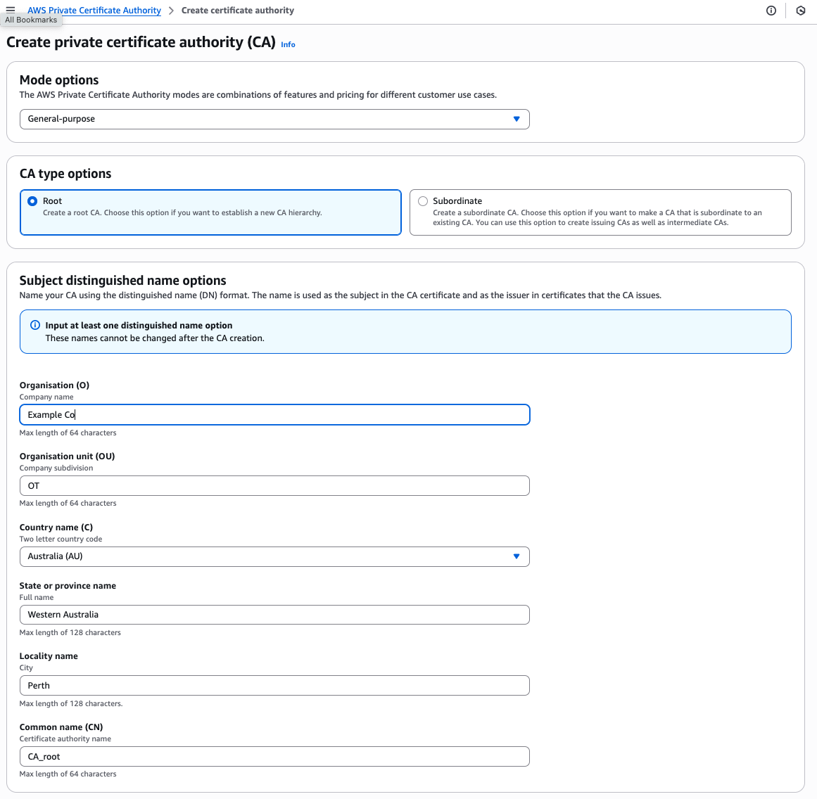
Figure 2: Creating a private certificate authority.
1. Log in to AWS. Search and navigate to AWS Private Certificate Authority and choose Create a private CA.
2. Leave Mode options as General-purpose.
3. Create a Root CA by choosing Root under CA type options.
4. Create arbitrary entries for the Subject distinguished name options.
5. Leave Key algorithm options as RSA 2048.
6. Leave the remaining options unchanged. Read and acknowledge the Pricing statement.
7. Choose Create CA.
8. Wait for the Status to change to Pending certificate.
9. Choose Actions > Install CA certificate. Leave the default options and choose Confirm and install.
10. Create a subordinate CA by repeating Steps 1 through 8, but choose Subordinate under CA type options. Repeat the same entries for Step 4 but provide a different Common name (CN).
11. Choose Actions > Install CA certificate.
12. Under Select CA type, choose AWS Private CA.
13. Under Select parent CA, choose your newly created Root CA.
14. Under Specify the subordinate CA certificate parameters enter a validity date up to the displayed validity date of the Parent CA.
15. Leave the Signature algorithm and Path length default values. Choose Confirm and install.
16. Confirm that your Root and Subordinate CA Status is Active.
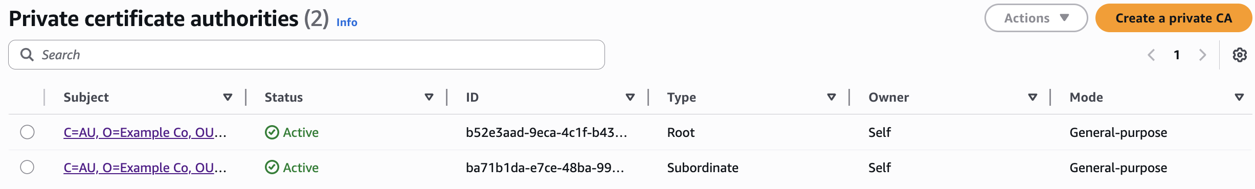
Figure 3: Active root and subordinate private certificate authorities.
1.2 Request a certificate
1. Navigate to AWS Certificate Manager and choose Request a certificate.
2. Choose Request a private certificate and choose Next.
3. Choose the Subordinate CA from the previous section under Certificate authority.
4. Enter “example.com” for the Fully qualified domain name.
5. Leave Key algorithm as RSA 2048. Read and acknowledge the Billing acknowledgement.
6. Choose Request.
7. Choose the certificate link when the certificate is issued.
8. Choose Export. Enter and record a passphrase. Read and acknowledge the Billing acknowledgement.
9. Choose Generate PEM Encoding. Download and store the files.
Step 2. Create the Site-to-Site VPN configuration on AWS
Navigate to VPC dashboard. First, create a basic Amazon Virtual Private Cloud (Amazon VPC). Then, create the AWS Site-to-Site VPN to connect this VPC to Ignition Edge running on the edge device. Later you install Ignition in the VPC.
2.1 Create a VPC
1. Confirm choice of an AWS Region near your location (top right of console) and choose Create VPC.
2. Choose VPC and more under Resources to create.
3. Create a Name tag auto-generation label (optional).
4. Choose 1 for Number of Availability Zones (AZs), 1 for Number of public subnets, and 0 for Number of private subnets.
5. Choose None for VPC endpoints. This leaves you with 1 subnet, 1 route table, and 1 network connection in the Preview.
6. Leave the remaining options as default and choose Create VPC.
2.2 Create virtual private gateway
1. Choose Virtual private gateways in the left-hand menu. Choose Create virtual private gateway.
2. Add a memorable Name tag. Leave the ASN as Amazon default ASN and choose Create virtual private gateway.
3. The gateway is available when State changes to Available.
4. Choose the radio button next to your new virtual private gateway, and choose Attach to VPC under Actions.
5. Choose the VPC you just created and choose Attach to VPC.
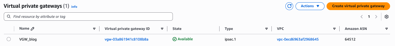
Figure 4: The virtual private gateway.
2.3 Create customer gateway
1. Choose Customer gateways in the left-hand menu and choose Create customer gateway.
2. Add a memorable Name tag. You can leave the BGP ASN as is and leave the IP Address field blank. If your SIM card has a static IP address, then this is where you would enter it.
3. Choose your newly created example.com private certificate under Certificate ARN.
4. Choose Create customer gateway.
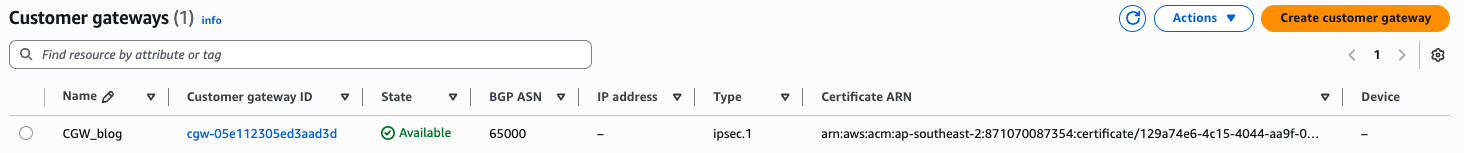 Figure 5: The customer gateway.
2.4 Create the Site-to-Site VPN
1. Choose Site-to-Site VPN connections in the left-hand menu and choose Create VPN connection.
2. Create a Name tag (optional) and leave Target gateway type as Virtual private gateway.
3. Choose your new Virtual private gateway and Customer gateway ID.
4. Choose Dynamic (requires BGP) under Routing options.
5. Leave Local IPv4 network CIDR and Remote IPv4 network CIDR fields blank.
6. You can open the Tunnel 1 options and Tunnel 2 options and choose Enable under Tunnel activity log. This step is optional and necessitates familiarity with Amazon CloudWatch log groups. However, it can make troubleshooting clearer.
7. Choose Create VPN connection and wait for the State to become Available.
8. Choose the radio button for your new VPN and choose Download configuration. Choose the Generic options for Vendor and Platform. Choose Vendor Agnostic under Software, and ikev2 under IKE version. This file contains the necessary data shown in Table 1. Creating your own table can make the next steps easier.
9. Navigate to AWS Certificate Manager and find the auto-generated certificates with Domain name ending in endpoint-0 and endpoint-1. Choose each Certificate ID link and export the corresponding Certificate body file for each endpoint. Name each file to track which endpoint it belongs to.
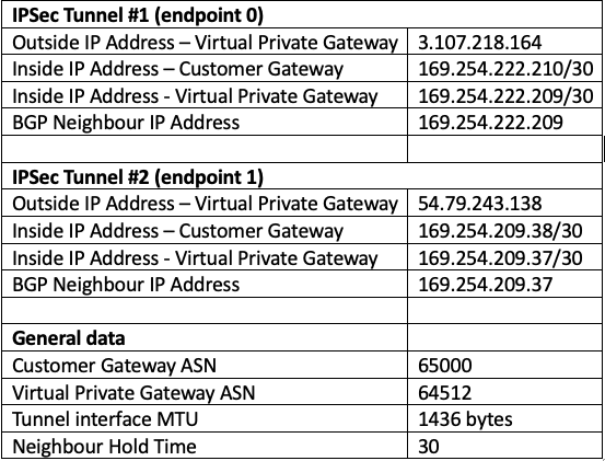 Table 1: Data extracted from the AWS VPN configuration file for easy reference (example).
Step 3. Connect the Teltonika RUT956 to Site-to-Site VPN
The RUT956 firmware version used in this post is RUT9M_R_00.07.13.4.
3.1 Create two IPsec tunnels
1. Power on your RUT956 and log in to the web interface. Make sure that the device has internet connectivity.
2. Set RUT956 LAN interface IP address (optional). Navigate to Network > LAN and choose Edit. Set static IP in IPv4 address to your desired address. We are using 10.77.0.1. Reconnect to the router.
3. Connect two IPsec tunnels to the two AWS VPN endpoints. Navigate to Services > VPN > IPsec, add a new instance, and name it “Tunnel1” or similar.
4. In the pop-up menu, switch on Enable. At Remote endpoint enter the Outside IP address that is provided in your VPN’s Tunnel details in the AWS console. This address is also contained in the configuration file that you downloaded in the previous section. In this example, the first tunnel IP address is 3.107.218.164.
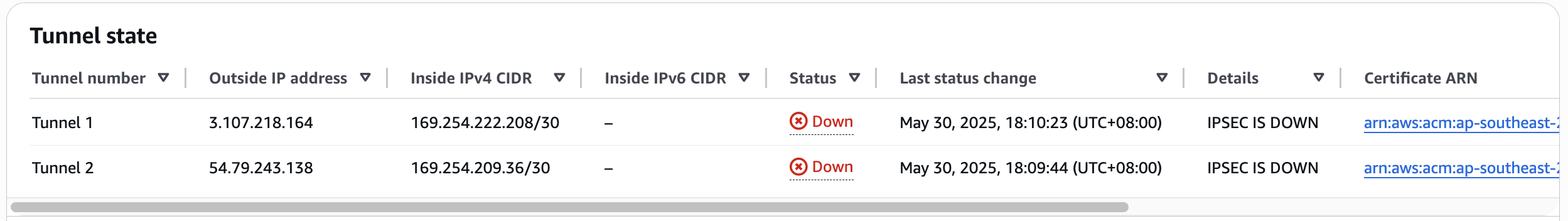 Figure 6: Tunnel states in the AWS console.
5. Choose X.509 for the Authentication method. For the Key, browse to the private key file you downloaded in Step 1. In the console, this file was called Certificate private key. Enter the passphrase that you defined in Step 1 in the field after this.
6. Next to Local certificate, browse to the Certificate body file that you downloaded in Step 1. This may be called certificate.txt.
7. Next to CA certificate, browse to the Certificate chain file that you downloaded in Step 1.
8. Skip Local identifier and Remote identifier.
9. Go to the Advanced settings page for IPsec configuration and upload the endpoint-0 certificate (downloaded in the previous section) to Remote certificate.
10. Enable Route based IPsec and enter the Inside IP Address – Customer Gateway for your first tunnel (found in the VPN configuration file).
11. Enter the MTU from the VPN configuration file (for example 1436) and change Key exchange to IKEv2.
12. Under Proposal settings, change the Phase 1 and Phase 2 proposals DH Group to MODP2048.
13. Leave the remaining settings as default and choose Save & Apply.
14. Repeat Steps 3 through 13 for a second tunnel (for example named Tunnel2).
15. Enable both tunnels with the toggle switch and choose Save & Apply.
16. You should see the Status of each tunnel change to Connected. You can troubleshoot connectivity issues by choosing the Logs link.
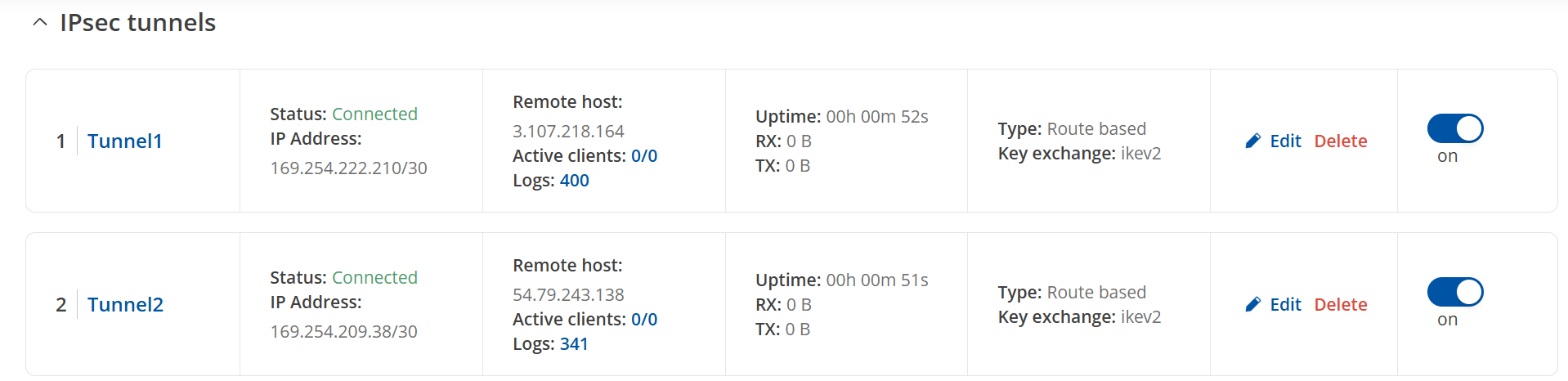 Figure 7: Connected IPsec tunnels.
17. In the AWS console, the Tunnel state should now indicate IPSEC IS UP as shown below. Status changes when BGP is enabled.
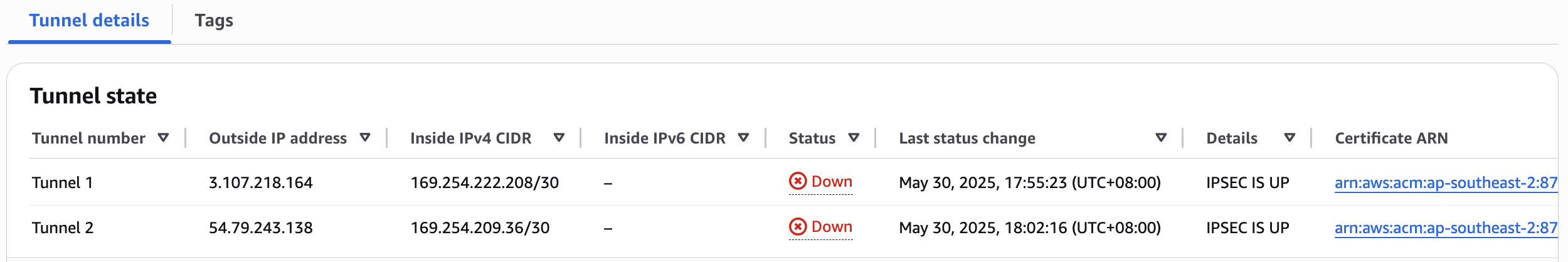
Figure 8: IPsec tunnel connections in AWS.
3.2 Enable BGP over IPsec
1. Navigate to System > Package Manager. Find and install the BGP daemon package.
2. Navigate to the new menu that becomes available at Network > Routing > Dynamic Routes.
3. Enable the service under BGP – global settings.
4. Choose Edit to edit the pre-existing BGP instance. Create a new instance if none exists.
5. Enable the instance and enter the Customer Gateway ASN number from your configuration file at AS.
6. At Network enter the LAN IP address space to advertise to the AWS VPN. In our example it is 10.77.0.0/16.
7. Choose Connected routes under Redistribution options. This shares the RUT956’s LAN IP address space with your AWS environment.
8. Set eBGP Requires Policy to off.
9. Scroll down, enter BGP peer name “tun1”, and choose Add.
10. Enable the peer and add the Virtual Private Gateway ASN (from your VPN Configuration file) at Remote AS.
11. Enter the “Neighbour IP Address” for the first tunnel in your VPN configuration file at Remote address.
12. Add a Weight = 100. Keepalive timer = 10 and Holdtime = 30. Choose Save & Apply.
13. Repeat for second BGP peer but enter 200 for the Weight. The VPN preferences the first tunnel. Choose Save & Apply. Enable both BGP peers and choose Save & Apply again. Make sure that the BGP instance is enabled and choose Save & Apply again.
14. Navigate to Status > Routes > Dynamic and confirm that the BGP states are established.
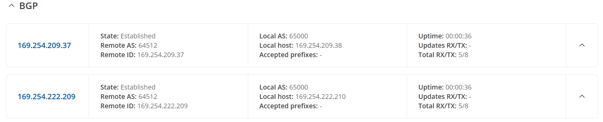
Figure 9: BGP instances established.
15. In AWS, confirm that the Tunnel state for your VPN shows that the Status is up and BGP routes are being received.
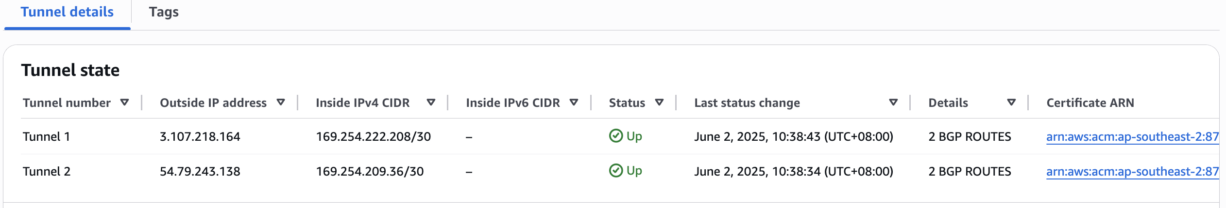
Figure 10: BGP status in AWS.
16. Navigate to your VPC’s main route table and enable route propagation. Choose Save.
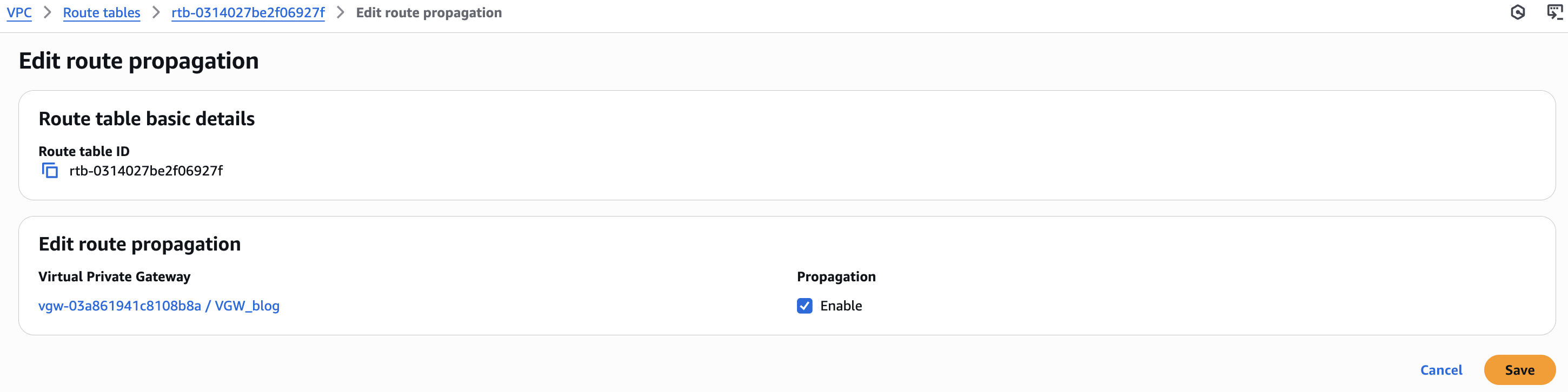 Figure 11: Enable VPC route propagation.
17. Confirm the RUT956 routes are appearing in the VPC Route Table. In this example, the LAN address space 10.77.0.0/24 is shared, so the Amazon Elastic Compute Cloud (Amazon EC2) Ignition instance can “see” and communicate with the Ignition Edge device attached to the RUT956 LAN, wherever it is in the world.
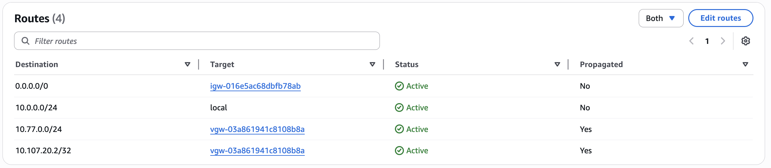
Figure 12: VPC Route Table.
Step 4. Ignition Edge and PLC setup
Ignition Edge captures, processes, visualizes and transmits data from connected devices in edge-of-network locations. You install Ignition Edge on a RevPi Core SE base module to collect data from the PLC. The RevPi is an industrialized Raspberry Pi. Make sure that the RevPi is mounted and connected properly.
The RevPi, PLC, and your programming computer can be connected through the RUT956’s Local Area Network (LAN) interface. Find their IP addresses in the RUT956 interface at Status > Network > LAN. Fix the IP addresses by choosing Create static. You can connect to the RevPi terminal using SSH.
You may need to adjust firewall settings on the RUT956 to enable some of the following communications. When troubleshooting, experiment with the General settings under Network > Firewall by setting Input, Output, and Forward to Accept. Then, check the Traffic Rules for blocking selective rules.
4.1 Install Ignition Edge on the RevPI
1. Download the Ignition Edge System Installer zip file from the Inductive Automation site and transfer it to the RevPi using SCP or a USB drive. The RevPi needs the 32-bit ARMHF version of the Ignition Edge Linux installer. We’re using Ignition-Edge-linux-armhf-32-8.1.48.zip.
2. Unzip the file and start Ignition Edge with the following commands:
pi@revpi:~ $ unzip Ignition-Edge-linux-armhf-32-8.1.48.zip -d ignition-edge
pi@revpi:~ $ cd ignition-edge
pi@revpi:~ $ sudo chmod +x ignition.sh ignition-util.sh gwcmd.sh
pi@revpi:~ $ sudo ./ignition.sh start
3. You can enable the service to start automatically upon reboot by adding the following line to your rc.local file.
/usr/local/ignition/ignition.sh start
4.2 Ignition Edge Gateway configuration
When Ignition is installed, each instance of its service is referred to as a Gateway. For this architecture, we are going to describe how to configure basic features, so the Edge Gateway is capable of the following:
1. Connecting to a PLC using Ignition’s native communications driver
2. Creating tags and getting data flowing from the PLC into the Edge Gateway
3. Configuring a Gateway Network connection from the Edge Gateway to the Ignition Gateway in the EC2 instance in AWS.
Now that Ignition Edge is installed and the service is running, log in to the user interface from your programming computer:
1. Using the browser of your preference, go to the Ignition Gateway configuration page at the following address:
http://[IP address of the RevPi]:8088
2. After setting the username and password, you should see the Gateway Configuration page.
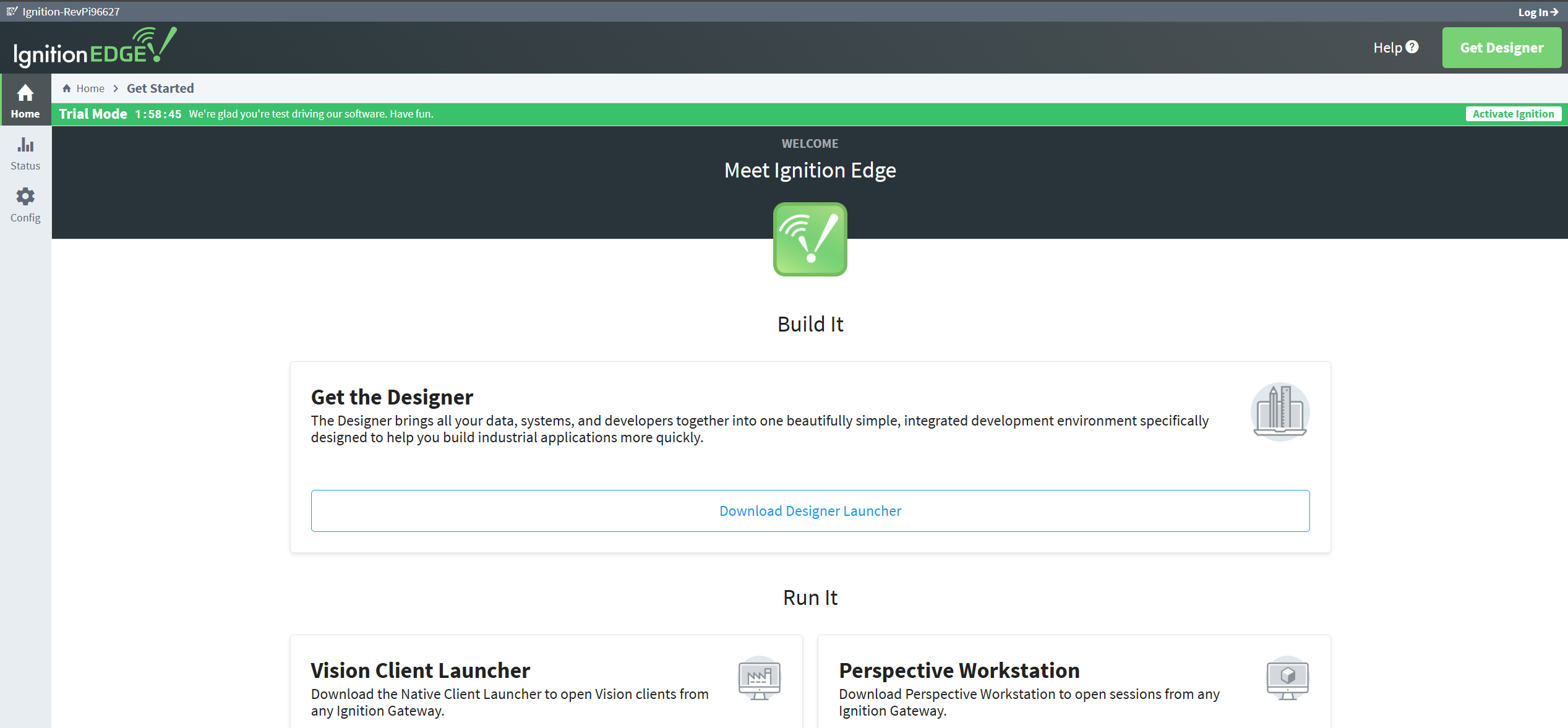
Figure 13: Ignition Edge home page.
3. Configure a connection to an Allen Bradley Micro850 PLC. The process is similar for most commonly available PLCs. At this link you can find information for the most common device driver configurations. Choose the Config button in the vertical menu on the left of the page. If prompted, log in with your new username and password.
4. Choose Device Connections on the left menu and then choose Create new Device.
5. Choose the device to which you are connecting and choose Next.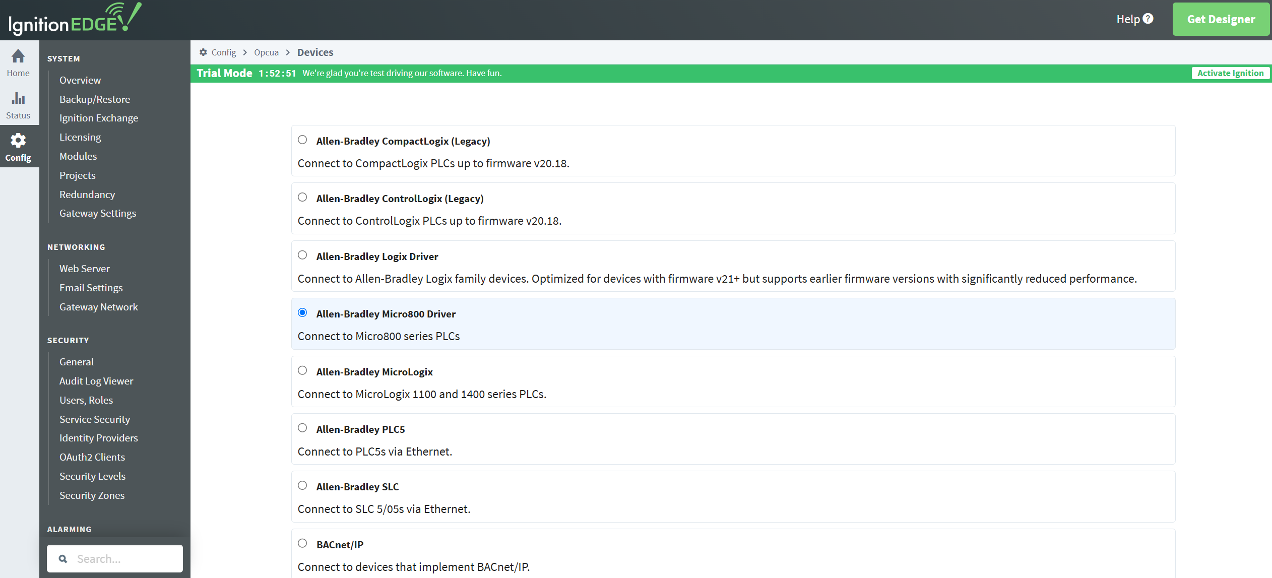
Figure 14: PLC device selection.
6. Provide a name and an IP address for the device to which Ignition is connecting. Choose Create New Device to save the configuration.
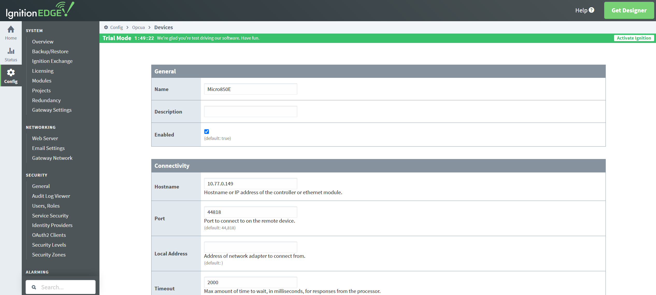
Figure 15: Setting the PLC device particulars.
7. The device configuration is done, and its status is displayed as Connected.
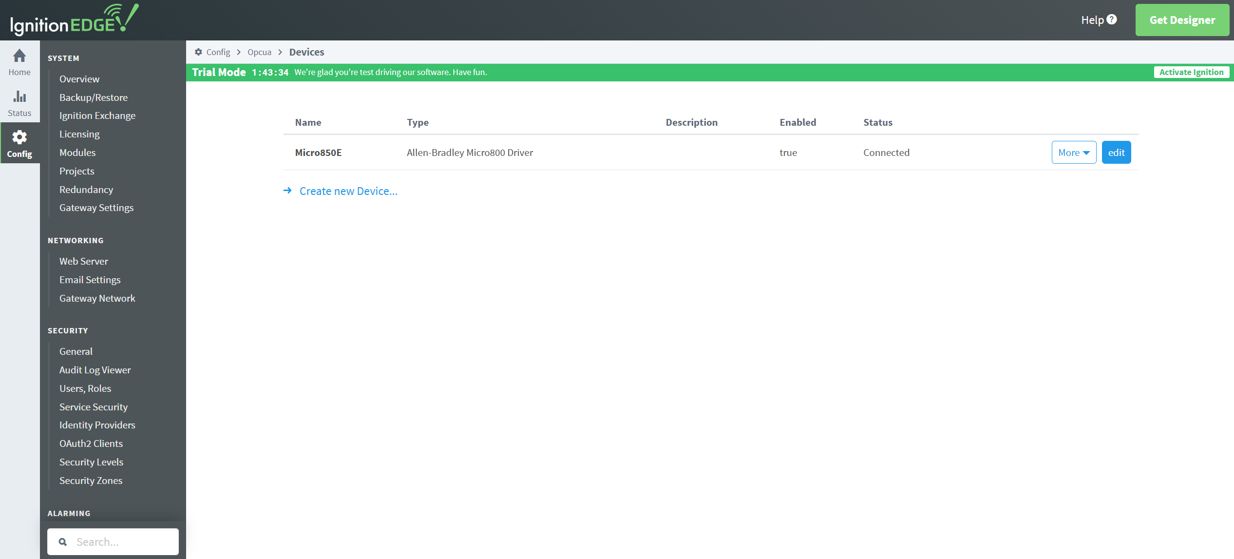
Figure 16: Connected PLC.
8. Create some tags to be able to test the system. For this, the Ignition designer needs to be installed on your programming computer. Choose Get Designer at the top right corner of the gateway web page to download the Designer launcher and install it.
9. When it is installed, choose Add Designer and open the Ignition Edge Designer session. You may need to manually add the host IP and port.
10. On the Tag Browser, at the bottom left area of the Designer, choose Browse devices and choose your PLC.
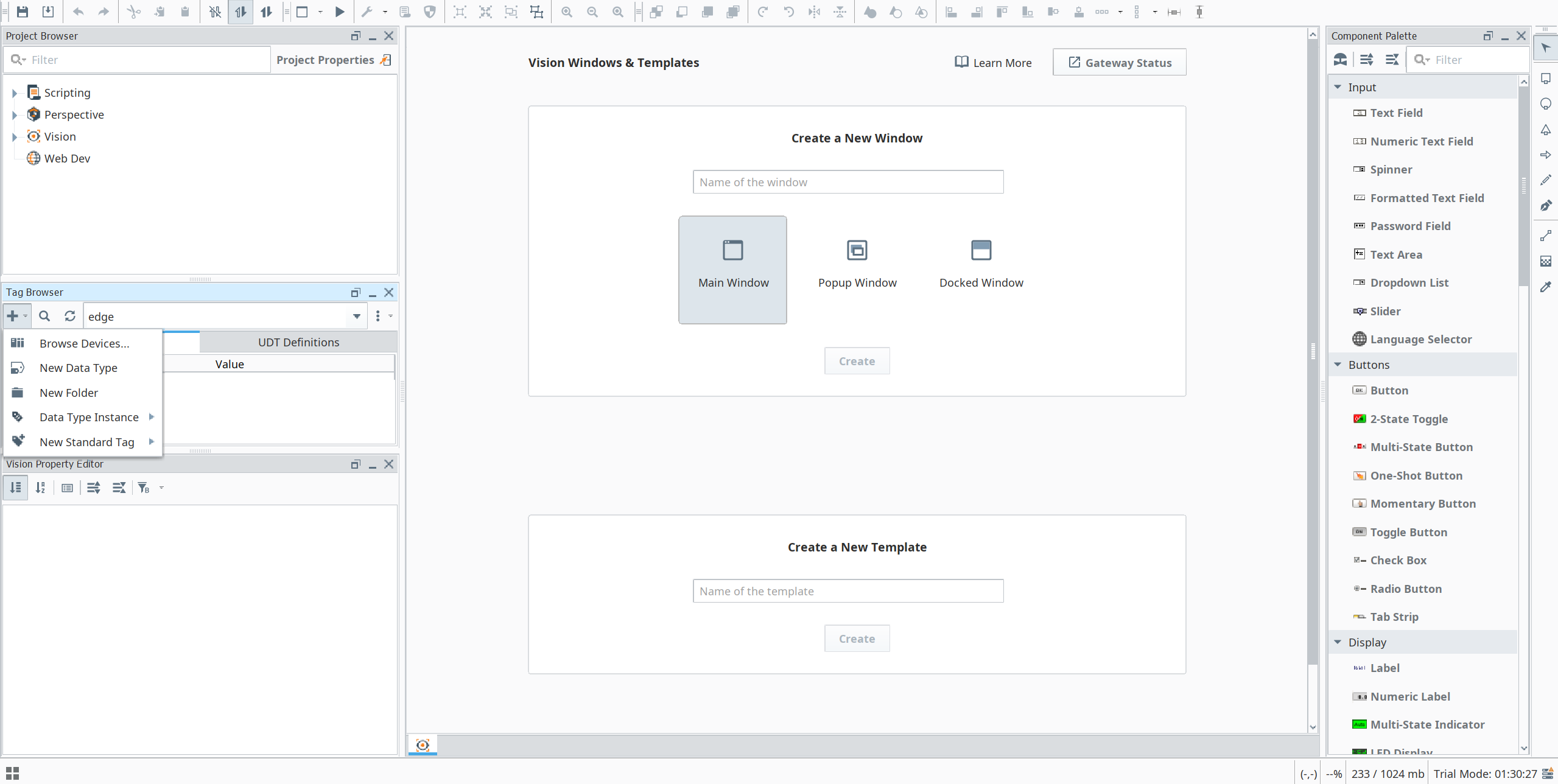
Figure 17: Ignition Designer.
11. Choose some PLC tags of interest and add them to the tag browser table.
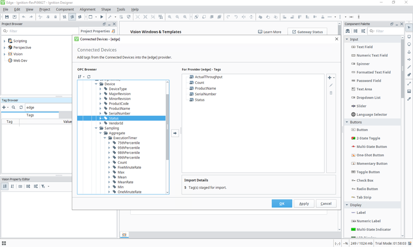
Figure 18: Tag selection.
12. Now you can check that data is starting to flow from the PLC to the Edge Gateway. The Value column updates with real-time values.
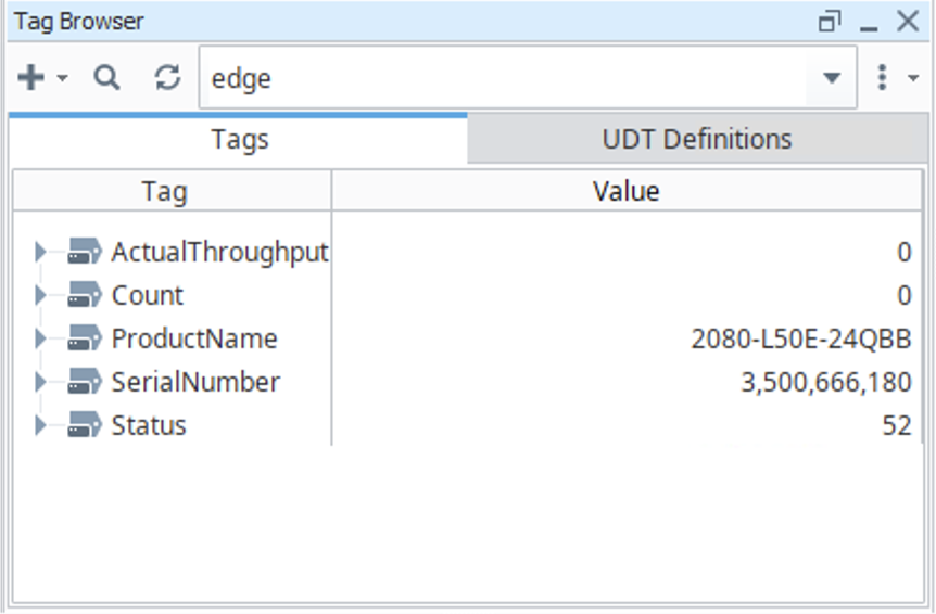
Figure 19: PLC device tags.
13. With data flowing into the edge tag system from the PLC, you can set up the central gateway on AWS.
Step 5. Ignition on AWS set up
Now you can set up a cloud hosted Ignition central gateway.
5.1 Provision Amazon EC2 on AWS and install Ignition
1. Navigate to Amazon EC2 on AWS and choose Launch instance.
2. Give the EC2 instance a name and choose Ubuntu as the operating system.
3. Choose t2.medium for the instance type and create a new key pair.
4. Under Network settings, choose the VPC and subnet you already created.
5. Enable Auto-assign public IP.
6. Choose Create security group.
7. Leave the remaining options as default and choose Launch instance.
8. Navigate to the newly created security group and choose Edit inbound rules.
9. Add a rule of Type “Custom TCP”, Port range “8088”, and Source “My IP”. This allows you to connect to the cloud Ignition interface. Add another rule for port 8060 for the Gateway Network (next section).
10. Note the Amazon EC2 Public IPv4 address on the instance summary page. This is the address for connecting to the cloud Ignition instance later.
11. Download Ignition – Linux Installer 64-bit from the Inductive Automation website.
12. Securely transfer this file to the instance.
13. Connect to the EC2 instance with an SSH client.
14. You should be able to ping the RUT956 and the RevPi IP addresses from the Amazon EC2 terminal now.
15. Install Ignition by using the following commands and following the prompts.
$ chmod +x ignition-8.1.48-linux-64-installer.run
$ ./ignition-8.1.48-linux-64-installer.run
16. In a browser, enter the public IP address of the instance and port 8088, for example http://11.22.33.44.:8088. Install Standard Edition and set the username and password. Choose the start from scratch option.
5.2 Set up the Gateway Network
Now you can connect the Ignition instances using the Gateway Network. You can alternatively connect edge to cloud with an MQTT topology. The connection needs to be configured on each gateway. It is a good practice to set up the connections in the node that is closer to the edge of the network, so that the connection is approved at the AWS level of the architecture. Make sure that the default port 8060 is allowed to establish communications between the edge and AWS Ignition Gateways in any firewalls involved.
1. Navigate to the Gateway Network config option on the Ignition Edge instance.
2. Leave the default settings and go to the Outgoing Connections tab. Choose to create a new Outgoing Gateway Connection. For Host, enter the Ignition Amazon EC2 Private IPv4 address. Choose Create New Outgoing Gateway Connection.
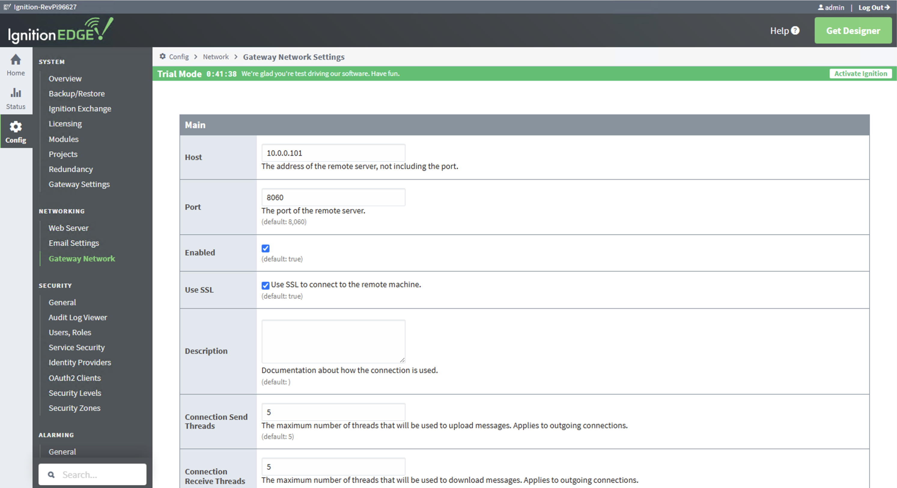
Figure 20: Establishing the gateway network connection.
3. Choose approve to accept the Remote Certificate in the AWS Gateway configuration page.
4. After a few seconds, the new connection should appear in the Incoming Connections list with PendingApproval as its Security status. Choose More and approve to enable the connection.
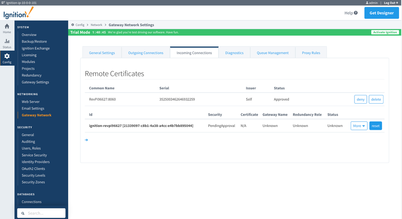
Figure 21: Approving the incoming connection.
5. The connection shows Approved in the Security field, and the Status shows Running. This means both gateways are connected, and data can flow between Edge Gateway and AWS Gateway. To test that the data is flowing through the system, create a remote tag provider so that you can obtain the real-time tag values from the edge.
6. Go to Config > Tags > Realtime Tag Providers in the AWS Ignition Gateway and create a new Realtime Tag Provider.
7. Choose Remote Tag Provider and choose Next.
8. Choose the Ignition Edge Gateway from the list and choose Next.
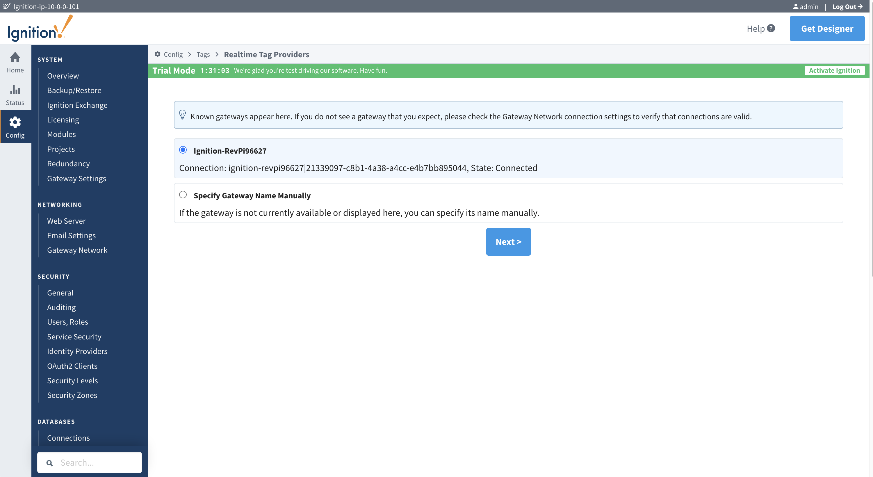
Figure 22: Selecting the gateway.
9. Choose edge as the tag provider name to connect to.
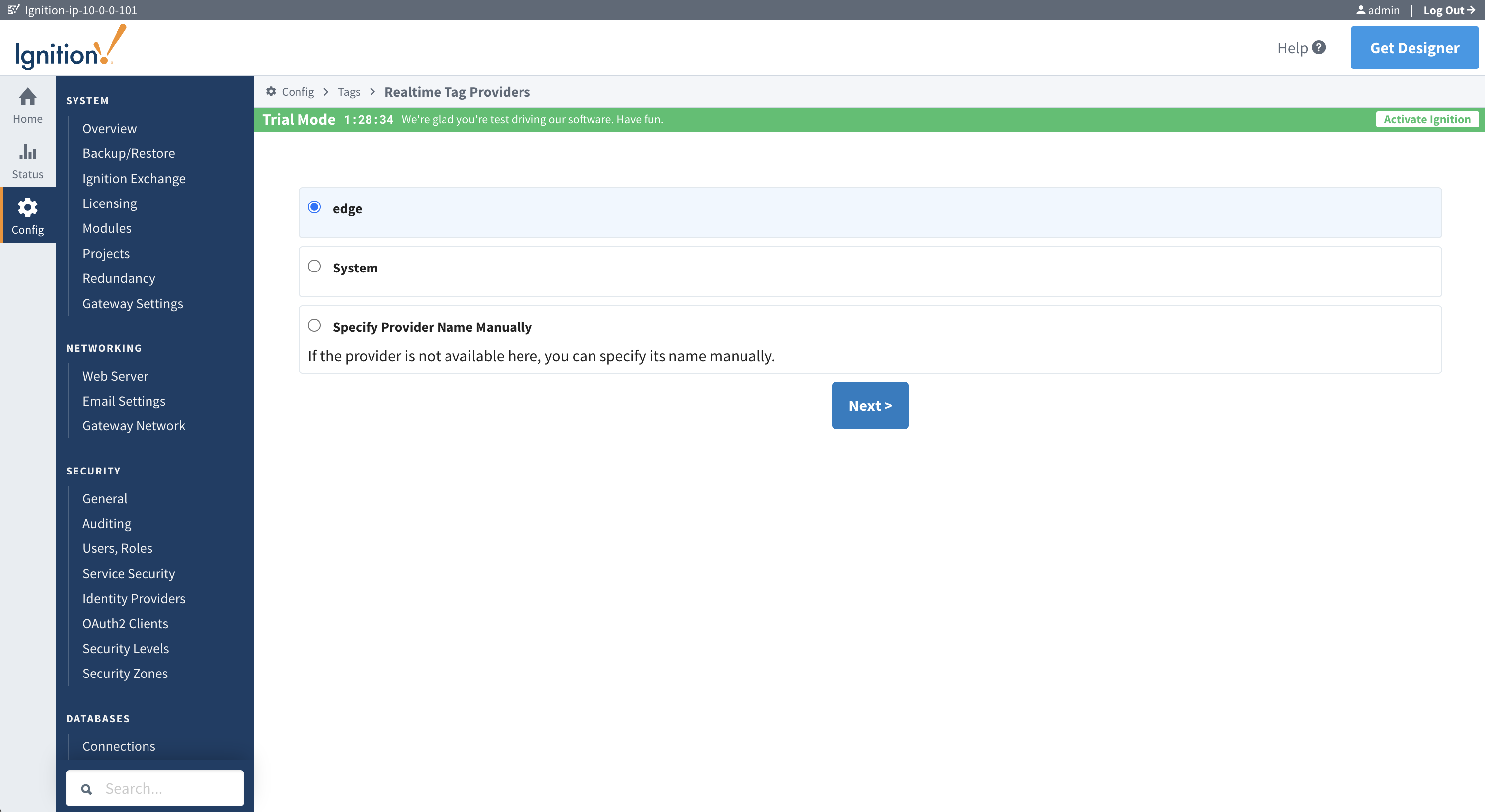
Figure 23: Selecting the tag provider.
10. Give the remote provider a name and choose Create New Realtime Tag Provider.
11. Now you have a remote real-time tag provider bringing tags from the edge into your Ignition Central Gateway installed in AWS. To test the data coming through, you can launch a Designer session to the Ignition Gateway in AWS and look at the tags created in the Tag Browser.
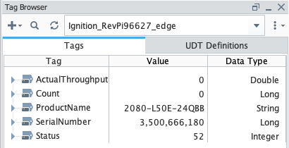
Figure 24: PLC data from the remote edge.
12. When the gateway network connection is established, you can start sharing tags, alarms, notification pipelines, history providers, etc. More information about the power of the gateway network can be found in the Ignition manual.
Conclusion
In this post, we have created a hardware system that enables bi-directional, encrypted communications between a remote PLC and the AWS cloud. You can use the AWS Site-to-Site VPN connectivity of the RUT956 as the basis for a more complex operational solution that uses Ignition. Follow the links in the Further reading section to learn more about OT and networking possibilities.
There are other cybersecurity measures you should consider for a production system based on this design. Expand and harden the cloud architecture, then review it with an experienced cybersecurity specialist in accordance with the Security Pillar of AWS Well-Architected. You may decide to move the Ignition instance to a private VPC accessed through AWS Client VPN. Deploy security applications, remote access solutions, and next generation firewalls from the AWS Marketplace. Understand your unique security risks and develop threat models.
If you use this design in an interesting application, then we would love to hear about it. Good luck!
Further reading
Whitepaper: Secure Your Global OT/IT Networks with AWS Cloud WAN
Whitepaper: Ignition + AWS Guide: Edge-to-Cloud Resiliency & Disaster Recovery
Workshop: SCADA Disaster Recovery on AWS for Inductive Automation’s Ignition
Blog: How SGN extended isolated networks to AWS using AWS Transit Gateway
Blog: Simplify global hybrid connectivity with AWS Cloud WAN and AWS Direct Connect integration
Blog: Build Global SD-WANs with AWS Cloud WAN Tunnel-less Connect