Networking & Content Delivery
Centralized ingress inspection architecture in AWS Cloud WAN
In this post, we explore architectural patterns for implementing centralized internet ingress with inspection using AWS Cloud WAN. We examine different design considerations and integration strategies with centralized internet egress while walking through practical examples and deployment scenarios. We demonstrate how to use the AWS Cloud WAN core networking capabilities alongside other AWS networking services such as AWS Network Firewall, Application Load Balancers (ALB), Network Load Balancers (NLB) to build a robust and secure internet ingress architecture that meets your organization’s specific requirements.
AWS Cloud WAN is a managed wide area networking service that enables organizations to build, manage, and monitor a unified global network that privately connects resources running across multiple Amazon Web Services (AWS) Regions and on-premises locations. It streamlines the traditionally complex task of building and operating a global network by providing a central dashboard to define network policies, automate routing, and visualize network health and performance across your entire infrastructure.
Organizations often implement centralized network architectures with inspection capabilities to maintain consistent security controls and compliance requirements across their distributed applications. Security teams can use this to funnel all internet-bound traffic through a central inspection point where they can implement comprehensive security measures such as intrusion detection/prevention systems (IDS/IPS), web application firewalls (WAF), and data loss prevention (DLP) tools. Organizations can centralize these security controls to reduce their attack surface, streamline security operations, and provide uniform policy enforcement across their entire cloud footprint.
Distributed deployment model for internet ingress
In a distributed ingress deployment model, you configure each application Amazon Virtual Private Cloud (Amazon VPC) to receive traffic directly from the internet through its own internet gateway, with firewall appliances or Network Firewall endpoints deployed locally for inspection.
Pros of distributed deployment model
- Simplified traffic flow: Direct internet-to-application routing reduces latency and network hops.
- Isolated failure domains: Issues in one VPC don’t impact other applications
- Independent scaling: Each application can scale its ingress capacity independently
Cons of distributed deployment model
- Operational complexity: Managing dedicated firewall infrastructure in each VPC multiplies operational overhead and increases the risk of configuration drift
- Policy management: Maintaining consistent security policies across multiple distributed firewall instances creates significant operational burden
- Cost inefficiency: Each VPC requires duplicate resources (firewalls, gateways, endpoints), leading to higher overall costs as you scale
There are scenarios where you can’t use distributed architectures. For example, you have a policy that doesn’t permit an internet gateway in your application VPCs, or your organization needs all traffic to/from internet traverse through the AWS Cloud WAN. To address these security requirements, you can use a centralized architecture that provides consistent security controls while reducing operational overhead. Furthermore, you can use this centralized approach to control internet access by centrally restricting the internet gateway associations to specific VPCs.
For a detailed comparison of distributed versus centralized firewall deployment patterns, see Design your firewall deployment for internet ingress traffic flows.
Centralized internet ingress architectures using AWS Cloud WAN
In the centralized ingress deployment model, all traffic into your AWS network comes through an Ingress VPC hosting the security appliances. From there, it gets forwarded to the target application in another VPC through AWS Cloud WAN.
In this section, we dive deep into two common centralized internet ingress architectures using AWS Cloud WAN. We examine their design patterns and provide detailed packet flow analysis to help you understand how traffic moves through these configurations:
- Scenario 1: Ingress VPC and Application VPCs in the same Region
- Scenario 2: Ingress VPC and Application VPCs in different AWS Regions
Scenario 1: Ingress VPC and application VPCs in the same Region
In our first scenario, we explore a deployment where both the Ingress VPC and Application VPCs reside within the same Region. This pattern is ideal for organizations needing streamlined management and lower latency between security controls and applications. We analyze how packets traverse through security appliances and reach their intended destinations while maintaining compliance with security policies.
Figure 1 shows the centralized ingress architecture with dedicated Ingress and Application VPCs per Region. The AWS Cloud WAN core network uses two segments:
- Ingress Segment: The Ingress VPC (with internet gateway, Network Firewall endpoints, and ALB) connects to the Ingress segment.
- Application Segment: The Application VPC (hosting workloads without internet gateway) connects to the Application segment.
Although this post demonstrates centralized inspection using Network Firewall, the architectural concepts and traffic flow patterns remain applicable for Gateway Load Balancer (GWLB) deployments with third-party firewall solutions.
In centralized internet ingress architecture, a load balancer (NLB/ALB) is required in the Ingress VPC because AWS Cloud WAN operates at Layer 3 and cannot perform the Layer 7 (HTTP/HTTPS) or Layer 4 (TCP/UDP) load balancing and application processing that internet-facing applications require. The architecture flow requires internet traffic to first hit the load balancer in the Ingress VPC (which has the internet gateway), then route through AWS Cloud WAN to private Application VPCs.
For your dual-stack applications, you can configure your load balancers in Ingress VPC to receive both IPv4 and IPv6 traffic from internet clients. However, note that the targets in Application VPCs need to be IPv4 addresses only. This is because only the IP-type targets are supported for IPv6 targets and the IPv6 addresses need to be from the same VPC IPv6 space as the load balancer. You can’t point to IPv6 addresses from peered VPCs or from networks connected through AWS Transit Gateway, AWS Cloud WAN, or AWS Direct Connect. For more information, refer to the Scaling the dual-stack network design in AWS documentation.
Architecture
The core network policy is configured to do the following:
- Enable sharing between Ingress and Application segments for bidirectional traffic flow
Note: While this blog uses a single Application segment, real-world deployments typically have multiple segments representing different environments (Production, Development, Staging). Segment sharing enables the Ingress segment to provide centralized inspection for all these isolated segments.
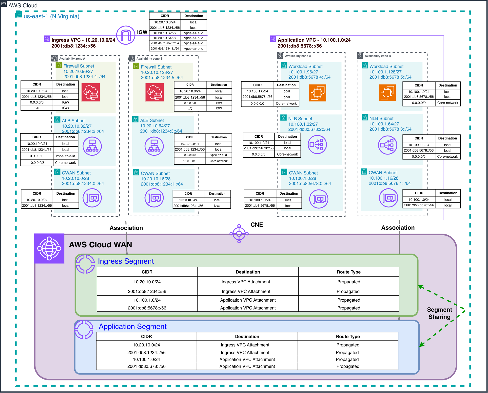
Figure 1: Ingress and Application VPCs in the same Region
This configuration makes sure of centralized traffic inspection while maintaining strict workload isolation between different environments.
Packet walkthrough
In this section we review the packet flow depicted in Figure 2.
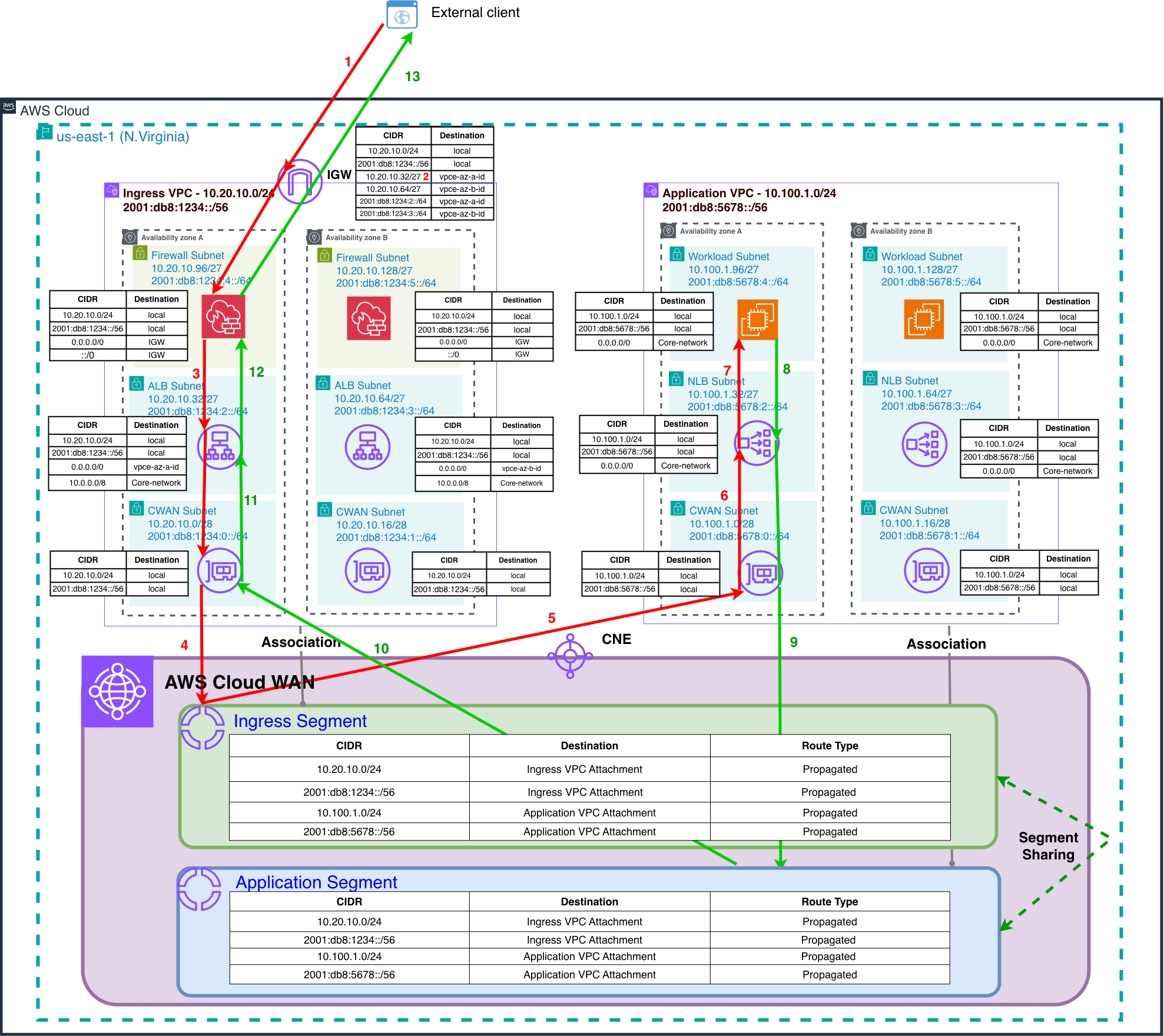
Figure 2: Packet flow when Ingress and Application VPCs are in the same Region
Forward traffic flow
- Client on the internet resolves domain name of the ALB and gets a public IPv4 address (or IPv6 Global Unicast Address) and connects to the node in the AZ-A.
- The internet gateway uses a gateway route table to perform ingress routing, directing packets to the Network Firewall endpoint deployed in AZ-A within the Firewall subnets.
- Following security policy evaluation, the firewall appliance makes an allow or deny decision for the traffic based on the configured security policies. Then, allowed traffic is forwarded from the firewall endpoint to the ALB in the Public subnets.
- The ALB performs traffic distribution to the IP-based target groups. This traffic is forwarded through the AWS Cloud WAN attachment into the designated Ingress Segment of the AWS Cloud WAN.
- AWS Cloud WAN routes the traffic from the Ingres Segment to the Application VPC.
- Traffic enters the target Application VPC and is handled by an internal Network Load Balancer (NLB) in the NLB subnets. The internet-facing ALB must use IP as the target type to register the static IP addresses of the internal NLB.
- The NLB runs network-layer load balancing and distributes traffic to backend application targets hosted on Amazon Elastic Compute Cloud (Amazon EC2) instances.
Return traffic flow
- The EC2 instance in the Application VPC responds to the NLB.
- The NLB processes the return traffic and forwards responses back to the AWS Cloud WAN Application Segment.
- AWS Cloud WAN routes the return packets from the Application Segment back to the Ingress VPC.
- Return traffic enters the Ingress VPC through the AWS Cloud WAN attachment and is forwarded to the ALB.
- The ALB processes the return traffic and forwards it to the Network Firewall endpoint in the same AZ from which the original traffic originated.
- Following firewall validation of the return traffic, packets are routed through the internet gateway back to the originating internet client.
This architecture provides a single point of enforcement per AWS Region, reducing duplication and streamlining policy management. AWS Cloud WAN routes inspected traffic to the appropriate Application VPCs while maintaining isolation between different network segments and environments.
Multi-Region ingress extension
This architecture can be extended to support multiple inspection Regions by deploying dedicated Ingress VPCs across different Regions. As shown in Figure 3, each Regional Ingress VPC maintains its own internet gateway and Network Firewall endpoints. This provides geographically distributed inspection capabilities while applications remain centralized or distributed according to business requirements. This approach provides Regional redundancy, reduced latency for global users, and compliance with data sovereignty requirements while maintaining consistent security posture across all entry points.
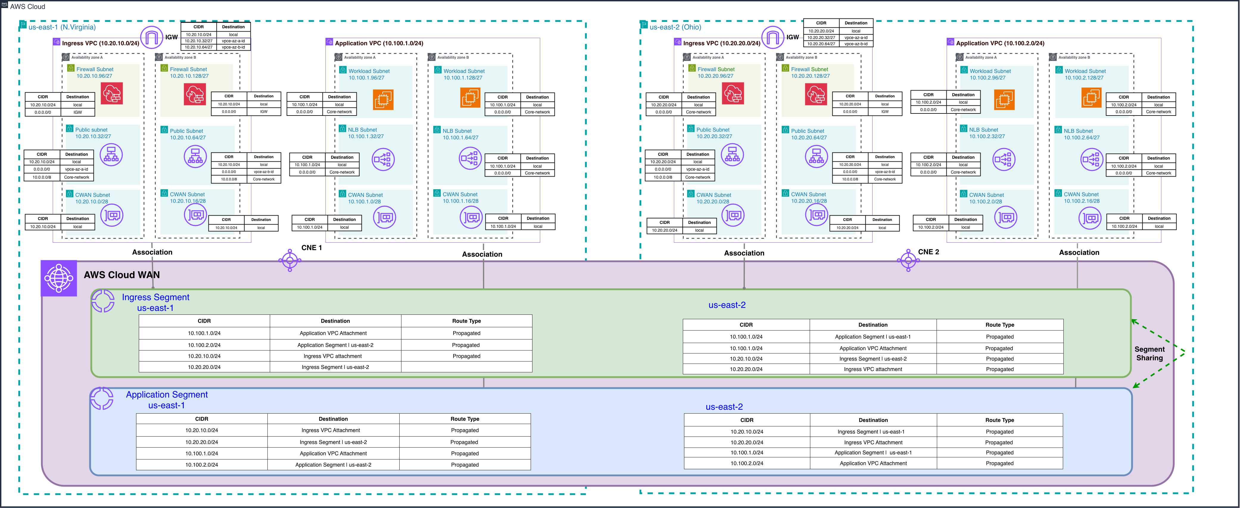
Figure 3: Multi-Region ingress extension
Scenario 2: Ingress and Application VPCs in different AWS Regions
In this scenario, AWS Cloud WAN’s global backbone supports routing traffic from a centralized Ingress VPC in one Region to Application VPCs deployed in different Regions. Some organizations may find this approach attractive to consolidate ingress infrastructure, reduce costs, or simplify security policy management across a multi-Region footprint, accepting a trade-off of slightly higher cross-Region latency. While this pattern is technically feasible, it is worth considering the resilience implications before adopting it for production workloads. Having a single regional entry point means that a regional disruption or misconfiguration in the Ingress VPC could increase the scope of impact across applications in other Regions. Organizations should carefully weigh these considerations against their specific cost, operational, and latency requirements.
For multi-Region deployments where resilience and performance are priorities, we recommend deploying dedicated Ingress VPCs alongside their respective Application VPCs in each Region, as described in the “Multi-region ingress extension” section. This approach provides regional redundancy, lower latency for global users, and a reduced scope of impact while maintaining consistent security controls across your global network.
Architecture
Figure 4 illustrates this pattern, with Application VPCs deployed in us-east-1 (N. Virginia) and us-east-2 (Ohio) Regions, while the centralized Ingress VPC remains in us-east-1 (N. Virginia). The traffic flow follows the same 13-step process described in Scenario 1, with AWS Cloud WAN’s global backbone handling the cross-Region routing between the Ingress and Application VPCs. The core network policy and segment configurations remain identical to Scenario 1.
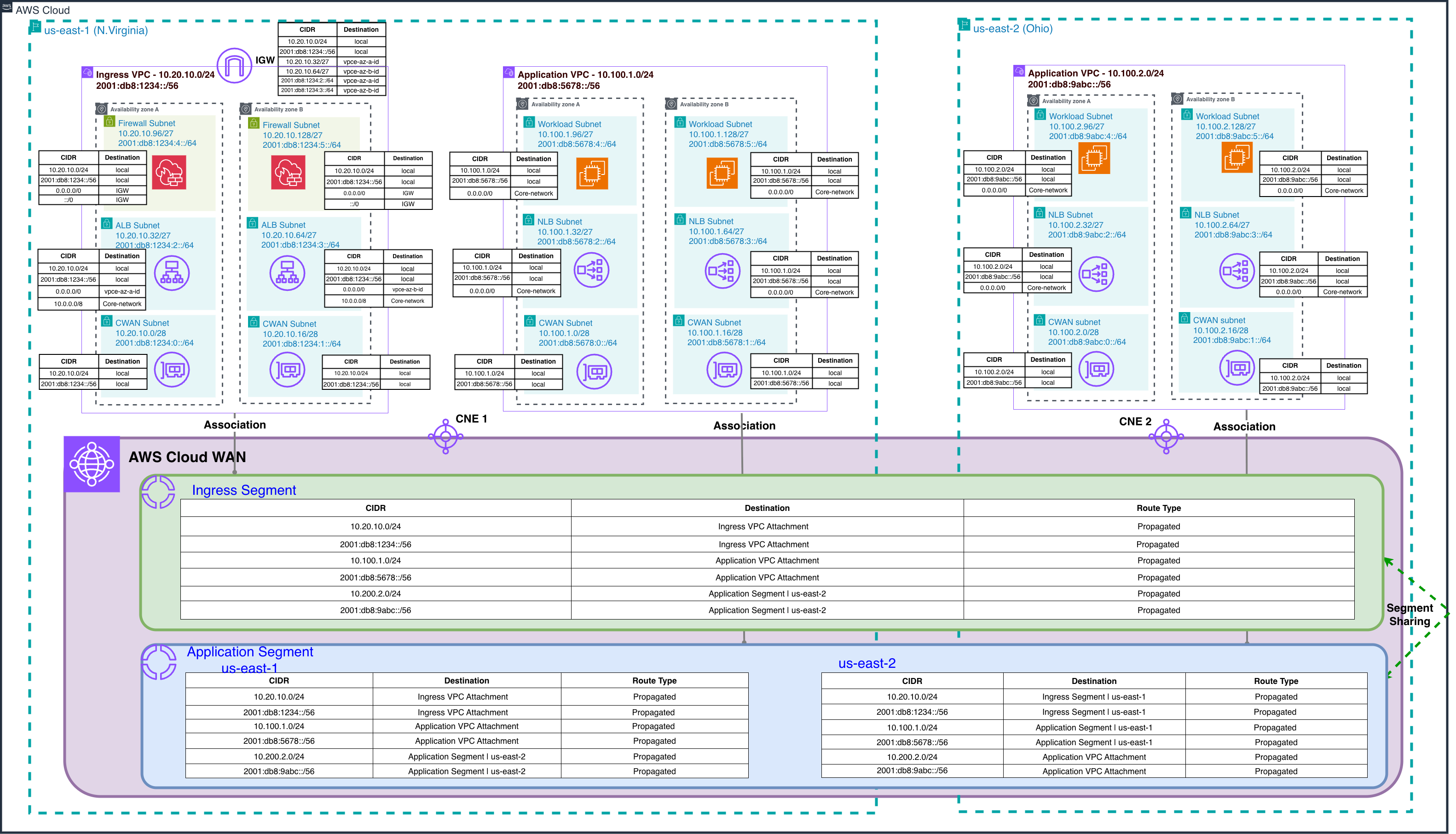
Figure 4: Ingress and Application VPCs in the different Regions
Integrating centralized ingress inspection and egress inspection using AWS Cloud WAN
Organizations committed to robust network security need complete visibility and control over bidirectional traffic flows. Although the previous sections focused on centralized ingress inspection using dedicated Ingress VPCs with Network Firewall, many customers also need to inspect and control egress traffic leaving their AWS environment. AWS Cloud WAN provides this integration by using service insertion capabilities for egress traffic while supporting traditional inspection methods for ingress traffic, creating a unified security architecture.
Integrated architecture overview
Figure 5 shows comprehensive traffic inspection through two specialized methodologies. For ingress traffic, dedicated Ingress VPCs with Network Firewall endpoints inspect internet traffic arriving through the internet gateway before routing it to Application VPCs through the AWS Cloud WAN core network. For egress traffic, the AWS Cloud WAN service insertion functionality employs send-to segment actions to automatically direct outbound traffic from Application VPCs through centralized inspection points before reaching the internet or on-premises destinations.
Note
The GWLB endpoints shown in the Egress VPC (Figure 5) provide centralized internet egress for both IPv4 and IPv6 traffic. IPv6 prefixes are local to their assigned VPC, thus IPv6 addresses must be translated in the centralized Egress VPC for internet-bound traffic. This necessitates third-party appliances behind the GWLB to support either NAT66 (Stateful IPv6-to-IPv6 Network Address Translation) or NPTv6 (Stateless one-to-one IPv6 prefix translation). As of this writing, Network Firewall doesn’t support NAT66/NPTv6. This architecture supports internet egress for resources using Global Unicast Addresses (GUA), IPv6 Unique Local Addresses (ULA), or private GUA IPv6 addresses. For more details, go to Design and build IPv6 internet inspection architectures on AWS.
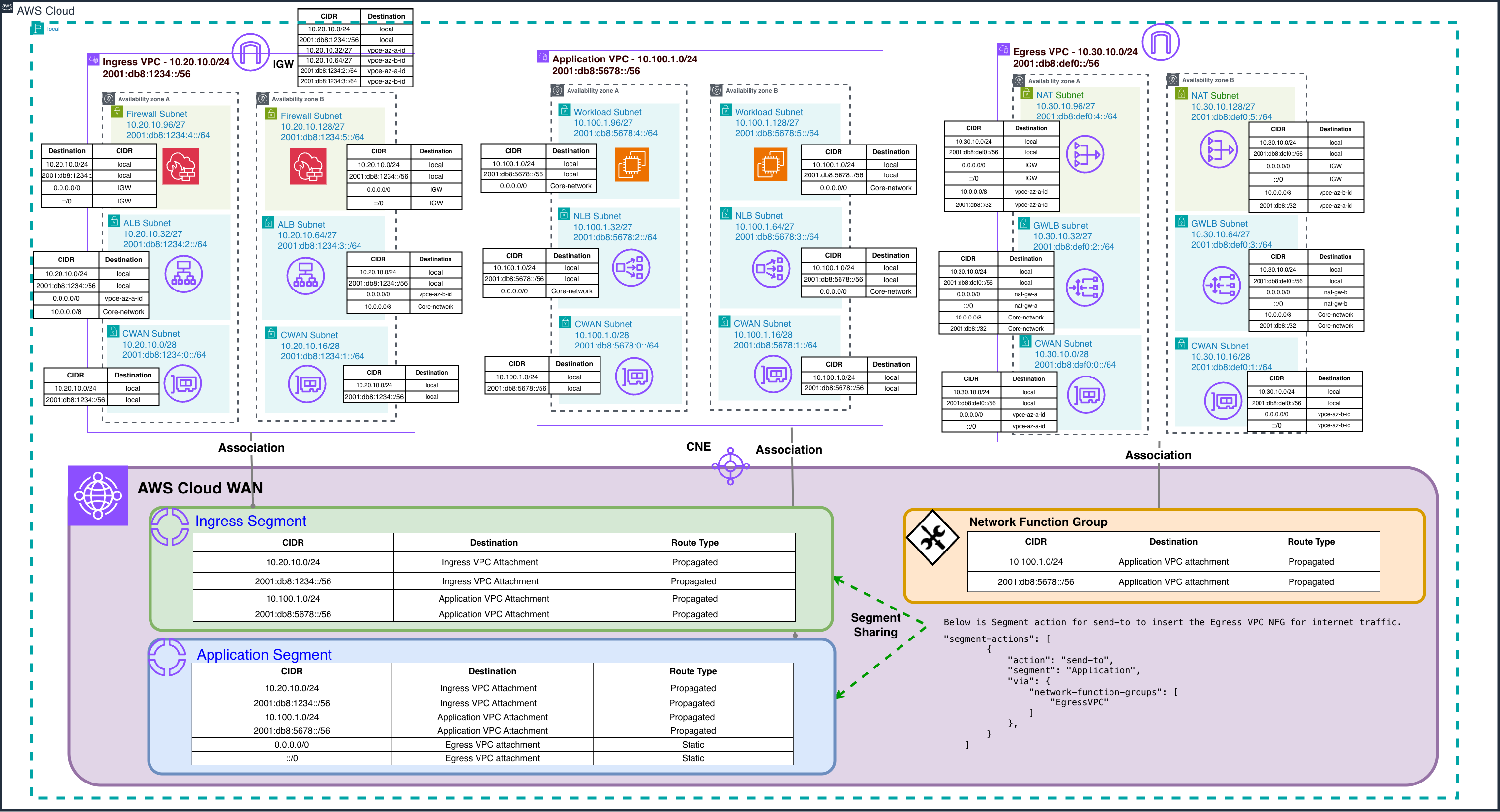
Figure 5: Integrated centralized internet ingress and egress inspection architecture using AWS Cloud WA
This solution maximizes infrastructure investment by using a single AWS Cloud WAN core network for both traffic directions, with enhanced segment policies and send-to actions for egress inspection. The integrated approach provides significant operational benefits through unified management interfaces. Therefore, network administrators can configure segment policies, monitor traffic flows, and troubleshoot connectivity issues using consistent AWS Cloud WAN tools. This consolidation eliminates the complexity of managing separate networking infrastructures while maintaining centralized visibility across all organizational traffic flows.
Considerations
- Service insertion scope and architectural planning: AWS Cloud WAN service insertion supports centralized East-West traffic inspection through the
send-viaaction and centralized internet egress traffic inspection through thesend-toaction. For internet ingress scenarios, organizations can implement layered inspection architectures: performing initial threat filtering within a dedicated Ingress VPC using services like AWS Network Firewall (which preserves original client IP visibility), followed by optional Cloud WAN service insertion for East-West segmentation policies as traffic routes from Ingress to Application segments. This blog demonstrates a single-layer ingress inspection approach where traffic is inspected at the VPC boundary before Cloud WAN routing, avoiding double inspection overhead while maintaining security posture. - Load balancing considerations:
- Cross-VPC load balancing:
- When using an NLB with an ALB as its target, both load balancers must reside in the same VPC and AWS account. This limitation means that you can’t configure an ALB in your Application VPC as a target for an NLB in your Ingress VPC. This constraint should be carefully considered when designing your AWS Cloud WAN architecture. However, NLBs support static IP addresses per AZ, thus you can configure an NLB in your Application VPC as a target (using IP as target) for an ALB in your Ingress VPC.
- Make sure that the ALB’s target group is configured with the NLB’s private IP addresses rather than its DNS name, because AWS Cloud WAN needs IP-based routing. We use ALB in front of NLB in this blog to leverage Layer 7 capabilities like path-based routing and SSL termination, though you could alternatively use NLB in front of NLB if your use case requires pure Layer 4 load balancing with static IP requirements.
- Client IP preservation and visibility: For NLB deployments in the Ingress VPC with targets registered in a different VPC connected through AWS Cloud WAN, client IP preservation cannot be enabled. This is because client IP preservation requires the target to be in the same VPC as the load balancer or in a peered VPC in the same Region. In this configuration, the NLB’s private IP address is used as the source IP for traffic forwarded to targets. ALBs do not preserve client IP data by design, and the original client IP is not visible in the IP packet header itself. Applications needing original client IP data can obtain this information through X-Forwarded-For headers (when using ALB) or Proxy Protocol v2 (when using NLB) without disrupting the symmetric traffic architecture.
- Cross-VPC load balancing:
- Architectural complexity and impact radius: When you implement centralized ingress inspection, you’re introducing more architectural complexity when compared to distributed models. This centralization increases the scope of impact where misconfiguration on centralized firewall infrastructure can affect multiple backend applications simultaneously, rather than isolating issues to individual application stacks. Weigh these operational risks against the benefits of centralized security policy management and consider implementing robust change management processes, strong coordination procedures between networking/cloud teams and application teams, comprehensive monitoring, and automated rollback capabilities.
Conclusion
In this post, we demonstrated how the AWS Cloud WAN networking capabilities can be effectively used to implement centralized internet ingress inspection patterns. We explored various architectural approaches that address common enterprise requirements for security, high availability, and scalability. Organizations can use AWS Cloud WAN alongside complementary services such as Network Firewall or GWLB to build robust and secure ingress architectures that provide consistent security controls across their global network infrastructure. Whether you’re managing a single-Region deployment or a multi-Region environment, these patterns can help you implement comprehensive security measures while maintaining operational efficiency and cost-effectiveness. To get started, refer to the AWS Cloud WAN, Network firewall, and GWLB documentation.
About the authors

Mandar Alankar
Mandar Alankar is a Senior Networking Solutions Architect at AWS. He is passionate about networking technologies and loves to innovate and help solve complex customer problems. He holds a master’s degree in Telecommunications from University of Colorado Boulder. Mandar lives in Seattle and loves travel and outdoor activities.

Vihar Kodakandla
Vihar Kodakandla is a Domain Specialist Engineer at AWS. He serves as an engineer to UOps customers, focusing on customer onboarding, building customer context, and delivering ongoing proactive mechanisms through Critical Workload Reviews. He works with customers to troubleshoot complex technical issues, identify resilience and observability opportunities across AWS networking services.