Networking & Content Delivery
Secure customer resource access in multi-tenant SaaS with Amazon VPC Lattice
In this post, we provide prescriptive guidance for building resilient and scalable multi-tenant Software-as-a-Service (SaaS) network architectures to address common challenges such as managing overlapping IP addresses, complex CIDR planning, and scaling connectivity to thousands of customers. We explore multiple architectural approaches using Amazon VPC Lattice with TCP resources, and conclude with detailed implementation guidance for each option.
SaaS providers offering multi-tenant solutions often need to access resources in their customer’s, whether on Amazon Web Services (AWS), on-premises data centers or on other cloud platforms. These customer-managed resources, such as databases, Enterprise-Resource-Planning (ERP) systems, event subscribers, or web-hook endpoints, need to be integrated into the SaaS provider’s service, but remain hosted and controlled within the customer’s environment. For example, consider healthcare application that needs to access hospital-specific patient databases. Figure 1 depicts this challenge.
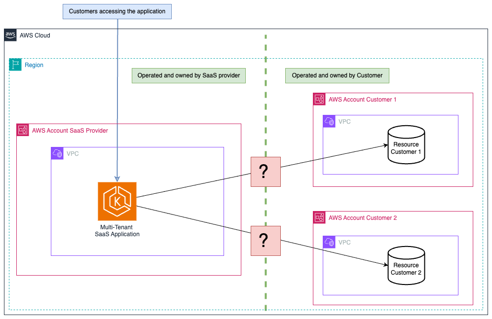 Figure 1: Traditional multi-tenant architectures face challenges when accessing customer resources across account boundaries. The access layer is abstracted for clarity.
Amazon VPC Lattice allows secure communication between applications and their components in modern distributed architectures. This enables organizations to connect and manage services across multiple accounts and VPCs without complex networking configurations. Resource Gateways extend the VPC Lattice capabilities by allowing direct connectivity to resources that traditionally needed complex networking setups. This feature allows SaaS providers to offer secure connectivity to customer’s resources as described in the introduction.
Before VPC Lattice support for TCP resources, SaaS providers had limited options for accessing customer resources. AWS PrivateLink requires Network load balancers, making it unsuitable for resources that don’t need or work well with load balancing, for example Kafka and HPC clusters, or distributed file systems. Network layer connectivity solutions often lead to exposing unintended network segments, since they typically connect entire VPCs or subnets rather than isolating access to specific endpoints. Internet-based access implies additional security considerations and typically requires enhanced security controls and tools, such as web application firewalls, to effectively mitigate threats.
Choosing the right architecture option for your use case
In the following sections we explore several decision points that help you implement VPC Lattice resource gateways effectively. Building on the insights from our previous post about PrivateLink support for VPC resources and its implications for SaaS providers, we guide you through these key architectural decisions.
1. PrivateLink or VPC Lattice with TCP resources?
When using PrivateLink with TCP resources and resource gateways, the SaaS provider deploys a VPC endpoint in its VPC for each resource to which it needs to connect. The number of endpoints can quickly become difficult to manage with multiple tenants and resources, leading also to cost increase. We recommend that you use PrivateLink for single tenant environments or multi-tenant environments with a small number of customers and resources. Figure 2 demonstrates this multi-tenant setup where customer resources are accessed through PrivateLink VPC resource endpoints.
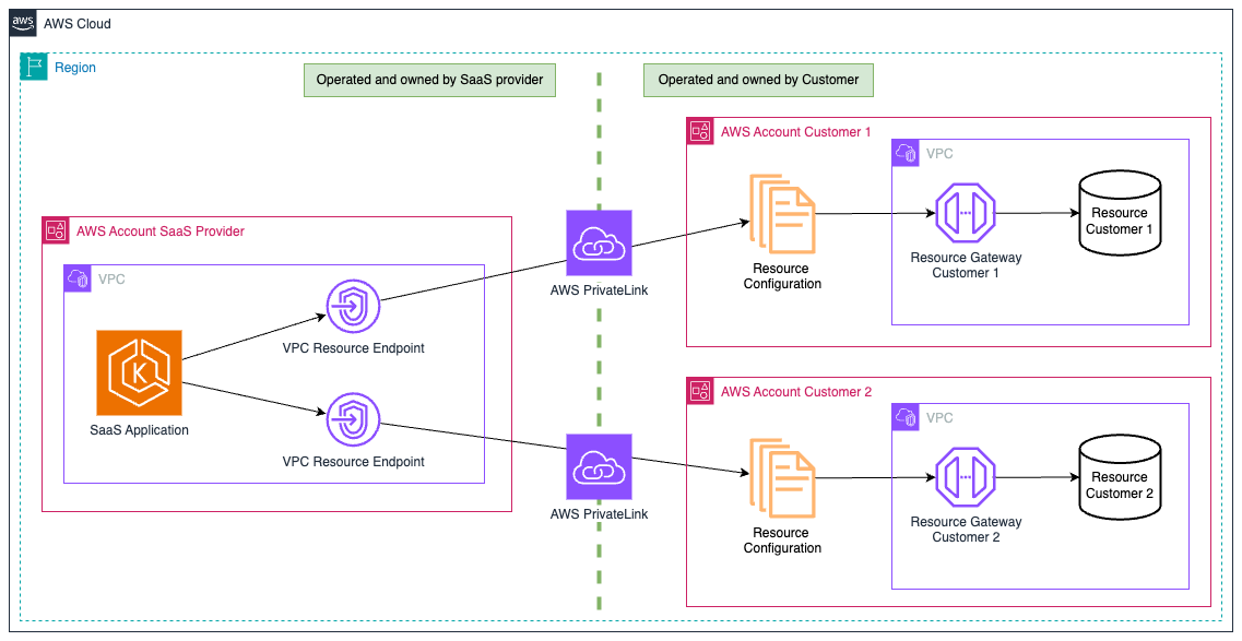 Figure 2: Using PrivateLink with Resource Gateways requires separate VPC resource endpoints for each customer resource, making it suitable primarily for small-scale deployments.
You can optimize and simplify your network setup using VPC Lattice and having a central place where you collect access logs and usage metrics and write security policies. With VPC Lattice, you can also choose whether to implement dedicated service networks for each tenant, or use shared service networks that serve multiple tenants. You can control access centrally in the service network, consolidate network paths, and optimize cost.
2. Choosing the right VPC Lattice service network architecture
The following two sections outline the different VPC Lattice service network architectures: A – one service network per tenant, and B – single shared service network
A – One Service Network per tenant
With one service network per tenant, a SaaS customer would create the service network, associate their resources, and share it with the SaaS provider. The SaaS provider can access a tenant’s resources using service network endpoints (SNEs) or service network association (SNA). This approach allows the tenant to control the operation and configuration of the service network and facilitates strict tenant isolation by maintaining each tenant within the boundaries of their own service network. Furthermore, a tenant can use the same service network to access SaaS provider services if needed, creating a bidirectional communication path. Figure 3 outlines this architecture option.
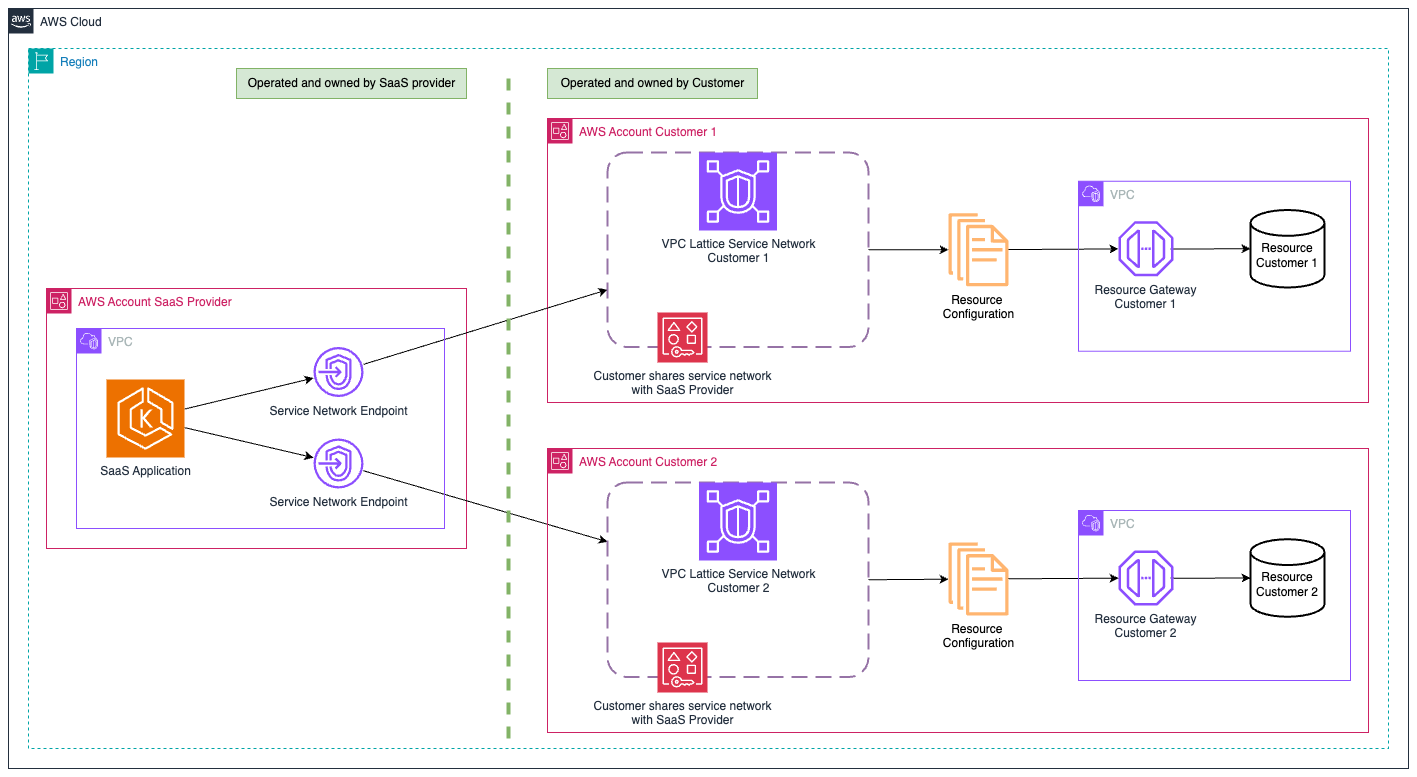 Figure 3: Customer-owned service networks offer strong isolation but add operational complexity, as each customer manages their own service network.
SaaS customers maintain complete visibility of SaaS provider access to their resources and retain full control over which resources are shared through the service network. The billing for resources and services also remains within the customer’s account, which can be beneficial for organizations that need specific cost attribution models.
For SaaS providers, access logs and metrics are distributed across multiple service networks, which requires planning for centralized monitoring and troubleshooting workflows. Each resource associated with a service network and accessed via SNEs will consume one IP address per Availability Zone in the SaaS provider VPC. The use of SNEs on the SaaS side therefore requires IP planning, and we recommend leveraging VPC segmentation and security options such as different subnets, Network Access Control Lists (NACLs) and security groups. When complemented with pod-level security groups in Amazon Elastic Kubernetes Service (Amazon EKS) environments, this creates a robust security foundation.
This architecture is well-suited for applications where customers deploy custom code and need strong access controls and resource isolation. We included an implementation guide for this architecture at the end of this post.
B – Single shared Service Network
SaaS providers can create a VPC Lattice service network in their account and associate resource configurations shared by multiple tenants with it. Tenants share their resource configurations with the SaaS provider and thus grant access to their resources. Take into consideration network isolation: while tenants cannot directly access other tenant resources from their own VPCs or networks, any tenant workload deployed within the SaaS provider VPC, for instance on a Pod within your Kubernetes cluster, could potentially connect to any attached customer resource. Robust authentication at the resource level (such as database credentials) is essential to prevent unauthorized cross-tenant access.
A key advantage of this approach is that it streamlines management by using a single service network for all tenants. As with the service network per tenant design, each resource on the service network consumes one IP address in the SaaS provider VPC per Availability Zone. For large-scale deployments with many tenants, this IP consumption should be factored into your network design and CIDR allocation strategy. Both this approach and the dedicated service network approach can scale to support many customers, but with different operational and network design considerations. Figure 4 shows a detailed diagram of this.
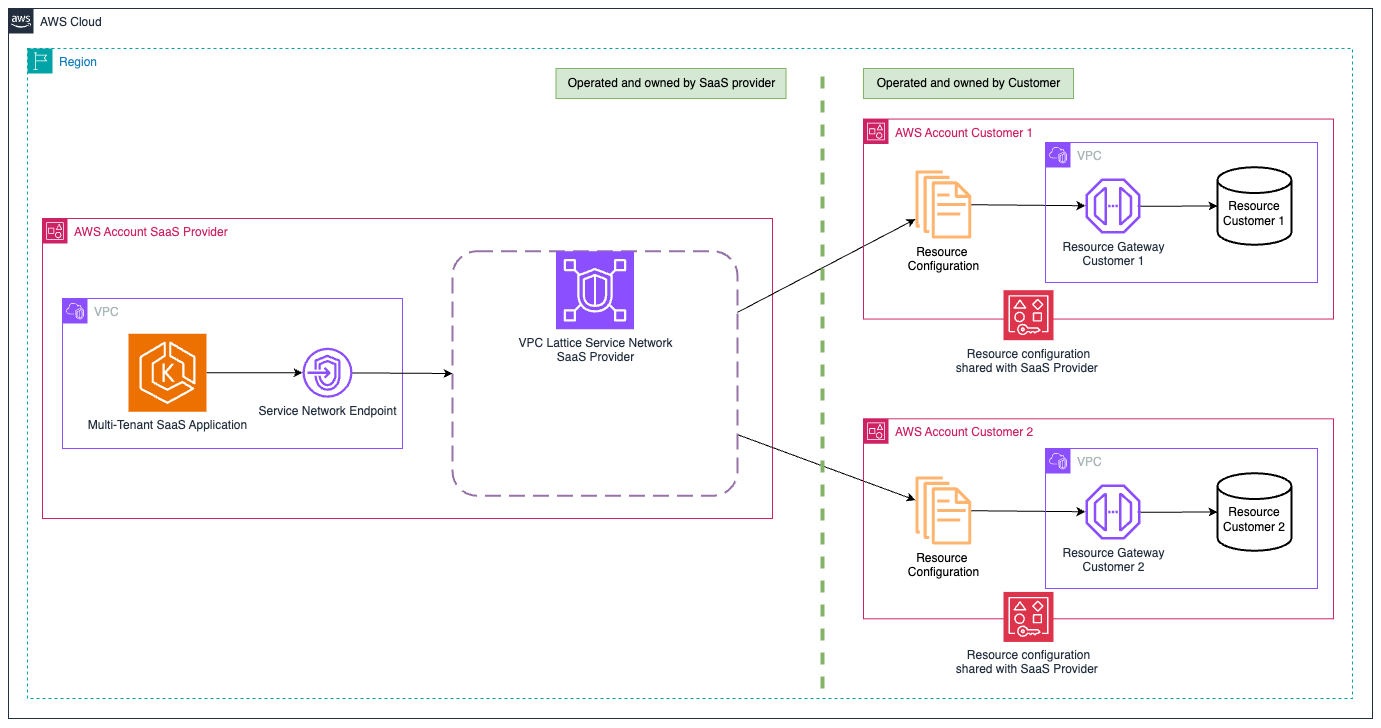 Figure 4: Using VPC Lattice with shared service networks allows scalable multi-tenant resource access.
This design ensures network security through provider-initiated connections, security groups, and customer-controlled resource sharing. However, it requires careful consideration for end-to-end security and segmentation. For environments where SaaS customers can deploy custom code or where complete network separation between tenants is needed, consider the dedicated service network approach described previously. We included an implementation guide for this architecture at the end of this post.
With this shared service network architecture, when VPC Lattice is also used to access the service, creating a separate service network for resource access traffic helps maintain clear isolation between different traffic flows. This isolation helps with monitoring, troubleshooting, and applying different security policies to inbound as opposed to outbound connections. Figure 5 shows this network configuration.
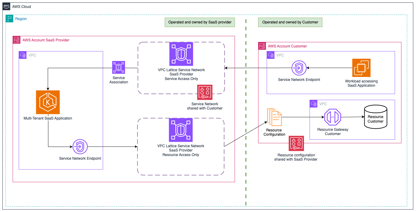 Figure 5: Shared service network architecture using VPC Lattice with a second service network for access to the SaaS application. For clarity only one customer account is depicted.
3. Choosing between service network VPC association (SNA) and SNE
You can connect a VPC to a service network using either an SNA or SNE. An SNA makes a resource associated with the service network addressable through an IP address from the AWS-owned 129.224.0.0/17 block within the VPC. This IP address is not routable outside of VPC Lattice. Only one service network can be associated to a VPC this way, which makes SNA incompatible with the dedicated service network per tenant approach.
Alternatively, SNEs allow you to connect multiple service networks to a VPC, each using one or more Elastic Network Interfaces (ENIs). Although SNEs consume IP addresses from your VPC CIDR (one per associated resource in each AWS Availability Zone (AZ), they offer the advantage of making the service network accessible from outside the VPC like any other private IP. For most multi-tenant architectures, we suggest using SNEs due to their flexibility. If you don’t have sufficient private IP addresses available in your existing VPC subnets, you can also place these SNEs in new subnets from secondary VPC CIDRs that are not routed outside of the VPC. SNAs and SNEs are free of charge. See VPC Lattice pricing page for detailed pricing dimensions and components.
Implementation
The following sections provide step-by-step implementation guidance for the previously explored architectural approaches, using AWS CloudFormation templates and AWS Command Line Interface (AWS CLI) commands.
Prerequisites
The following resources are needed to walk through the implementation steps of either solution:
- Preferably three separate AWS accounts to simulate one SaaS provider and two customers. For testing purposes, you can also use the same account for the SaaS provider and customers and skip the AWS Resource Access Manager (RAM) sharing parts in the instructions. We use three separate AWS accounts in the instructions to keep it as close as possible to real world scenarios.
- One VPC per account, with an Amazon Elastic Compute Cloud (Amazon EC2) instance in the SaaS provider VPC to simulate the service, and a resource in each customer VPC (e.g., a database or an EC2 instance listening on a TCP port) to simulate the customer resource. In this post, we use a sample TCP app listening on TCP port 1234. You can optionally use this CloudFormation template on GitHub to deploy the base infrastructure.
- AWS CLI: You need the AWS CLI installed and configured on the workstation from where you are going to follow the instructions.
- AWS CLI credentials with sufficient AWS Identity and Access Management (IAM) permissions to create and modify resources in all three accounts.
- This post assumes that us-east-1 Region is used, and your AWS CLI default AWS Region is us-east-1. If us-east-1 is not the default Region, then mention the Region explicitly while running AWS CLI commands using –region us-east-1 or make sure to consistently use your preferred AWS Region.
Implementation guide for A – one service network per tenant
Customer side:
- In the customer account, create a Resource Gateway in the VPC where the resource in question is located. While creating the Resource Gateway, choose at-least two subnets across two AZs and the Security Group with necessary rules in it.
- Create a Resource Configuration using the Resource Gateway created in previous step. The Resource Configuration should be created using the TCP port on which the resource is listening and in resource-configuration-definition, the type should be chosen as ipResource and should point to the IP address of the TCP server.
- Create a Service Network and associate the Resource Configuration created in the previous step to this Service Network.
- Create a Resource Share for this Service Network and share it with the SaaS provider account.
- Repeat these steps for other customer accounts.
SaaS provider side:
- In the SaaS provider account, accept the Resource Share Invitation from all of the customer accounts.
- Create a SNE for the service network of each customer in the SaaS provider VPC. Make sure to choose all of the AZs so that AZ mismatches between the customer and SaaS provider can be avoided. Alternatively, you can align AZs between Resource Gateways in customer VPCs and SNE in the SaaS provider VPC.
- Obtain the DNS Names assigned by the system for each customer resource and test connectivity.
- Optionally, create and associate a private hosted zone with the SaaS provider VPC and create CNAME records to point the system-generated DNS names to more user-friendly domain names.
Detailed steps for implementing this option are documented in the “Implementation Guide for A – Dedicated Service Network per Customer” section of this GItHub repository.
Implementation guide for B – single shared service network
Customer side:
- In the customer account, create a Resource Gateway in the VPC where the resource in question is located. While creating the Resource Gateway, choose at-least two subnets across two AZs and the Security Group with necessary rules in it.
- Create a Resource Configuration using the Resource Gateway created in previous step. The Resource Configuration should be created using the TCP port on which the resource is listening and in resource-configuration-definition, the type should be chosen as ipResource and should point to the IP address of the TCP server.
- Create a Resource Share for this Resource Configuration and share it with the SaaS provider account.
- Repeat these steps for other customer accounts.
SaaS provider side:
- In the SaaS provider account, accept the Resource Share Invitation from all of the customer accounts.
- Create a service network with –sharing-config enabled=false, because the default true setting prevents association of shared Resource Configurations.
- Create an SNE for the service network in the SaaS provider VPC. Make sure to choose all of the AZs so that AZ mismatches between customer and SaaS provider can be avoided. Alternatively, you can align AZs between Resource Gateways in customer VPCs and SNEs in the SaaS provider VPC.
- Obtain the DNS Names assigned by the system for each customer resource and test connectivity.
- Optionally, create and associate a private hosted zone with the SaaS provider VPC and create CNAME records to point the system-generated DNS names to more user-friendly domain names.
Detailed steps for implementing this option are documented in the “Implementation Guide for B – shared Service Network” section of this GItHub repository.
Considerations
- Make sure that the SNEs in the provider VPC are deployed in at least one AZ that matches an AZ where the customer’s resource gateway is deployed.
- In the SaaS provider side VPC, we recommend creating dedicated subnets for SNEs in each AZ. For better scalability, consider attaching a secondary CIDR blocks to your VPC specifically for these endpoints, for example, one secondary CIDR per tenant. Subnets cannot be resized after creation, so we recommend allocating generously sized subnets (such as /24 or larger) to accommodate future growth in the number of tenant resources to which you need to connect.
- To follow the implementation steps, the compute platform doesn’t matter if the Resource Gateway can connect to it. In the walk-through, we use an EC2 instance to showcase connectivity between service and resource.
- When following the implementation steps, you can skip the creation of resources in the second customer account if you want to test the solution with just one customer account first.
- Review pricing for VPC endpoints and pricing for VPC Lattice.
- Review default quotas for VPC endpoints and default quotas for VPC Lattice.
Conclusion
Amazon VPC Lattice resource gateways and resource configurations provide a powerful solution for SaaS providers to securely access customer resources in multi-tenant architectures. These technologies allow you to overcome traditional networking challenges, maintain strict security boundaries, and scale your connectivity to thousands of customers. Any of the design options we presented can be viable and depend on the specific requirements of the SaaS provider.
What they all have in common is that they work regardless of how customers are accessing the service today, be it through PrivateLink, VPC Lattice, AWS Transit Gateway, or through the internet. To learn more about exposing your SaaS application using VPC Lattice, this post serves as a good starting point
About the authors

Luca Schumann
Luca Schumann is an ISV Solutions Architect at AWS living in Germany. He holds a Master’s degree in Computer Science from the Technical University of Munich and specializes in helping independent software vendors architect and optimize their solutions using AWS networking services and Kubernetes. When he’s not architecting cloud solutions, Luca enjoys playing board games or staying active through various sports.

Vijay Menon
Vijay Menon is a Principal Solutions Architect based out of Singapore with a background in large scale networks and communications infrastructure. He enjoys learning new technologies and helping customers solve complex technical problems by providing solutions using AWS products and services. When he is not helping customers, he likes to go on long runs and spend time with family and friends.