Containers
Simplify hybrid Kubernetes networking with Amazon EKS Hybrid Nodes gateway
Organizations are increasingly adopting Amazon Elastic Kubernetes Service (Amazon EKS) and Amazon EKS Hybrid Nodes as they migrate and modernize applications across cloud and on-premises environments. Amazon EKS Hybrid Nodes enables users to integrate their on-premises and edge computing infrastructure with EKS clusters as remote nodes. This creates a unified Kubernetes management experience across distributed environments while addressing latency, compliance, and data residency requirements.
However, managing hybrid Kubernetes networking between the Amazon Virtual Private Cloud (Amazon VPC) and on-premises nodes can be challenging, often requiring network changes and coordination between Kubernetes platform teams and network infrastructure teams. A common architecture requirement for EKS Hybrid Nodes is to make on-premises pod networks routable across hybrid networks, which some customers cannot achieve due to constraints like overlapping IP addresses or complex BGP routing requirements.
We are excited to announce the general availability of the Amazon EKS Hybrid Nodes gateway, a new feature for Amazon EKS that simplifies hybrid Kubernetes networking for Amazon EKS Hybrid Nodes. The Amazon EKS Hybrid Nodes gateway automatically manages and forwards pod-to-pod traffic between the EKS VPC and on-premises environments, eliminating the need for complex networking changes to existing on-premises infrastructure. It also handles the control plane to webhook connectivity and allows AWS services such as Application Load Balancers, and Amazon Managed Service for Prometheus to seamlessly communicate with remote pods running on hybrid nodes.
EKS Hybrid Nodes gateway supports a range of use cases, including:
- Cross-environment pod-to-pod networking & cloud migrations: Organizations migrating applications to Amazon EKS while maintaining some workloads on-premises due to data residency, compliance, or infrastructure requirements. The gateway enables seamless pod-to-pod communication between cloud and on-premises without requiring network infrastructure changes.
- Webhook operations: Customers running admission controllers and policy enforcement tools (cert-manager, OPA, Kyverno) on hybrid nodes. The gateway automatically routes control plane traffic to webhook endpoints on hybrid nodes, removing the need to make on-premises pod networks routable.
- AWS service integrations: Applications with components distributed across cloud and on-premises environments that require AWS service integrations. The gateway enables VPC-to-hybrid pod connectivity, allowing consistent AWS service integrations for metrics scraping, health checks, and load balancing across hybrid environments.
By abstracting away the underlying network complexity, Amazon EKS Hybrid Nodes gateway allows users to focus on their application modernization efforts rather than managing complex hybrid networking. The EKS Hybrid Nodes gateway is open source and is available on Github.
In this post, we walk you through the architecture of Amazon EKS Hybrid Nodes gateway, deep dive into how it works, and demonstrate how it simplifies hybrid Kubernetes networking across your cloud and on-premises EKS environments.
Overview
The Amazon EKS Hybrid Nodes gateway utilizes the Cilium Container Network Interface’s (CNI) VXLAN Tunnel Endpoint (VTEP) feature. It creates VXLAN tunnels between EC2-based gateway nodes in your VPC and Cilium-managed hybrid nodes in your on-premises environment, and automatically maintains VPC route table entries to direct hybrid pod traffic to the correct gateway instance. In addition, Cilium on hybrid nodes encapsulates VPC-bound traffic and forwards it through the VXLAN tunnel to the remote VTEP device, the EKS Hybrid Nodes gateway. With this approach, users do not need to deploy additional components or configure complex BGP routing on their hybrid nodes.
To deploy Amazon EKS Hybrid Nodes gateway, you must use the AWS-maintained Cilium build, which includes a CiliumVTEPConfig CustomResourceDefinitions (CRD). The CRD enables the gateway to dynamically register itself as the remote VTEP device for hybrid nodes. You also need to configure dedicated compute capacity (an EKS Auto Mode node pool, EKS managed node group, or self-managed nodes) in the AWS Region for hosting the gateway pods.
The EKS Hybrid Nodes gateway is deployed with an active-standby pair using Kubernetes Lease-based leader election, with pod anti-affinity ensuring the two gateway pods run on separate EC2 nodes. For high availability, we recommend deploying the gateway pair across two different Availability Zones (AZs). To enable fast failover, both gateways establish VXLAN tunnels to all hybrid nodes and maintain identical tunnel states, including Forwarding Database (FDB), ARP, and route entries. Only the leader pod manages VPC route table entries and the CiliumVTEPConfig CRD, ensuring bidirectional symmetric routing through the active/leader’s VXLAN tunnel.
Architecture
For this walkthrough, we create an Amazon EKS cluster with both EKS Auto Mode and EKS Hybrid Nodes enabled. We then register on-premises machines to the cluster as hybrid nodes and install Cilium CNI with the VTEP feature enabled. We create a dedicated NodePool and NodeClass for hosting the hybrid nodes gateway. The NodeClass disables the source/destination check on the primary ENI of the gateway nodes, allowing the gateway to forward transit traffic. We then attach an IAM policy to the gateway node role, granting the gateway permission to manage VPC route table entries. Finally, we deploy the hybrid nodes gateway with an active-standby pair using a Helm chart.
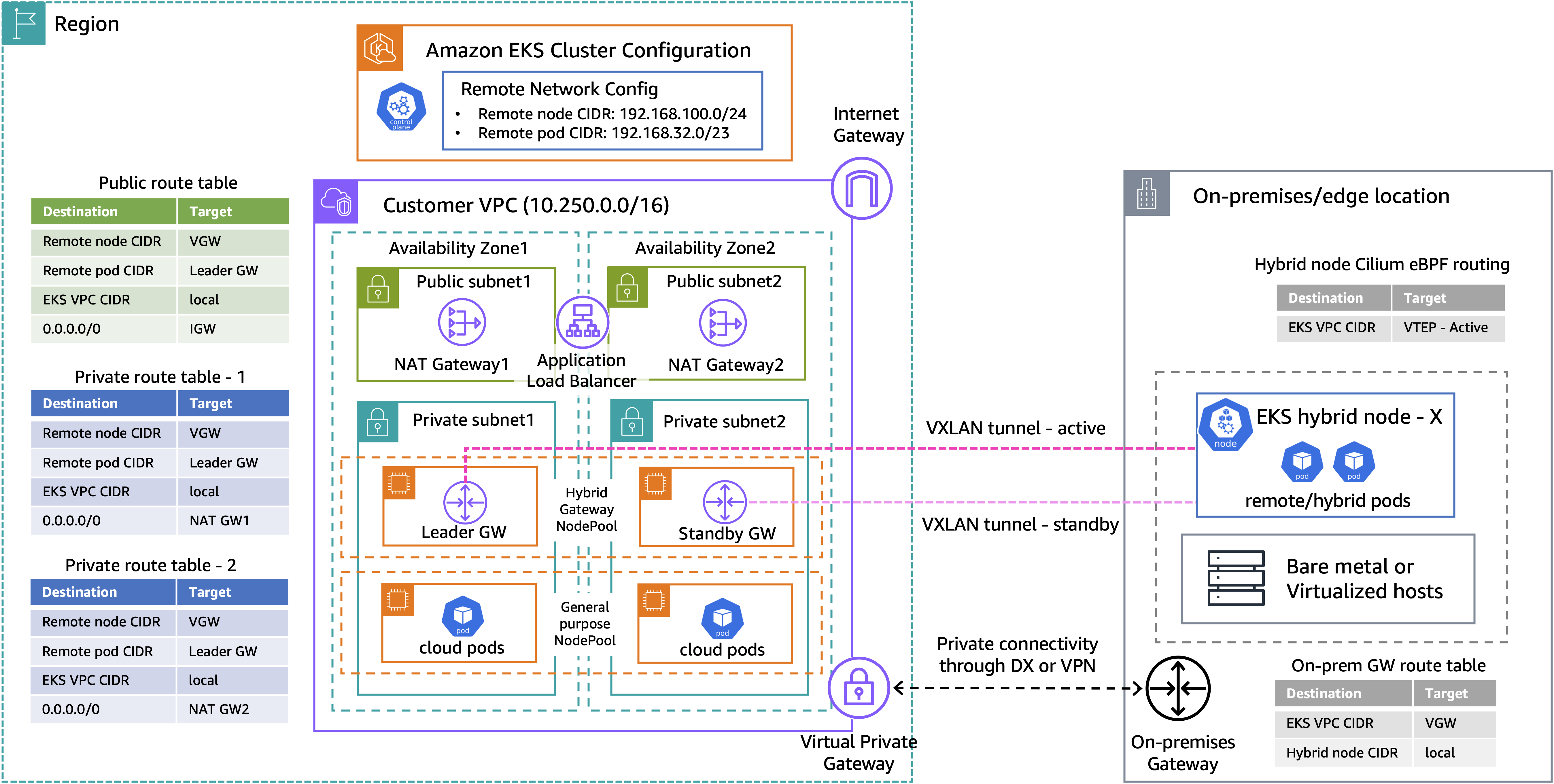
Figure 1: Amazon EKS Hybrid Nodes gateway networking architecture
The above diagram presents a high-level architecture for our demo walkthrough. The Amazon VPC consists of two public subnets and two private subnets for hosting the EKS Auto Mode worker nodes. When using the Amazon EKS Hybrid Nodes gateway, the existing networking prerequisites for EKS Hybrid Nodes still apply, except that the remote pod network no longer needs to be routable. You can use either AWS Direct Connect or AWS Site-to-Site VPN to build private network connectivity between your on-premises environment and the EKS VPC. Additionally, security groups and firewall rules must be configured to allow bidirectional communication between environments, including UDP port 8472 for VXLAN traffic.
Once the gateway pair is deployed, the leader updates the configured VPC route tables with the remote pod CIDR pointing to its own primary ENI. It also creates the CiliumVTEPConfig resource so that Cilium agents on the hybrid nodes forward VPC-bound traffic through the leader’s VXLAN tunnel, ensuring symmetric routing paths.
For illustration purposes, we use the following CIDRs for the demo setup:
- Amazon EKS VPC CIDR: 10.250.0.0/16
- On-premises Node CIDR (
RemoteNodeNetwork): 192.168.100.0/24 - On-premises Pod CIDR (
RemotePodNetwork): 192.168.32.0/23
Prerequisites
The following prerequisites are necessary to complete this solution:
- Amazon VPC with two private and two public subnets, across two AZs.
- On-premises compute nodes running a compatible operating system.
- Private connectivity between the on-premises network and Amazon VPC (through VPN or Direct Connect).
- Two RFC-1918 or CGNAT CIDR blocks for
RemoteNodeNetworkandRemotePodNetwork - Configure the on-premises firewall and the EKS cluster security groups to allow bi-directional communications between environments, as per the networking prerequisites.
- The following tools:
Walkthrough
The following steps walk you through how to deploy Amazon EKS Hybrid Nodes gateway across a hybrid EKS cluster enabled with EKS Auto Mode and EKS Hybrid Nodes.
Creating an EKS cluster enabled with EKS Auto Mode and EKS Hybrid Nodes
- First, we prepare a
cluster-configuration.yamlClusterConfig file, which includes theautoModeConfigthat enables EKS Auto Mode and theremoteNetworkConfigthat enables EKS Hybrid Nodes. Replace theRemoteNodeNetworkandRemotePodNetworkCIDRs based on your own network requirements.
- Deploy the EKS cluster using the ClusterConfig file.
- Wait for the cluster state to become
Active.
Prepare hybrid nodes
- Install the kube-proxy and CoreDNS add-ons required by EKS Hybrid Nodes. To learn more about deploying Amazon EKS add-ons with EKS Hybrid Nodes, see Configure add-ons for hybrid nodes.
- Amazon EKS Hybrid Nodes use temporary AWS Identity and Access Management (IAM) credentials provisioned by AWS Systems Manager hybrid activations or AWS IAM Roles Anywhere to authenticate with the EKS cluster. Follow the Amazon EKS user guide to create the required Hybrid Nodes IAM role (
AmazonEKSHybridNodesRole) using either one of the two options. Then, create an Amazon EKS access entry for Hybrid Nodes IAM role to enable your hybrid nodes to join the cluster. - Use EKS Hybrid Nodes CLI (nodeadm) to bootstrap and install all required components for your hybrid nodes to connect to the cluster. See Connect hybrid nodes in the EKS user guide for details. Prepare a
nodeConfig.yamlconfiguration file using the temporary IAM credentials from the last step. The following is an example for using Systems Manager hybrid activations for hybrid nodes credentials.
- Run the
nodeadm initcommand with yournodeConfig.yamlto join your hybrid nodes to the EKS cluster.
- Install a compatible version of Cilium on EKS Hybrid Nodes using Helm with the preceding configuration.
- Verify the hybrid nodes are in
Readystatus, and theCiliumVTEPConfigCRD is installed correctly.
- Next, prepare a
gateway-nodepool.yamlto define theNodePoolandNodeClassconfigurations. TheadvancedNetworking.sourceDestCheck: DisabledPrimaryENIsetting disables EC2 source/destination check on the node’s primary ENI, allowing the gateway to forward transit traffic. Thehybrid-gateway-node: NoScheduletaint ensures only gateway pods with a matching toleration are scheduled on these nodes, and thehybrid-gateway-node: "true"label is used by the gateway installation Helm chart to target gateway pods deployment to these nodes. See Get started with EKS Hybrid Nodes gateway in the EKS user guide for further details.
- Create the EKS Auto Mode NodePool and NodeClass for gateway installation.
Create IAM policy for VPC route table management
- The gateway nodes need IAM permissions to manage VPC route tables and update route entries for remote pod network. Create an IAM policy
gateway-iam-policy.jsonwith the following permissions.
- Apply the IAM policy to the EKS Auto Mode node role.
Update EKS cluster security group to allow VXLAN traffic
- To allow VXLAN tunnel traffic, add an inbound rule for UDP port 8472 from the remote node network CIDR to the EKS cluster security group. Ensure the corresponding rule is also applied at your on-premises firewall.
Install EKS Hybrid Nodes gateway
- Use an AWS provided helm chart to deploy the EKS Hybrid Nodes gateway. Include all the VPC route tables that are required to communicate with the remote pod networks.
- Validate that both gateway pods are running and note they are automatically spread across two AZs. The gateway pods use their node’s IP addresses because the Helm chart deploys them with
hostNetwork: true.
- Use the following command to identify which gateway pod has been elected as the leader. We can also confirm the leader is on node i-0cded7fb2ff632e2c by matching its node IP (10.250.3.111).
- Next, verify the relevant VPC route tables are updated with the remote pod CIDR pointing to the primary ENI of the leader node instance.
- Confirm the
CiliumVTEPConfigresource has been created by the gateway and synced to the Cilium agents on the hybrid nodes, with the remote VTEP set to the leader gateway (10.250.3.111).
- Lastly, confirm the source/destination check has been disabled on both hybrid gateway nodes.
- Run bidirectional ping tests to verify the pods can communicate with each other across environments.
- Run traceroute tests to validate pod-to-pod traffic is passing through the leader gateway’s VXLAN tunnel.
VPC-to-hybrid pod test
- To test VPC-to-hybrid pod communication, we use an EC2 instance (10.250.0.7) deployed within the same VPC. Confirm that traffic is routed via the VPC route table and forwarded through the leader gateway’s VXLAN tunnel. This direct connectivity between EKS VPC and on-premises hybrid pods also enables additional use cases such as control plane webhook communications and AWS service integrations across hybrid environments.
Failover test
- To test the gateway automatic failover capability, run a continuous ping from the cloud pod to the hybrid pod using the -D flag to print timestamps:
- While the ping is running, use the following command to remove the leader gateway’s node and terminate the underlying EC2 instance. This simulates a sudden node failure, forcing the standby gateway to take over leadership.
- Observe the ping output, in our case packets 5 through 9 are lost during the failover, with traffic resuming at packet 10. The timestamps show the failover completed in approximately 6.2 seconds.
- As expected, we can see the leader gateway is now failed over to 10.250.1.31, which is the previous standby gateway.
Cleaning up
To avoid incurring long-term charges, delete the AWS resources created as part of the demo walkthrough.
Uninstalling the hybrid nodes gateway does not automatically remove the VPC route table entries created by the gateway. Use the following command to clean the routes for your remote pod CIDRs from the VPC route tables.
Clean up other prerequisite resources that you created if they’re no longer needed.
Additional considerations
The Amazon EKS Hybrid Nodes gateway is available in all AWS Regions where EKS Hybrid Nodes is supported, except China Regions. There is no additional charge for using the gateway itself. You pay for the EC2 instances hosting the gateway pods and any applicable EKS Auto Mode management fees. For more information, see the Amazon EKS pricing.
Gateway scalability is determined by the EC2 instance performance – including network bandwidth, packets per second (PPS), and the number of concurrent VXLAN tunnels (hybrid nodes). As a general guidance, an instance type such as c6i.xlarge or m6i.xlarge is suitable for most deployments. Refer to the Amazon EKS Hybrid Nodes gateway operations in the EKS user guide for additional information.
Each gateway deployment serves a single EKS cluster, and you must deploy a separate gateway pair for each cluster. Note that the gateway does not provide built-in traffic encryption. If you require encryption in transit across hybrid cloud environments, consider using AWS Direct Connect with MACsec or a VPN connection.
Conclusion
In this post, we walked through deploying the Amazon EKS Hybrid Nodes gateway to simplify hybrid Kubernetes networking between your EKS cluster VPC and on-premises hybrid nodes. The gateway automates VXLAN tunnel management and VPC route table updates, enabling seamless pod-to-pod communication, webhook connectivity, and AWS service integration across hybrid environments, without requiring changes to your existing on-premises network infrastructure.
To learn more about Amazon EKS Hybrid Nodes and EKS Hybrid Nodes gateway, see the following resources:
- Amazon EKS User Guide: Get started with EKS Hybrid Nodes gateway
- AWS Blog: A deep dive into Amazon EKS Hybrid Nodes
- AWS Blog: Deep dive into cluster networking for Amazon EKS Hybrid Nodes
- AWS re:Invent 2024 session (KUB205) – Bring the power of Amazon EKS to your on-premises applications