Networking & Content Delivery
Centralized VPC inspection with Amazon VPC Route Server and AWS Transit Gateway
Centralized VPC inspection with Amazon VPC Route Server and AWS Transit Gateway helps you route traffic from multiple virtual private clouds (VPCs) through a shared firewall for security enforcement. Spoke VPCs send traffic through AWS Transit Gateway to a dedicated inspection VPC, where firewall appliances examine it before forwarding. The challenge is making this inspection path resilient. Consider what happens when your active firewall fails.
In the post Dynamic routing using Amazon VPC Route Server, you learn how Amazon VPC Route Server uses dynamic BGP-based routing within Amazon Virtual Private Cloud (Amazon VPC) for floating IP failover and VPC ingress inspection. This post extends those patterns to centralized multi-VPC inspection architectures using AWS Transit Gateway, covering three scenarios:
- East-west inspection — Spoke VPC to spoke VPC traffic routed through centralized inspection with active-standby failover
- North-south inspection — Spoke VPC to internet traffic inspected before exiting to the internet
- Availability Zone (AZ)-affinity inspection — Traffic stays within its local Availability Zone under normal conditions, with cross-AZ failover only during failures
Each scenario builds on the previous one. To follow along, you need familiarity with BGP concepts such as Autonomous System Number (ASN), AS-path, and peering. You also need experience working with AWS Transit Gateway and VPC networking. This walkthrough uses GoBGP as a lightweight BGP speaker on the inspection instances. For production deployments, replace GoBGP with your preferred network virtual appliance (for example, a vendor firewall appliance that supports BGP).
When to use this pattern
We recommend Gateway Load Balancer as the first choice for high availability with inspection appliances. However, it might not fit your use case when:
- Your appliance does not support the GENEVE protocol
- You need active-standby rather than active-active failover
- You need fine-grained routing control using BGP attributes such as AS-path or Multi-Exit Discriminator (MED)
If any of these apply, the Amazon VPC Route Server approach described in this post provides an alternative.
Prerequisites
Before you begin, make sure you have:
- An AWS account and permissions to create and manage the following AWS resources. Refer to this GitHub aws-samples repo for the specific AWS Identity and Access Management (IAM) permissions required for each service:
- Amazon VPC — VPCs, subnets, route tables, security groups, internet gateways
- AWS Transit Gateway — transit gateways, route tables, VPC attachments
- VPC Route Server— route server, endpoints, peers, propagation
- Amazon EC2 — instances, EC2 Instance Connect endpoints
- AWS CloudFormation — stack creation and management
- AWS CLI configured, or access to the AWS Management Console
- Amazon VPC Route Server available in your target AWS Region
**Important:** This architecture is provided for demonstration purposes. Do not deploy in production environments without conducting a full security review, implementing encryption in transit, configuring appropriate security groups and NACLs and adding monitoring and logging.
Scenario 1: East-west inspection (spoke-to-spoke)
In this scenario, two spoke VPCs communicate through a Transit Gateway. All traffic passes through a centralized inspection VPC where firewall appliances examine it before forwarding. Figure 1 shows an example. The VPC Route Server dynamically steers traffic to the active firewall using BGP, with automatic failover to a standby.
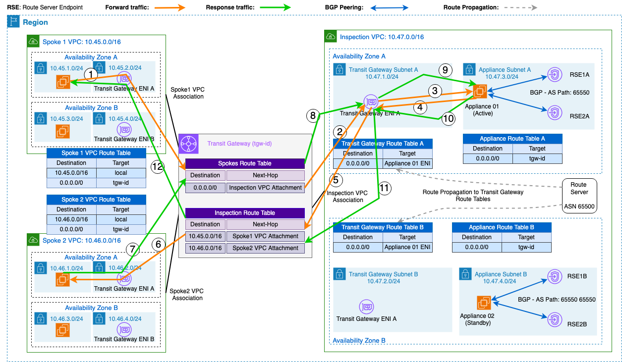
Figure 1: East-west traffic flow through centralized inspection with active-standby failover
Architecture
The deployment consists of:
- AWS Transit Gateway with two route tables: a spokes route table (default route to the inspection VPC attachment) and an inspection route table (propagated spoke routes).
- Spoke1 VPC (10.45.0.0/16) and Spoke2 VPC (10.46.0.0/16), each with an Amazon Elastic Compute Cloud (Amazon EC2) instance and Transit Gateway attachment.
- Inspection VPC (10.47.0.0/16) with two firewall instances (one per Availability Zone), a VPC Route Server (ASN 65500) with two endpoints per Availability Zone, and route server propagation enabled on the Transit Gateway subnet route tables.
How active-standby failover works with BGP AS-path prepending
Both firewall instances advertise 10.0.0.0/8 to the route server through BGP, but they use different AS-path lengths:
| Instance | AS Path | Effect |
| fw01 in AZ1 (active) | 65550 | Shorter path — preferred by route server |
| fw02 in AZ2 (standby) | 65550 65550 | Prepended path — selected only when fw01 is unavailable |
The route server propagates the preferred route into the Transit Gateway subnet route tables in both Availability Zones, directing traffic to fw01. If fw01’s BGP session drops, the route server updates the route tables to point to fw02.
Life of a packet: Spoke1 to Spoke2
Forward path:
- Spoke1 instance sends a packet to a resource in Spoke2 VPC. The instance subnet default route (0.0.0.0/0) forwards it to the Transit Gateway.
- The spokes route table has a default route pointing to the inspection VPC attachment. Transit Gateway forwards the packet to the inspection VPC.
- The packet enters the TGW subnet in the inspection VPC. The route server has propagated `10.0.0.0/8 → fw01 ENI` into this subnet’s route table, so the packet is delivered to fw01.
- fw01 inspects the packet, then forwards it back to the Transit Gateway (the public subnet route table has `10.0.0.0/8 → TGW`).
- The inspection route table has Spoke2’s CIDR (10.46.0.0/16) propagated from the Spoke2 attachment. Transit Gateway delivers the packet to the Spoke2 instance.
Return path:
The same sequence in reverse: Spoke2 → TGW (spokes route table) → inspection VPC TGW subnet → fw01 inspects → TGW (inspection route table) → Spoke1.
Deploy and verify
To deploy the architecture:
- Navigate to the AWS CloudFormation console in your desired AWS Region.
- Create a new stack using the AWS CloudFormation template in this GitHub aws-samples repo. Please note that this template will deploy GoBGP as a lightweight BGP speaker on the inspection instances.
To verify BGP peering, connect to the fw01 instance using EC2 Instance Connect Endpoint and run:
/usr/local/bin/gobgp neighbor
Peer AS Up/Down State | #Received Accepted<rs-endpoint-ip> 65500 00:05:00 Establ | 0 0
The output shows the route server endpoints as established BGP neighbors.
To verify the advertised route:
/usr/local/bin/gobgp global rib
Network Next Hop AS_PATH Age*> 10.0.0.0/8 <instance-ip> 65550 00:05:00
The expected output shows 10.0.0.0/8 with AS-path 65550. Repeat for fw02 — the output shows AS-path 65550 65550.
Check the AWS Transit Gateway subnet route table in the inspection VPC. The route server propagates 10.0.0.0/8 pointing to fw01’s elastic network interface (ENI).
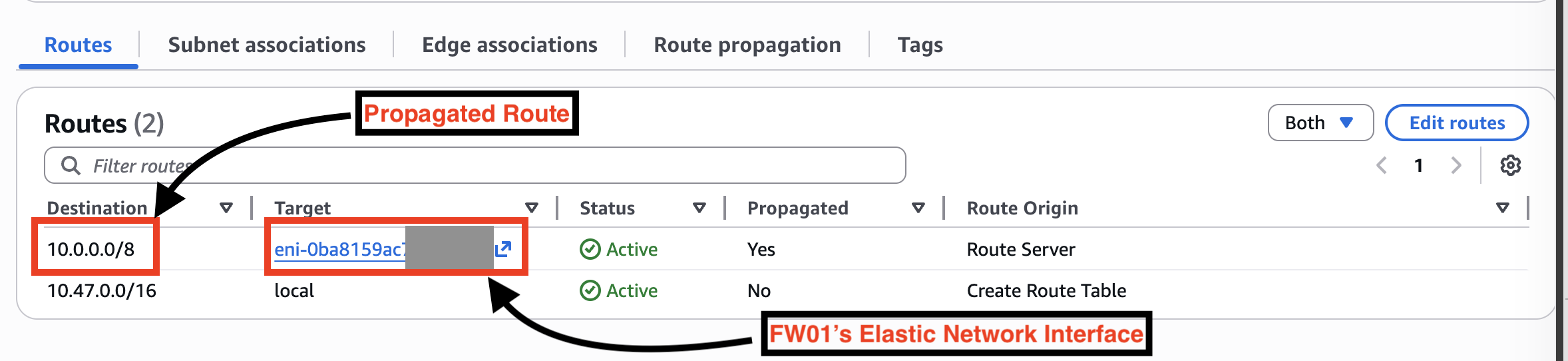
Figure 2: Propagated route in the AWS Transit Gateway subnet route table
Test connectivity
Connect to the Spoke1 instance and run a ping and traceroute to the Spoke2 instance:
ec2-user@ip-10-45-1-205 ~ $ ping 10.46.1.48PING 10.46.1.48 (10.46.1.48) 56(84) bytes of data.64 bytes from 10.46.1.48: icmp_seq=1 ttl=124 time=2.09 ms64 bytes from 10.46.1.48: icmp_seq=2 ttl=124 time=1.75 ms64 bytes from 10.46.1.48: icmp_seq=3 ttl=124 time=1.03 ms
ec2-user@ip-10-45-1-205 ~ $ traceroute 10.46.1.48 1 * * * 2 ip-10-47-3-42.us-west-2.compute.internal (10.47.3.42) 1.084 ms 3 * * * 4 ip-10-46-1-48.us-west-2.compute.internal (10.46.1.48) 1.939 ms
Hop 2 confirms that traffic passes through the fw01 inspection instance (10.47.3.42) in AZ1.
Test failover
Stop the fw01 instance to simulate a failure:
aws ec2 stop-instances --instance-ids <fw01-instance-id>
The route server detects the BGP session drop and updates the route tables to point to fw02. Enabling Bidirectional Forwarding Detection (BFD) reduces detection time to sub-second convergence, as discussed in the original Amazon VPC Route Server blog post. The route now points to the AZ2 instance’s network interface.
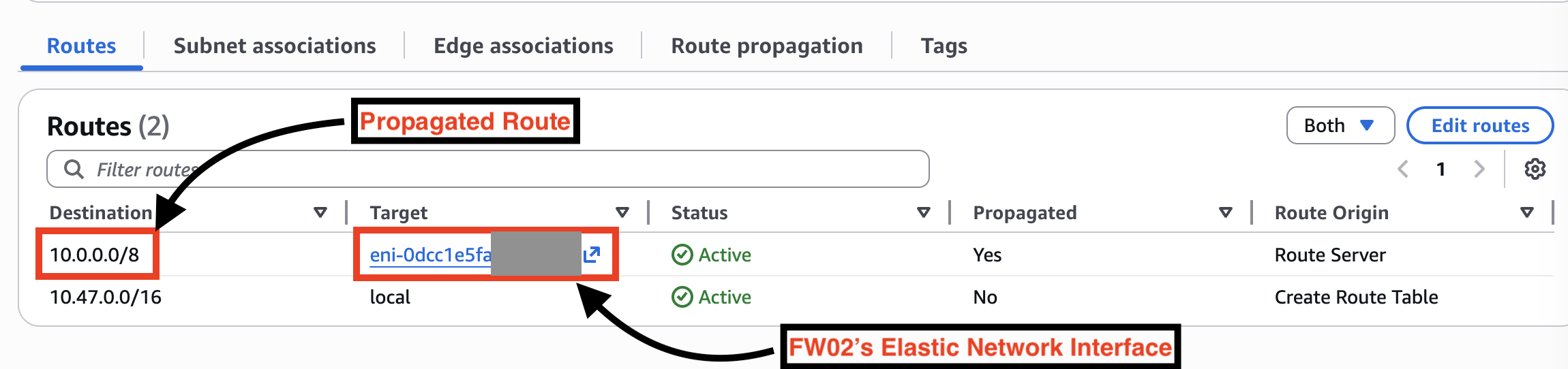
Figure 3: Propagated route in the Transit Gateway subnet route table after failover
Run the ping and traceroute again. Hop 2 now shows fw02’s IP in AZ2, confirming failover. Start fw01 to restore the preferred path automatically.
ec2-user@ip-10-45-1-205 ~ $ ping 10.46.1.48PING 10.46.1.48 (10.46.1.48) 56(84) bytes of data.64 bytes from 10.46.1.48: icmp_seq=1 ttl=124 time=2.57 ms64 bytes from 10.46.1.48: icmp_seq=2 ttl=124 time=1.84 ms64 bytes from 10.46.1.48: icmp_seq=3 ttl=124 time=1.68 ms
ec2-user@ip-10-45-1-205 ~ $ traceroute 10.46.1.48traceroute to 10.46.1.48 (10.46.1.48), 30 hops max, 60 byte packets 1 * * * 2 ip-10-47-4-229.us-west-2.compute.internal (10.47.4.229) 1.523 ms 1.511 ms 1.603 ms 3 * * * 4 ip-10-46-1-48.us-west-2.compute.internal (10.46.1.48) 2.418 ms 2.452 ms 2.594 ms
Scenario 2: North-south inspection (spoke-to-internet)
This scenario extends the east-west architecture to handle internet-bound traffic. Spoke instances send traffic to the internet through the same inspection path. After the firewall inspects the traffic, it exits through the inspection VPC’s internet gateway. This is demonstrated in the following diagram (figure 4).
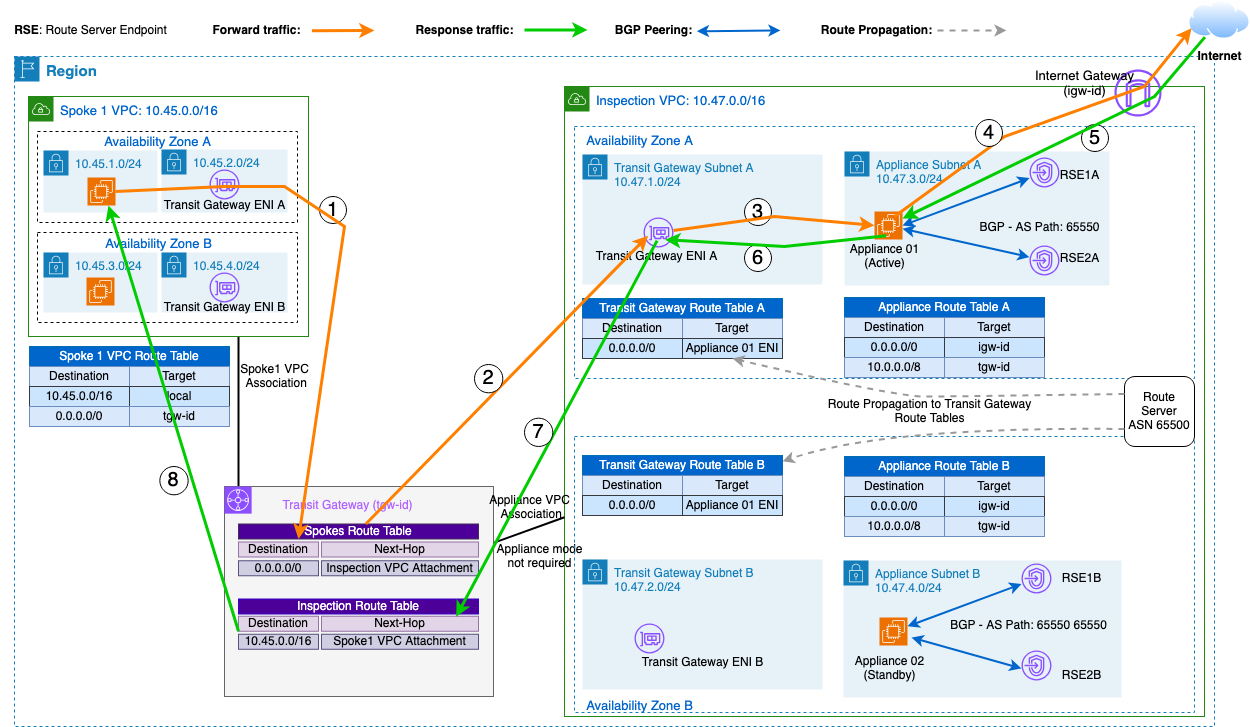
Figure 4: North-south traffic flow through centralized inspection to the internet
What changes for north-south inspection
The inspection VPC adds an internet gateway and public subnets. The firewall instances have two sets of routes:
| Destination | Next hop | Purpose |
| 0.0.0.0/0 | Internet gateway | Internet-bound traffic after inspection |
| 10.0.0.0/8 | Transit Gateway | Return traffic to spoke VPCs |
The firewall advertises 10.0.0.0/8 to the route server (same as Scenario 1). Optionally, it also advertises 0.0.0.0/0 to attract all traffic, including internet-bound flows.
Life of a packet: Spoke to internet and back
Forward path:
- Spoke1 instance sends a packet to a resource on the internet. The default route forwards it to the Transit Gateway.
- The spokes route table forwards the packet to the inspection VPC attachment.
- The TGW subnet route table directs the packet to fw01 (via the route server-propagated route, or a `0.0.0.0/0` advertisement from the firewall).
- fw01 inspects the packet and forwards it toward the internet gateway. The public subnet route table has `0.0.0.0/0 → IGW`. The internet gateway sends the packet to the internet.
Return path:
- Return traffic arrives at the internet gateway and is delivered to fw01.
6-7. fw01 inspects the return packet. The destination (10.45.x.x) matches the `10.0.0.0/8 → TGW` route, so the packet goes to Transit Gateway.
- The inspection route table matches Spoke1’s CIDR and delivers the packet to the Spoke1 instance.
The active-standby mechanism and failover behaviors are identical to Scenario 1.
Scenario 3: Avoiding cross-AZ traffic under normal conditions
In Scenarios 1 and 2, a single route server selects one winning route and propagates it to all associated subnet route tables. As a result, traffic from both Availability Zones goes to the same firewall, even when that firewall is in a different Availability Zone. For workloads where cross-AZ data transfer adds latency or cost, you deploy two route servers to achieve AZ-affinity. This is shown in the following diagram (figure 5).
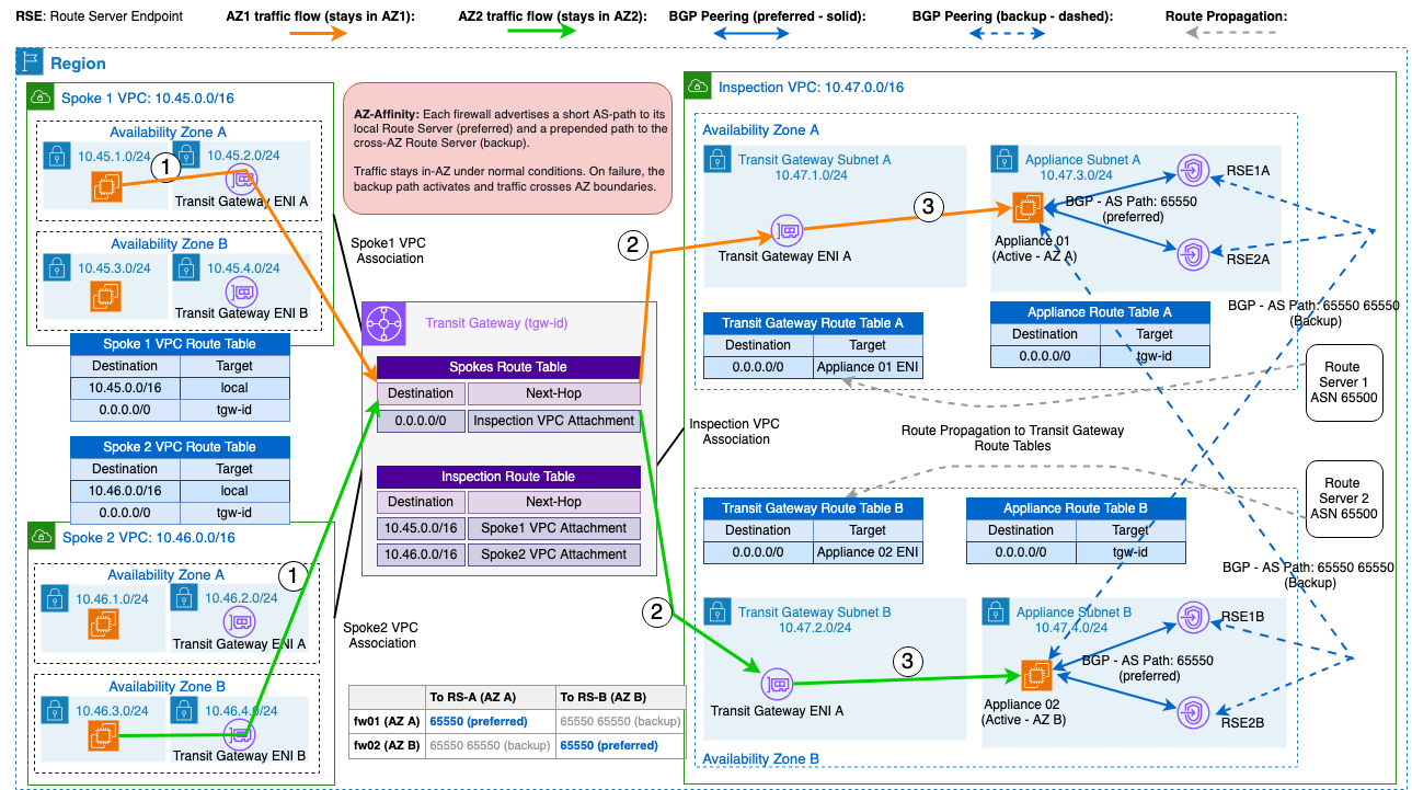
Figure 5: AZ-affinity inspection with two route servers keeping traffic local under normal conditions
How AZ-affinity routing works with dual route servers
You deploy two route servers, one per Availability Zone. Each firewall peers with both route servers but advertises different AS-path lengths depending on whether the route server is local or remote:
| Firewall | To Route Server A (AZ1) | To Route Server B (AZ2) |
| fw01 (AZ1) | AS-path: 65550 (preferred) | AS-path: 65550 65550 (backup) |
| fw02 (AZ2) | AS-path: 65550 65550 (backup) | AS-path: 65550 (preferred) |
Route Server A propagates routes only to the AZ1 Transit Gateway subnet route table, and Route Server B only to the AZ2 Transit Gateway subnet route table. Under normal conditions:
- Traffic entering through the AZ1 Transit Gateway ENI goes to fw01 (local)
- Traffic entering through the AZ2 Transit Gateway ENI goes to fw02 (local)
No traffic crosses the Availability Zone boundary.
Life of a packet: AZ-affinity routing
Normal operation:
The packet flow is identical to Scenario 1, except each AZ’s TGW subnet route table points to its local firewall. Traffic entering through AZ1 is inspected by fw01; traffic entering through AZ2 is inspected by fw02. No cross-AZ hop occurs.
Failover:
If fw01 fails, Route Server A loses the preferred path and selects fw02’s backup advertisement. The AZ1 TGW subnet route table updates to point to fw02 in AZ2. Only AZ1 traffic crosses the boundary — AZ2 traffic is unaffected. When fw01 recovers, Route Server A reverts to the shorter AS-path automatically.
Comparing the approaches
| Aspect | Single route server (Scenarios 1-2) | Two route servers (Scenario 3) |
| Route servers | One, shared across Availability Zones | One per Availability Zone |
| Normal traffic path | All traffic to one active firewall | Each Availability Zone routes to its local firewall |
| Cross-AZ traffic | Always (standby is in the other Availability Zone) | Only during failover |
| Failover scope | Global — all traffic shifts | Per-AZ — only the affected Availability Zone shifts |
| BGP configuration | Same AS-path to all endpoints | Differentiated AS-paths per route server |
Cleanup
To avoid unnecessary costs from resources deployed via the GitHub CloudFormation template, delete all resources by deleting the CloudFormation stack. Follow the documentation for the steps.
Considerations
- Use BFD or other rapid-failure-detection tools for faster convergence.
- The firewall instances require static routes on their subnet route table to forward inspected traffic (`10.0.0.0/8 → Transit Gateway` for return traffic, `0.0.0.0/0 → Internet Gateway` for internet egress). The route server does not manage these.
- Follow security best practices for security groups:
-
- Firewall ENIs (data plane): Allow only required traffic from spoke VPC CIDRs.
- Firewall ENIs (control plane): Restrict BGP traffic (TCP 179) to VPC Route Server endpoint IPs or their subnet CIDRs only.
- Spoke instances: Apply least-privilege ingress/egress rules.
- When building the example we showed, you must consider the pricing of each specific service:
Conclusion
In this post, you used Amazon VPC Route Server in a centralized multi-VPC inspection architecture using Transit Gateway to leverage BGP for automatic firewall failover, giving you a resilient inspection path even when your appliance can’t support the usual failover options. Scenario 1 demonstrated east-west inspection with active-standby failover for spoke-to-spoke traffic. Scenario 2 extended the same pattern to north-south traffic flowing to the internet. Scenario 3 introduced AZ-affinity using two route servers with differentiated AS-path advertisements to keep traffic local under normal conditions.
The same VPC Route Server implementation applies if you use AWS Cloud WAN instead of AWS Transit Gateway for connectivity.
To learn more, see the Amazon VPC Route Server documentation.
About the author

Murimi George
Murimi is a Senior Cloud Support Engineer in Cape Town, specializing in AWS networking. He draws on over 10 years of cross-industry experience to help customers troubleshoot complex issues and design resilient, secure network architectures. When he’s not solving networking puzzles, you’ll find him on the football pitch, tennis court, or tearing up trails on his motorcycle.