AWS Architecture Blog
Disaster Recovery (DR) for a Third-party Interactive Voice Response on AWS
Voice calling systems are prevalent and necessary to many businesses today. They are usually designed to provide a 24×7 helpline support across multiple domains and use cases. Reliability and availability of such systems are important for a good customer experience. The thoughtful design of a cost-optimized solution will allow your business to sustain the system into the future.
We address a scenario in which you are mandated to host the workload on a corporate data center (DC), and configure the backup site on Amazon Web Services (AWS). Since the primary objective of a backup site is disaster recovery (DR) management, this site is often referred to as a DR site.
Disaster Recovery on AWS
DR strategy defines the recovery objectives for downtime and data loss. The workload has a recovery time objective (RTO) and a recovery point objective (RPO). RTO is the maximum acceptable delay between the interruption of service and the restoration of service. RPO is the maximum acceptable amount of time since the last data recovery point. AWS defines four DR strategies in increasing order of complexity, and decreasing order of RTO and RPO. These are backup and restore, active/passive (pilot light or warm standby), or active/active.
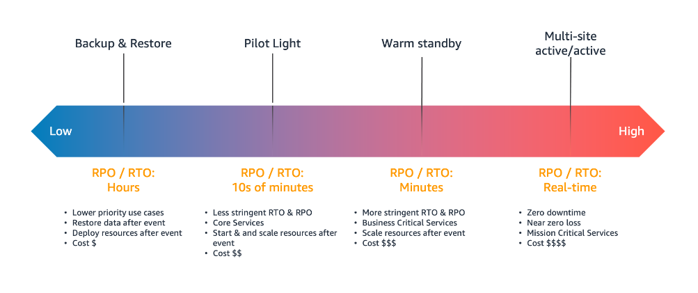
Figure 1. Disaster recovery (DR) options
In our use case, the DR site on AWS must serve the user traffic with RPO and RTO in seconds. Warm standby is the optimal choice in this case. It is a scaled-down version of a fully functional environment, and is always running in the cloud.
This architecture enables customers facing challenges of cost overhead with redundant Session Initiation Protocol (SIP) trunks for the DC and DR sites. It allows you to optimize your spend and yet retain a reliable workflow.
SIP trunk communication on AWS
Let’s see how the SIP trunk termination on the AWS network handles the failover scenario of a third-party IVR application installed on Amazon EC2 at the DR site.
There will be two connections made from the AWS Direct Connect location (DX). The first will be for a point-to-point connectivity between the corporate DC and the AWS DR site. The second connection will be originating from the multiplexer (MUX) of the telecom provider who is providing you the SIP trunk.
The telecom provider will lay the SIP trunk from its MUX to the customer router at the DX location. At this point, the mode of communication becomes IP-based. The telecom provider will send the call to the IP address attached to the Network Load Balancer (NLB) in Amazon Virtual Private Cloud (VPC).

Figure 2. Communication circuitry at telecom side
AWS Network Load Balancers can now distribute traffic to AWS resources using their IP addresses and instance IDs as targets. You can also distribute the traffic with on-premises resources over AWS Direct Connect. Load balancing across AWS and on-premises resources using the same load balancer streamlines migrate-to-cloud, burst-to-cloud, or failover-to-cloud.
In the backup site, the NLB will point to the Session Border Controller (SBC). This is a special-purpose device that protects and regulates IP communications flows. You can bring your own SBC, or you can use an SBC offered in the AWS Marketplace.
Best practices for high availability of IVR solution on AWS
- Configure the multiple Availability Zone (Multi-AZ) SBC setup
- Make sure that the telecom provider for the SIP trunk is different from the internet service provider (ISP). This is for last mile connectivity for the DC from Direct Connect
- Consider redundancy for Direct Connect by using a Site-to-Site VPN tunnel

Figure 3. Solution architecture of DR on AWS for a third-party IVR solution
Communication flow for an IVR solution deployed on a corporate DC and its DR on AWS
- The callers are received on the telecom providers SIP line, which terminates on the AWS Direct Connect location.
- At the DX location, you will configure a route in the AWS router to send the traffic to the IP address of the NLB. The NLB should be configured to perform health checks on the virtual machine in your on-premises DC. Based on these health checks, the NLB will do the routing and the failover.
- In a live scenario with successful health checks at the DC, the NLB will forward the call to the IP of the on-premises virtual machine. This is where the IVR application will be installed.
- The communication between the NLB in Amazon VPC and the virtual machine in DC, will happen over Direct Connect.
- In a DR scenario, the NLB will failover the communication to SBCs in Amazon VPC.
Conclusion
This solution is useful when a third-party IVR system is deployed in a corporate data center, and the passive DR site is hosted on AWS. Cost optimization on telecom components is an important aspect of this design. AWS Direct Connect provides dedicated connectivity to the AWS environment, from 50 Mbps up to 10 Gbps. This gives you managed and controlled latency. It also provides provisioned bandwidth, so your workload can connect to AWS resources in a reliable, scalable, and cost-effective way.
The solution in this blog explains the end-to-end flow of communication, from the user to the IVR agents. It also provides insights into managing failover and failback between DR and the DR site.
Further Reading: