AWS Compute Blog
Building an AWS IoT Core device using AWS Serverless and an ESP32
Using a simple Arduino sketch, an AWS Serverless Application Repository application, and a microcontroller, you can build a basic serverless workflow for communicating with an AWS IoT Core device.
A microcontroller is a programmable chip and acts as the brain of an electronic device. It has input and output pins for reading and writing on digital or analog components. Those components could be sensors, relays, actuators, or various other devices. It can be used to build remote sensors, home automation products, robots, and much more. The ESP32 is a powerful low-cost microcontroller with Wi-Fi and Bluetooth built in and is used this walkthrough.
The Arduino IDE, a lightweight development environment for hardware, can be used to program an ESP32. There is a large collection of community and officially supported libraries, from addressable LED strips to spectral light analysis.

The following demonstrates connecting an ESP32 to AWS IoT Core to allow it to publish and subscribe to topics. This means that the device can send any arbitrary information, such as sensor values, into AWS IoT Core while also being able to receive commands.
Solution overview
This post walks through deploying an application from the AWS Serverless Application Repository. This allows an AWS IoT device to be messaged using a REST endpoint powered by Amazon API Gateway and AWS Lambda. The AWS SAR application also configures an AWS IoT rule that forwards any messages published by the device to a Lambda function that updates an Amazon DynamoDB table, demonstrating basic bidirectional communication.
The last section explores how to build an IoT project with real-world application. By connecting a thermal printer module and modifying a few lines of code in the example firmware, the ESP32 device becomes an AWS IoT–connected printer.
All of this can be accomplished within the AWS Free Tier, which is necessary for the following instructions.

An example of an AWS IoT project using an ESP32, AWS IoT Core, and an Arduino thermal printer.
Required steps
To complete the walkthrough, follow these steps:
- Create an AWS IoT device.
- Install and configure the Arduino IDE.
- Configure and flash an ESP32 IoT device.
- Deploying the lambda-iot-rule AWS SAR application.
- Monitor and test.
- Create an IoT thermal printer.
Creating an AWS IoT device
To communicate with the ESP32 device, it must connect to AWS IoT Core with device credentials. You must also specify the topics it has permissions to publish and subscribe on.
- In the AWS IoT console, choose Register a new thing, Create a single thing.
- Name the new thing MyNewESP32. Leave the remaining fields set to their defaults. Choose Next.
- Choose Create certificate. Only the thing cert, private key, and Amazon Root CA 1 downloads are necessary for the ESP32 to connect. Download and save them somewhere secure, as they are used when programming the ESP32 device.
- Choose Activate, Attach a policy.
- Skip adding a policy, and choose Register Thing.
- In the AWS IoT console side menu, choose Secure, Policies, Create a policy.
- Name the policy Esp32Policy. Choose the Advanced tab.
- Paste in the following policy template.
{ "Version": "2012-10-17", "Statement": [ { "Effect": "Allow", "Action": "iot:Connect", "Resource": "arn:aws:iot:REGION:ACCOUNT_ID:client/MyNewESP32" }, { "Effect": "Allow", "Action": "iot:Subscribe", "Resource": "arn:aws:iot:REGION:ACCOUNT_ID:topicfilter/esp32/sub" }, { "Effect": "Allow", "Action": "iot:Receive", "Resource": "arn:aws:iot:REGION:ACCOUNT_ID:topic/esp32/sub" }, { "Effect": "Allow", "Action": "iot:Publish", "Resource": "arn:aws:iot:REGION:ACCOUNT_ID:topic/esp32/pub" } ] } - Replace REGION with the matching AWS Region you’re currently operating in. This can be found on the top right corner of the AWS console window.
- Replace ACCOUNT_ID with your own, which can be found in Account Settings.
- Choose Create.
- In the AWS IoT console, choose Secure, Certification. Select the one created for your device and choose Actions, Attach policy.
- Choose Esp32Policy, Attach.
Your AWS IoT device is now configured to have permission to connect to AWS IoT Core. It can also publish to the topic esp32/pub and subscribe to the topic esp32/sub. For more information on securing devices, see AWS IoT Policies.
Installing and configuring the Arduino IDE
The Arduino IDE is an open-source development environment for programming microcontrollers. It can support a continuously growing number of platforms including most ESP32-based modules. It must be installed along with the ESP32 board definitions, MQTT library, and ArduinoJson library.
- Download the Arduino installer for the desired operating system.
- Start Arduino and open the Preferences window.
- For Additional Board Manager URLs, add
https://dl.espressif.com/dl/package_esp32_index.json. - Choose Tools, Board, Boards Manager.
- Search
esp32and install the latest version. - Choose Sketch, Include Library, Manage Libraries.
- Search
MQTT, and install the latest version by Joel Gaehwiler. - Repeat the library installation process for
ArduinoJson.
The Arduino IDE is now installed and configured with all the board definitions and libraries needed for this walkthrough.
Configuring and flashing an ESP32 IoT device

A collection of various ESP32 development boards.
For this section, you need an ESP32 device. To check if your board is compatible with the Arduino IDE, see the boards.txt file. The following code connects to AWS IoT Core securely using MQTT, a publish and subscribe messaging protocol.
This project has been tested on the following devices:
- Sparkfun ESP32 Thing
- DFRobot Firebeetle ESP32
- TTGO ESP32
- M5Stack Core / M5Stick
- HiLetgo ESP-WROOM-32
- Install the required serial drivers for your device. Some boards use different USB/FTDI chips for interfacing. Here are the most commonly used with links to drivers.
- Open the Arduino IDE and choose File, New to create a new sketch.
- Add a new tab and name it
secrets.h. - Paste the following into the secrets file.
#include <pgmspace.h> #define SECRET #define THINGNAME "" const char WIFI_SSID[] = ""; const char WIFI_PASSWORD[] = ""; const char AWS_IOT_ENDPOINT[] = "xxxxx.amazonaws.com"; // Amazon Root CA 1 static const char AWS_CERT_CA[] PROGMEM = R"EOF( -----BEGIN CERTIFICATE----- -----END CERTIFICATE----- )EOF"; // Device Certificate static const char AWS_CERT_CRT[] PROGMEM = R"KEY( -----BEGIN CERTIFICATE----- -----END CERTIFICATE----- )KEY"; // Device Private Key static const char AWS_CERT_PRIVATE[] PROGMEM = R"KEY( -----BEGIN RSA PRIVATE KEY----- -----END RSA PRIVATE KEY----- )KEY"; - Enter the name of your AWS IoT thing, MyNewESP32, in the field THINGNAME.
- To connect to Wi-Fi, add the SSID and PASSWORD of the desired network. Note: The network name should not include spaces or special characters.
- The AWS_IOT_ENDPOINT can be found from the Settings page in the AWS IoT console.
- Copy the Amazon Root CA 1, Device Certificate, and Device Private Key to their respective locations in the
secrets.hfile. - Choose the tab for the main sketch file, and paste the following.
#include "secrets.h" #include <WiFiClientSecure.h> #include <MQTTClient.h> #include <ArduinoJson.h> #include "WiFi.h" // The MQTT topics that this device should publish/subscribe #define AWS_IOT_PUBLISH_TOPIC "esp32/pub" #define AWS_IOT_SUBSCRIBE_TOPIC "esp32/sub" WiFiClientSecure net = WiFiClientSecure(); MQTTClient client = MQTTClient(256); void connectAWS() { WiFi.mode(WIFI_STA); WiFi.begin(WIFI_SSID, WIFI_PASSWORD); Serial.println("Connecting to Wi-Fi"); while (WiFi.status() != WL_CONNECTED){ delay(500); Serial.print("."); } // Configure WiFiClientSecure to use the AWS IoT device credentials net.setCACert(AWS_CERT_CA); net.setCertificate(AWS_CERT_CRT); net.setPrivateKey(AWS_CERT_PRIVATE); // Connect to the MQTT broker on the AWS endpoint we defined earlier client.begin(AWS_IOT_ENDPOINT, 8883, net); // Create a message handler client.onMessage(messageHandler); Serial.print("Connecting to AWS IOT"); while (!client.connect(THINGNAME)) { Serial.print("."); delay(100); } if(!client.connected()){ Serial.println("AWS IoT Timeout!"); return; } // Subscribe to a topic client.subscribe(AWS_IOT_SUBSCRIBE_TOPIC); Serial.println("AWS IoT Connected!"); } void publishMessage() { StaticJsonDocument<200> doc; doc["time"] = millis(); doc["sensor_a0"] = analogRead(0); char jsonBuffer[512]; serializeJson(doc, jsonBuffer); // print to client client.publish(AWS_IOT_PUBLISH_TOPIC, jsonBuffer); } void messageHandler(String &topic, String &payload) { Serial.println("incoming: " + topic + " - " + payload); // StaticJsonDocument<200> doc; // deserializeJson(doc, payload); // const char* message = doc["message"]; } void setup() { Serial.begin(9600); connectAWS(); } void loop() { publishMessage(); client.loop(); delay(1000); } - Choose File, Save, and give your project a name.
Flashing the ESP32
- Plug the ESP32 board into a USB port on the computer running the Arduino IDE.
- Choose Tools, Board, and then select the matching type of ESP32 module. In this case, a Sparkfun ESP32 Thing was used.
- Choose Tools, Port, and then select the matching port for your device.
- Choose Upload. Arduino reads Done uploading when the upload is successful.
- Choose the magnifying lens icon to open the Serial Monitor. Set the baud rate to 9600.
Keep the Serial Monitor open. When connected to Wi-Fi and then AWS IoT Core, any messages received on the topic esp32/sub are logged to this console. The device is also now publishing to the topic esp32/pub.
The topics are set at the top of the sketch. When changing or adding topics, remember to add permissions in the device policy.
// The MQTT topics that this device should publish/subscribe
#define AWS_IOT_PUBLISH_TOPIC   "esp32/pub"
#define AWS_IOT_SUBSCRIBE_TOPIC "esp32/sub"
Within this sketch, the relevant functions are publishMessage() and messageHandler().
The publishMessage() function creates a JSON object with the current time in milliseconds and the analog value of pin A0 on the device. It then publishes this JSON object to the topic esp32/pub.
void publishMessage()
{
  StaticJsonDocument<200> doc;
  doc["time"] = millis();
  doc["sensor_a0"] = analogRead(0);
  char jsonBuffer[512];
  serializeJson(doc, jsonBuffer); // print to client

  client.publish(AWS_IOT_PUBLISH_TOPIC, jsonBuffer);
}
The messageHandler() function prints out the topic and payload of any message from a subscribed topic. To see all the ways to parse JSON messages in Arduino, see the deserializeJson() example.
void messageHandler(String &topic, String &payload) {
  Serial.println("incoming: " + topic + " - " + payload);

//  StaticJsonDocument<200> doc;
//  deserializeJson(doc, payload);
//  const char* message = doc["message"];
}
Additional topic subscriptions can be added within the connectAWS() function by adding another line similar to the following.
// Subscribe to a topic
  client.subscribe(AWS_IOT_SUBSCRIBE_TOPIC);

  Serial.println("AWS IoT Connected!");
Deploying the lambda-iot-rule AWS SAR application
Now that an ESP32 device has been connected to AWS IoT, the following steps walk through deploying an AWS Serverless Application Repository application. This is a base for building serverless integration with a physical device.
- On the lambda-iot-rule AWS Serverless Application Repository application page, make sure that the Region is the same as the AWS IoT device.
- Choose Deploy.
- Under Application settings, for PublishTopic, enter esp32/sub. This is the topic to which the ESP32 device is subscribed. It receives messages published to this topic. Likewise, set SubscribeTopic to esp32/pub, the topic on which the device publishes.
- Choose Deploy.
- When creation of the application is complete, choose Test app to navigate to the application page. Keep this page open for the next section.
Monitoring and testing
At this stage, two Lambda functions, a DynamoDB table, and an AWS IoT rule have been deployed. The IoT rule forwards messages on topic esp32/pub to TopicSubscriber, a Lambda function, which inserts the messages on to the DynamoDB table.

- On the application page, under Resources, choose MyTable. This is the DynamoDB table that the TopicSubscriber Lambda function updates.
- Choose Items. If the ESP32 device is still active and connected, messages that it has published appear here.
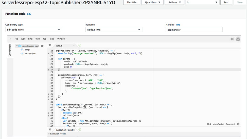
The TopicPublisher Lambda function is invoked by the API Gateway endpoint and publishes to the AWS IoT topic esp32/sub.
1. On the application page, find the Application endpoint.
2. To test that the TopicPublisher function is working, enter the following into a terminal or command-line utility, replacing ENDPOINT with the URL from above.
curl -d '{"text":"Hello world!"}' -H "Content-Type: application/json" -X POST https://ENDPOINT/publishUpon success, the request returns a copy of the message.

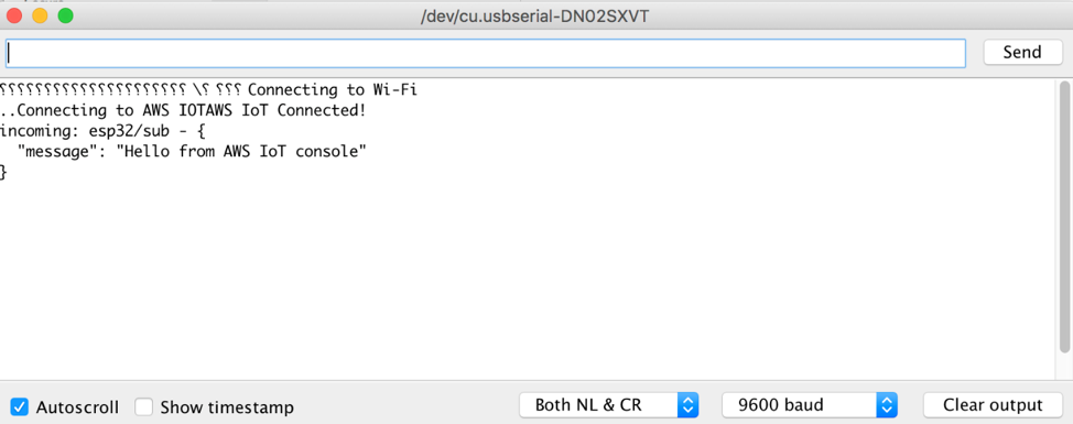
Back in the Serial Monitor, the message published to the topic esp32/sub prints out.
Creating an IoT thermal printer
With the completion of the previous steps, the ESP32 device currently logs incoming messages to the serial console.
The following steps demonstrate how the code can be modified to use incoming messages to interact with a peripheral component. This is done by wiring a thermal printer to the ESP32 in order to physically print messages. The REST endpoint from the previous section can be used as a webhook in third-party applications to interact with this device.

A wiring diagram depicting an ESP32 connected to a thermal printer.
- Follow the product instructions for powering, wiring, and installing the correct Arduino library.
- Ensure that the thermal printer is working by holding the power button on the printer while connecting the power. A sample receipt prints. On that receipt, the default baud rate is specified as either 9600 or 19200.

- In the Arduino code from earlier, include the following lines at the top of the main sketch file. The second line defines what interface the thermal printer is connected to. &Serial2 is used to set the third hardware serial interface on the ESP32. For this example, the pins on the Sparkfun ESP32 Thing, GPIO16/GPIO17, are used for RX/TX respectively.
#include "Adafruit_Thermal.h" Adafruit_Thermal printer(&Serial2); - Replace the
setup()function with the following to initialize the printer on device bootup. Change the baud rate ofSerial2.begin()to match what is specified in the test print. The default is 19200.void setup() { Serial.begin(9600); // Start the thermal printer Serial2.begin(19200); printer.begin(); printer.setSize('S'); connectAWS(); } - Replace the
messageHandler()function with the following. On any incoming message, it parses the JSON and prints the message on the thermal printer.void messageHandler(String &topic, String &payload) { Serial.println("incoming: " + topic + " - " + payload); // deserialize json StaticJsonDocument<200> doc; deserializeJson(doc, payload); String message = doc["message"]; // Print the message on the thermal printer printer.println(message); printer.feed(2); } - Choose Upload.
- After the firmware has successfully uploaded, open the Serial Monitor to confirm that the board has connected to AWS IoT.
- Enter the following into a command-line utility, replacing ENDPOINT, as in the previous section.
curl -d '{"message": "Hello World!"}' -H "Content-Type: application/json" -X POST https://ENDPOINT/publish

If successful, the device prints out the message “Hello World” from the attached thermal printer. This is a fully serverless IoT printer that can be triggered remotely from a webhook. As an example, this can be used with GitHub Webhooks to print a physical readout of events.
Conclusion
Using a simple Arduino sketch, an AWS Serverless Application Repository application, and a microcontroller, this post demonstrated how to build a basic serverless workflow for communicating with a physical device. It also showed how to expand that into an IoT thermal printer with real-world applications.
With the use of AWS serverless, advanced compute and extensibility can be added to an IoT device, from machine learning to translation services and beyond. By using the Arduino programming environment, the vast collection of open-source libraries, projects, and code examples open up a world of possibilities. The next step is to explore what can be done with an Arduino and the capabilities of AWS serverless. The sample Arduino code for this project and more can be found at this GitHub repository.