Containers
Use Raspberry Pi 5 as Amazon EKS Hybrid Nodes for edge workloads
Since its launch, Amazon Elastic Kubernetes Service (Amazon EKS) has powered tens of millions of clusters so that users can accelerate application deployment, optimize costs, and use the flexibility of Amazon Web Services (AWS) for hosting containerized applications. Amazon EKS eliminates the operational complexities of maintaining Kubernetes control plane infrastructure, while offering seamless integration with AWS resources and infrastructure.
However, some workloads need to be run at the edge with real-time processing, such as latency-sensitive applications that generate large volumes of data.
In these scenarios, when there is consistent internet connectivity available, users often seek the benefits of cloud integrations while continuing to use their on-premises hardware. That’s why we introduced Amazon EKS Hybrid Nodes at AWS re:Invent 2024, so that users can extend their Kubernetes data plane to the edge while continuing to run the Kubernetes control plane in an AWS Region. Amazon EKS Hybrid Nodes unifies Kubernetes management across cloud, on-premises, and edge environments by enabling users to use their on-premises infrastructure as nodes in EKS clusters, alongside Amazon Elastic Compute Cloud (Amazon EC2).
To demonstrate the use of Amazon EKS Hybrid Nodes, we explored a practical use case from the manufacturing sector. These environments often rely on real-time data from digital sensors that must be processed locally due to latency and reliability, while still using the cloud for analytics and long-term storage.
Our use case involves reading distance values from an ultrasonic sensor, processing them on a local edge device running as a Hybrid Node, and storing them in Amazon DynamoDB on AWS.
In this post, we demonstrate how to implement Amazon EKS Hybrid Nodes using the Raspberry Pi 5, a popular edge computing platform. We cover the following:
- Setting up an EKS cluster that seamlessly connects cloud and edge infrastructure
- Securing connectivity using the WireGuard VPN for site-to-site communication
- Enabling container networking with Cilium for hybrid node deployments
- Demonstrating a real-world Internet of Things (IoT) application that demonstrates the power of edge-cloud integration
Why Raspberry Pi 5?
The Raspberry Pi 5 is compact and can be deployed at the edge so that you can process data before it is transmitted to the cloud. Building on this strength, we created a microservices-based application partly running on the edge on a Raspberry Pi 5 and partly on AWS in the cloud. On the edge, a local Raspberry Pi is connected to an ultrasonic sensor ingesting real-time distance data. This data is processed and uploaded to a DynamoDB database. Then, the data is visualized through a dashboard that runs as a separate deployment in the cluster. With this implementation, you can pre-process the data locally to reduce the amount of data sent to AWS.
Architectural overview
In the cloud, we deploy an Amazon Virtual Private Cloud (Amazon VPC) that hosts the EKS cluster. Within this VPC, an EC2 instance acts as a gateway between the cloud environment and the on-premises edge network. This EC2 instance establishes a secure site-to-site VPN tunnel, using WireGuard, to the Raspberry Pi 5, which serves as our hybrid node. When the tunnel is established, traffic between the Raspberry Pi and the cloud is routed through the Wireguard Server running on Amazon EC2, extending the EKS cluster to the edge. From the cluster’s perspective, the Raspberry Pi behaves just like any other node, despite being located outside the VPC. The resulting architecture looks like the following figure.
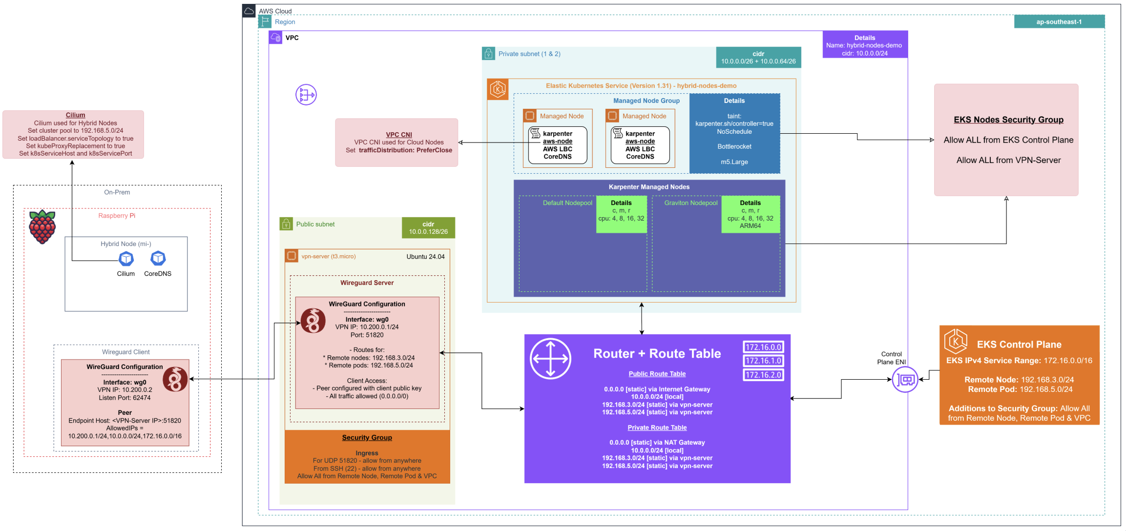
The managed Kubernetes control plane runs on AWS, providing the API server, etcd datastore, scheduler, and controller manager. In this walkthrough, we configure the Kubernetes control plane with public endpoint access, allowing our Raspberry Pi nodes to communicate with it over the internet. AWS handles the operational complexity of securing and scaling the Kubernetes control plane for high availability, while you focus on your applications.
We run a dedicated EC2 instance with WireGuard, which serves as a VPN gateway, creating a secure tunnel between AWS and our edge infrastructure. This server acts as the hub in a hub-and-spoke topology, enabling communication between the Amazon EKS control plane and our Raspberry Pi nodes for kubectl exec commands, log retrieval, and webhook operations.
Our Raspberry Pi devices run the standard Kubernetes node components (kubelet, kube-proxy, and container runtime) along with the Amazon EKS Hybrid Nodes CLI tool (nodeadm). These nodes register with the EKS cluster through AWS Systems Manager, appearing as standard worker nodes in your cluster despite running on user-managed hardware.
Our Raspberry Pi nodes initiate connections to the Amazon EKS control plane through the public internet. This includes API server communication for node registration, pod status updates, and resource requests. The public endpoint approach streamlines connectivity while maintaining security through AWS Identity and Access Management (IAM) authentication and TLS encryption.
Getting started
To bridge the network between the Raspberry Pi and the EKS cluster running in the cloud, we start by configuring a lightweight WireGuard server on an EC2 instance. This server functions solely as a network gateway, thus a cost-efficient t4g.nano instance is sufficient for most use cases. When that’s up and running, we install the WireGuard client on the Raspberry Pi to establish a persistent connection and configure the appropriate routing to allow traffic between the Raspberry Pi and the VPC used by the EKS cluster. Then, we add the hybrid node to the cluster, configure the CNI, and install the application.
Requirements:
- Raspberry Pi 5, running Ubuntu 24.10, with SSH enabled
- Wired Ethernet connection (recommended for stability)
- AWS Command Line Interface (AWS CLI)
- kubectl
- Helm
Step 1: Create the EKS cluster
Begin by creating an Amazon VPC in your chosen AWS Region, with at least one public and one private subnet. These subnets host your cloud worker nodes and the network interfaces needed for control plane communication. When setting up your EKS cluster, make sure that remote networking parameters are set to enable your control plane to reach your hybrid nodes and pods outside of the VPC.
To streamline this setup, we’ve made available a set of Terraform templates on the AWS Samples GitHub repository. These templates automate much of the network and Amazon EKS configuration, such as enabling hybrid networking and preparing the necessary IAM and CNI policies.
If you’re new to Amazon EKS Hybrid Nodes or want a deeper dive into the configuration process, then refer to the official AWS documentation for enabling EKS clusters for Amazon EKS Hybrid Nodes.
Step 2: Set up the VPN server
Amazon EKS Hybrid Nodes need both a stable connection and a private network between your on-premises/edge environment and your VPC. This necessitates setting up a VPN or similar secure, private networking solution. There are several documented options available such as AWS Site-to-Site VPN, AWS Direct Connect, or your own VPN connection. Here we use WireGuard, which is open source software for fast and secure VPN connections.
2.1 Installing Wireguard
We set up Wireguard by installing the server on an EC2 instance running in our AWS account. You can use any standard Wireguard installation guide to configure the server on your EC2 instance, making sure to open port UDP/51820 from your local IP to the EC2 instance’s security group. Get started by installing Wireguard through APT.
2.2 Create the Wireguard configuration
Then, with the editor of your choice, add the following configuration, replacing the placeholders with the Public Key and Private Key of your Wireguard server.
Add the following configuration (replace placeholders):
Then, enable the Wireguard service, and verify that the connection is established with the Amazon EC2 server.
You should see something similar to the following:
As a first step for networking, we must enable IPv4 forwarding on the instance so that it can route packets between network interfaces:
Then, to allow your EC2 instance to forward traffic between the Wireguard network and your VPC, configure iptables to perform Network Address Translation (NAT) and allow packet forwarding.
The first command tells the kernel to rewrite the source IP of packets leaving via through the Wireguard interface (wg0) to the EC2 instance’s IP, which is essential for return traffic routing. The second rule allows packets from the VPC interface (eth0) to be forwarded to Wireguard. The third rule allows return traffic from Wireguard back into the VPC, but only for connections that were already established.
Then, to ensure make sure that these rules persist across reboots, install and configure iptables-persistent:
This saves your current rules to /etc/iptables/rules.v4 and /etc/iptables/rules.v6 and ensures makes sure that they’re applied automatically on every reboot.
As a final step, make sure to disable the source/destination check of the traffic flowing through the instance’s interface. By default, AWS enables source/destination checking to ensure that an instance only processes traffic explicitly addressed to or from itself. However, since our instance is acting as a gateway, routing packets on behalf of other devices on our network, we need to disable this restriction.
Add the Raspberry Pi to the cluster as a remote node
With networking configured and the EKS cluster created, the next step is to join the node to the cluster so Kubernetes can begin scheduling pods on it.
First, make sure that the node can authenticate to the cluster. Amazon EKS Hybrid Nodes authenticate to the EKS cluster using IAM, thus we need to assign IAM roles to on-premises machines. This necessitates setting up an authentication mechanism using either Systems Manager or IAM Roles Anywhere. The GitHub guide specifically uses Systems Manager Hybrid Activations for this purpose. You can follow this guide to create the necessary AmazonEKSHybridNodesRole with either one of the two options. Then, you can register the node using nodeadm. Follow the instructions provided in the guide, and make sure to specify the role that you created during the previous step.
Setting up the Container Network Interface
After the EKS cluster and hybrid nodes have been created and configured successfully, our node still shows a Not Ready status. This is because the Container Network Interface (CNI) has not been installed. The CNI is a crucial component responsible for setting up network interfaces inside of containers, assigning IP addresses, and configuring routing so that pods can communicate seamlessly within the cluster and with external networks. Without a CNI, Kubernetes nodes cannot provide the necessary network connectivity for pods, thus preventing workload deployment. We must install a CNI before the hybrid nodes become ready. Cilium is an open source, cloud native solution for providing, securing, and observing network connectivity between workloads, which is officially supported for Amazon EKS Hybrid Nodes.
Step 1: Install Cilium
After installing Helm, we add the Cilium Helm chart and install Cilium into our EKS cluster.
Create cilium-values.yaml:
Then we can install Cilium using Helm:
You have successfully installed Cilium, now wait until both pods are ready:
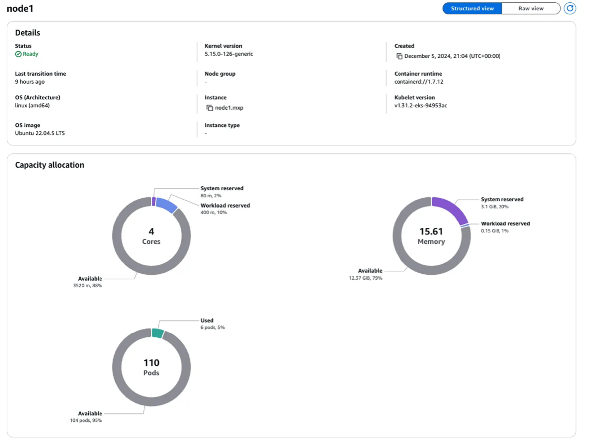
Step 2: Verify that hybrid nodes are running
We can check if all our nodes are running successfully in our EKS cluster.We can check the node status:
The node is now marked Ready.
When our cluster is up and running, and the container networking works as expected, we should see the node in a Ready state on the Amazon EKS Node Overview Dashboard, as shown in the following figure.
Deploying a sample application on Amazon EKS Hybrid Nodes with edge integration
The application consists of two Kubernetes deployments:
- Ultrasonic: Reads measurements from the ultrasonic sensor and writes them to DynamoDB.
- Dashboard: Reads data from DynamoDB and presents it in an interactive UI.
We use an HC-SR04 ultrasonic sensor, which emits sound waves and measures the time it takes for the echo to return to compute distance. This type of sensor is common in the manufacturing and automotive sectors, for example:
- Detecting the presence or absence of objects on assembly lines
- Measuring fluid levels in containers
- Monitoring parking spot availability
In a more advanced setup, this pipeline could be extended to run object detection models locally and trigger events (for example publish to an Amazon Simple Queue Service (Amazon SQS) queue) based on detected conditions.
However, in this demo we prioritized clarity. We use the node to detect the distance of an object placed in front of Raspberry Pi and push this value to a DynamoDB table every 10s.
Step 1: Hardware requirements and setup
HC-SR04 Ultrasonic Sensor:
- 1kΩ and 2kΩ Resistors (used in a voltage divider circuit)
- Jumper Wires
- Breadboard
We use a breadboard for rapid, solder-free prototyping. It streamlines wiring, supports quick iteration, and allows the HC-SR04 sensor to stand vertically for optimal placement. Each row on the breadboard’s terminal strip shares electrical continuity, which streamlines connections.
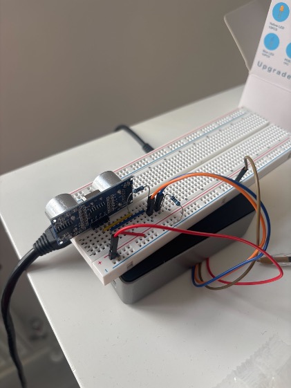
Connecting the HC-SR04 to Raspberry Pi GPIO
Connect the Raspberry Pi’s 3.3V and GND pins to the breadboard’s power rails.
Insert the HC-SR04 sensor into the breadboard. Then connect:
VCC→ Breadboard + rail (red wire)GND→ Breadboard – rail (black wire)TRIG→ Raspberry Pi GPIO 4 (orange wire)ECHO→ Voltage divider → GPIO 17 (blue wire)
The voltage divider—created using 1kΩ and 2kΩ resistors in series, reduces the 5V output from the sensor’s ECHO pin to a safe ~3.3V level for the Raspberry Pi’s GPIO input.
The following diagram is included to clarify this layout.
This GPIO mapping can later be abstracted and managed dynamically through Kubernetes ConfigMaps. This allows for flexibility in how the application handles hardware configuration across different deployments. We cover that in a later section.
Step 2: Deploy the DynamoDB table
We store data in a DynamoDB table named eks-timeseries, created in the eu-west-1 Region. We use the following schema:
- Partition Key:
yyyymmdd - Sort Key:
hhmmss
This schema enables efficient time-based queries and aligns with typical time series patterns, where data is retrieved per day and sorted by timestamp.
AWS CloudFormation template:
Step 3: Deploy the sensor application
In the GitHub repository, there is an examples directory containing a project named ultrasonic-demo. This folder includes:
- Kubernetes manifest files
- Python source code
- A Dockerfile to build your container image
Start by building the Docker image from the ultrasonic-demo directory and pushing it to your container registry, such as Amazon Elastic Container Registry (Amazon ECR).
Pay attention to the ConfigMap section in the manifest. It defines the environment variables that the Python script expects to find to access the GPIO and DynamoDB, and configures the AWS CLI.
To deploy the application, run:
After deployment, verify that the ultrasonic-sensor pod is running:
Then, inspect the logs to monitor sensor output and DynamoDB writes:
You should see the distances on the logs, and the same results should be visible on DynamoDB.

Step 4: Deploy the frontend dashboard
To visualize the sensor readings, we built a frontend dashboard that queries data directly from DynamoDB and displays it as a live-updating chart.
Any authenticated data consumer, even external applications, can query DynamoDB directly.
We like all of our applications to be containerized, thus we decided to deploy the dashboard through a deployment in our cluster.
Review the frontend and directory in the repository.
Build the Docker image for the frontend and push it to your container registry, as you did for the backend. Then, update the provided Kubernetes manifest.
To deploy the application, run:
Then, you can port-forward the service locally:
Access the dashboard from your browser by navigating to http://localhost:8080.
You should see a live chart updating with real-time distance readings, retrieved directly from your DynamoDB table.

Conclusion
And that’s a wrap! You’ve just turned a Raspberry Pi 5 into a node of an Amazon EKS cluster, running outside an Amazon VPC, reading real-world sensor data through GPIO, and pushing it securely to the cloud using Amazon DynamoDB. We hope that what we demonstrated here with a Raspberry Pi could serve as a practical demo of how hybrid Kubernetes architectures can bridge physical environments and the cloud: whether you’re working with sensors in a factory, servers in a retail store, or inference engines in a hospital or trading floor. For organizations looking to modernize distributed infrastructure, Amazon EKS Hybrid Nodes offer a pragmatic path forward. You can build once and run in the cloud, at the edge, or on your own bare metal. With the flexibility and power of this approach, now is an excellent time to start your proof of concept and explore the possibilities for your organization.
Want to try this yourself? Check out the GitHub repo, clone the example, and start building. Furthermore, have a look to our official guide on Amazon EKS Hybrid Nodes, and reach out to your AWS account team with questions as you get started.
About the authors
 Alberto Crescini is an Enterprise Solutions Architect at AWS, helping United Kingdom’s Energy and Utilities companies build infrastructure for the energy transition. He supports customers working on projects such as grid balancing and flexible generation, guiding them to modernize their systems and hyperscale platforms through the AWS Containers focus area.
 Utkarsh Pundir is a Containers Specialist Solutions Architect at AWS, where he works on helping customers build solutions on EKS. His focus areas include hybrid architecture and implementing Generative AI workloads on EKS as part of AWS’s go-to-market initiatives.
 Gladwin Neo is a Containers Specialist Solutions Architect at AWS, where he helps customers migrate and modernize their workloads to deploy them on Amazon Elastic Kubernetes Service (EKS) or Amazon Elastic Containers Service (ECS).