AWS for Industries
From Connected to Resilient: Cloud-Native Payment Connectivity on AWS
Financial institutions are increasingly adopting connectivity models built for the cloud to achieve resilient payment connectivity with payment networks and Financial Market Infrastructures (FMIs). But what happens when a persistent payment session drops silently during an off-peak window, or a backend deployment severs thousands of active authorization channels? These are the operational realities that standard connectivity patterns do not address.
We have seen payment platform teams discover these gaps only after production incidents: a reconnection storm at market open after overnight idle timeouts, or a rolling deployment that triggered duplicate authorizations across an entire card network channel. The patterns in this post address these scenarios directly. In a recent post, AWS Cloud Connectivity Patterns for Financial Market Infrastructures, we introduced four connectivity patterns spanning customer-managed infrastructure to fully cloud architectures. Patterns 3 (AWS PrivateLink) and 4 (VPC Resource Gateway) remove the need for customers to manage hybrid networking constructs such as AWS Transit Gateway, AWS Direct Connect Gateway, or physical routers.
Payment connectivity spans a spectrum of protocol models. Modern payment platforms, particularly those built on ISO 20022 or RESTful APIs, use short-lived request/response connections with built-in retry and idempotency, and standard AWS PrivateLink and Resource Gateway configurations serve these workloads well. However, the card networks and national debit rails that carry most global real-time authorization volume operate on persistent-session protocols such as ISO 8583. A single Transmission Control Protocol (TCP) connection remains open for hours or days, carrying sequential transaction messages.
These long-lived sessions introduce distinct operational considerations: connection lifecycle management during off-peak windows, session continuity during backend maintenance, tenant-level traffic isolation in multi-tenant deployments, and proactive health monitoring for FMI-initiated data flows.
In this post, we present four production-hardening patterns (A-D) that extend Patterns 3 and 4 for payment workloads operating persistent session-based protocols. These patterns optimize connection reliability, maintenance workflows, tenant isolation, and observability at the infrastructure layer, benefiting organizations connecting to traditional payment rails through AWS PrivateLink and Resource Gateway.
Prerequisites
Before proceeding, we assume familiarity with the connectivity patterns described in the AWS Cloud Connectivity Patterns for Financial Market Infrastructures post, and AWS networking services including Amazon VPC, AWS PrivateLink, Network Load Balancer, Amazon EC2 Auto Scaling, and Amazon VPC Lattice.
Solution Overview
The four hardening patterns layer onto the foundational PrivateLink (Pattern 3) and Resource Gateway (Pattern 4) connectivity. Patterns A through C harden the AWS PrivateLink path (Pattern 3 → A, B, C) where customers start connectivity toward FMI-hosted services. Pattern D hardens the Resource Gateway path (Pattern 4 → D) where FMIs start data pulls from participant environments.
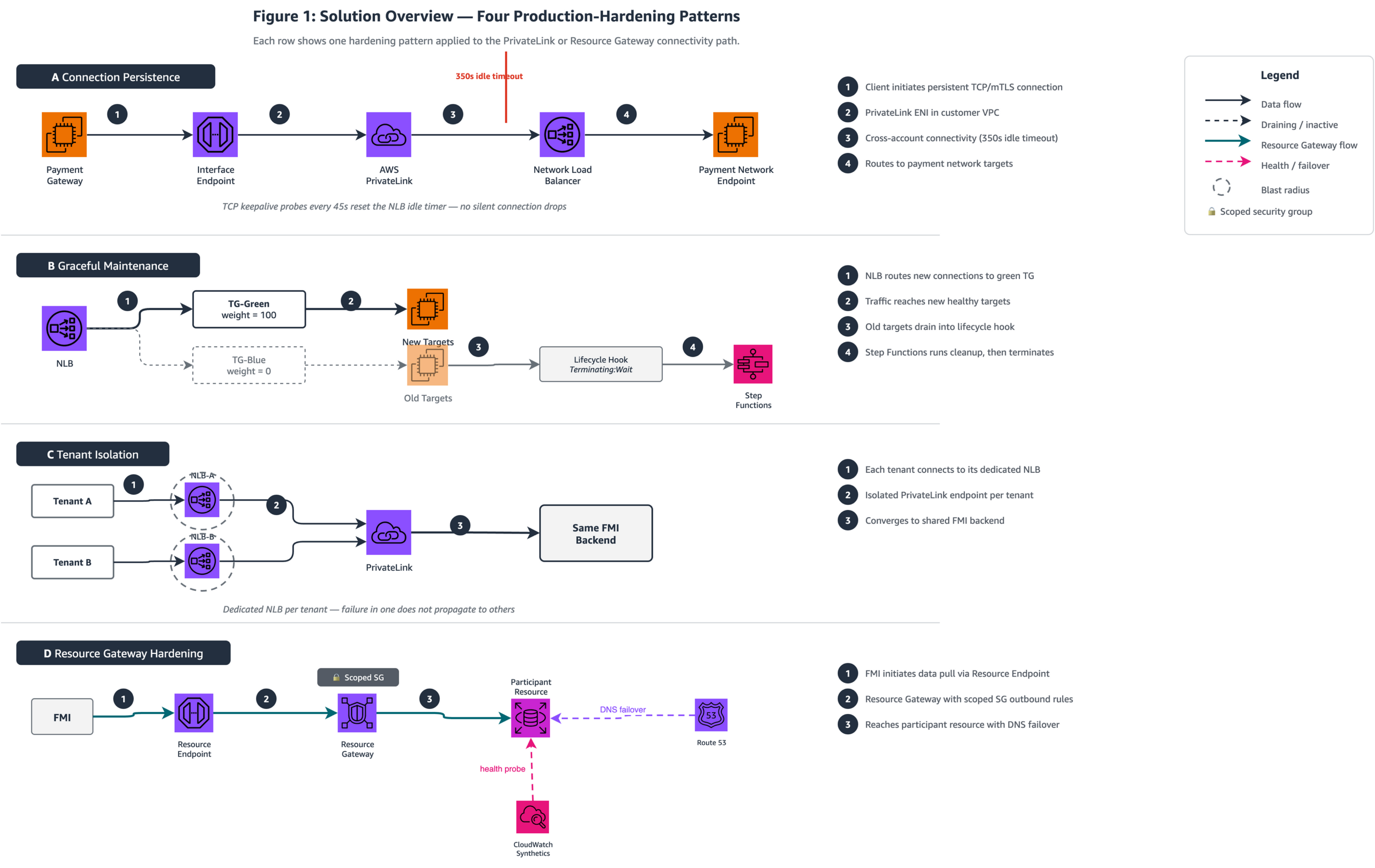
Figure 1: Solution Overview — The two horizontal lanes represent the foundational connectivity paths from the AWS FMI blog. The top lane shows the customer-initiated AWS PrivateLink path (Pattern 3) hardened by Patterns A, B, and C. The bottom lane shows the FMI-initiated Resource Gateway path (Pattern 4) hardened by Pattern D.
Table 1: Pattern Selection Guide
Architects should apply Pattern A as a universal baseline, then layer Patterns B through D based on operational maturity, tenant model, and requirements.
| Pattern | Operational Consideration | When to Apply | When NOT to Apply | Effort | Dependencies |
|---|---|---|---|---|---|
| A – Connection Persistence | Connection lifecycle management across Network Load Balancer (NLB) idle timeout (350s Transport Layer Security (TLS) / configurable TCP) | Persistent-session protocols (such as ISO 8583) traversing NLB-backed AWS PrivateLink | REST/HTTP payment APIs (ISO 20022 over HTTPS) using short-lived request/response connections | Low: sysctl config only, no code changes | None: universal baseline |
| B – Graceful Maintenance | Session continuity during backend deployments, patching, or certificate rotation | Long-lived mutual TLS (mTLS)/TCP sessions requiring uninterrupted connectivity | Stateless HTTP services with built-in retry and idempotency | Medium: requires AWS Step Functions or AWS CodeDeploy automation | Pattern A recommended as baseline |
| C – Tenant-Level Inbound Isolation | Tenant-level traffic isolation on shared infrastructure | Multi-tenant platforms serving external payment network participants (acquirers, issuers, processors) | Fewer than five tenants with similar traffic profiles where cost multiplication is unjustified | Medium: NLB-per-tenant deployment, quota planning | None: independent of A and B |
| D – Resource Gateway Hardening | Proactive health monitoring and scoped access controls for FMI-initiated data pulls | FMIs pulling reconciliation data, settlement files, or regulatory reports through Resource Gateway | Simple file transfers where basic S3 access controls suffice | Medium: external monitoring + scoped security groups | None: applies to Pattern 4 path only |
Pattern A – Connection Persistence for Persistent Payment Sessions
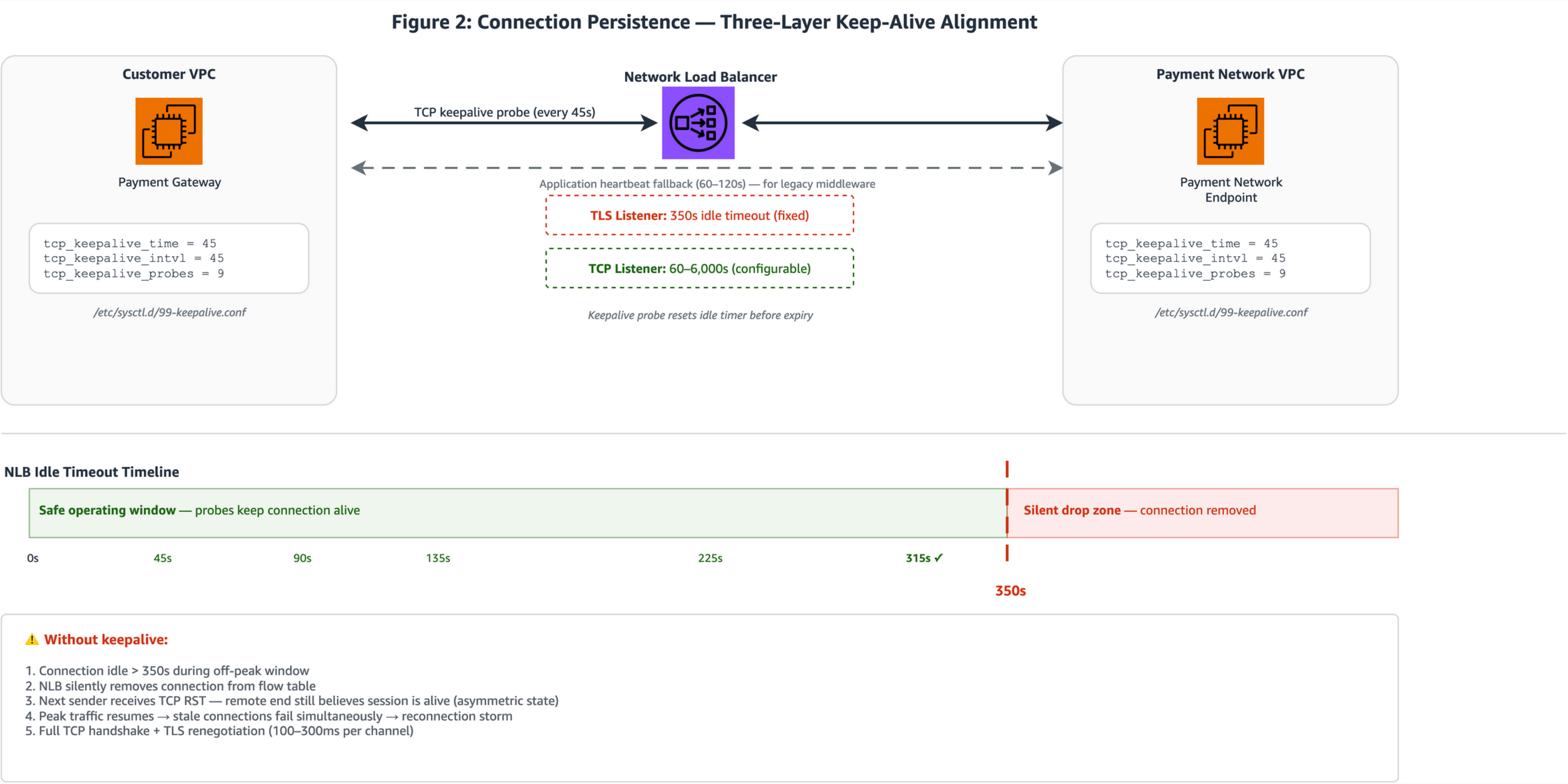
Figure 2: Three-layer connection persistence showing (left) client payment gateway instances with sysctl keepalive probes at 45-second intervals, (center) NLB TLS listener with the 350-second idle timeout boundary annotated, and (right) payment network endpoint target instances. The timeline bar shows probe timing relative to the 350s boundary.
- ISO 8583 payment protocols hold TCP connections open for hours or days between payment terminals, processors, and payment network endpoints. During off-peak windows (overnight batch gaps, weekend lulls, or between authorization bursts) these connections sit idle. The NLB idle timeout is 350 seconds for TLS listeners (fixed) and configurable from 60 to 6,000 seconds for TCP listeners (available since September 2024). When this timeout expires, the NLB sends a TCP RST to both client and target, forcibly closing the connection. For payment workloads, this RST is critical to understand: if it arrives at mid-transaction, the client may retry without an idempotency key, potentially triggering duplicate authorizations. Aligning keepalive probes to fire well before this timeout helps avoid full TCP handshake plus TLS renegotiation (100–300 ms per channel) when traffic resumes.
- Linux TCP keepalive parameters on both client and target instances generate periodic probe traffic well below the 350-second threshold. Setting
tcp_keepalive_time=45,tcp_keepalive_intvl=45, andtcp_keepalive_probes=3by using sysctl results in the kernel sending a keepalive probe after 45 seconds of idle time and repeat every 45 seconds. For NLB timeout prevention, only the first probe at 45 seconds matters; it resets the NLB idle timer before it expires. The probes parameter controls dead-peer detection timing, not NLB keep-alive. Withprobes=3, the kernel declares the peer dead after 45 + (45×3) = 180 seconds of unacknowledged probes. This supports faster detection of failed endpoints compared toprobes=9, which delays dead-peer detection to 450 seconds. Operators should align the probe count with their specific payment network’s keepalive expectations; some card networks tolerate multi-minute silence during network-side maintenance, in which case a higher probe count avoids premature reconnection. Apply these settings persistently through/etc/sysctl.d/99-keepalive.confon both payment gateway client instances and backend payment network endpoint targets. - For TCP listeners (not TLS), increase the configurable idle timeout to match the expected maximum idle gap plus a safety margin (for example, 900 seconds for settlement batch windows). For TLS listeners, the timeout remains fixed at 350 seconds, so workloads terminating TLS at the NLB should rely on keepalive probes rather than timeout adjustment.
- For payment stacks that cannot use
SO_KEEPALIVE, such as legacy ISO 8583 gateways running on middleware that does not expose socket options, application-level heartbeat messages serve as an alternative. A lightweight echo or network-management message sent every 60–120 seconds keeps the connection active from the NLB’s perspective. The goal is to verify that at least one layer (OS keepalive, NLB timeout extension, or application heartbeat) generates traffic within the idle window. OS-level keepalive is the preferred default because it requires no application code changes.
Important: The NLB idle timeout for TLS listeners is fixed at 350 seconds. Only TCP listeners support the 60–6,000 second configurable range. For workloads terminating TLS at the NLB, keepalive probes are the recommended approach.
Apply this pattern when persistent-session payment protocols traverse an NLB-backed AWS PrivateLink endpoint service, particularly when idle gaps during off-peak periods exceed 60 seconds. This also helps reduce the idempotency risk of replayed authorization requests during reconnection. The NLB RST can arrive without warning, clients without idempotency keys may unknowingly replay the last in-flight message. The tradeoff is a small amount of additional probe traffic. This is negligible for payment workloads but worth accounting for in environments with thousands of persistent connections. For connection-pooled architectures (such as payment gateways built on Netty or similar frameworks maintaining multiple persistent connections), apply these keepalive settings per pool member.
With persistent connections now maintained across idle windows, the next consideration is maintenance: how do you replace backend targets without dropping active sessions?
Pattern B – Graceful Maintenance with Lifecycle Hooks and Weighted Target Groups
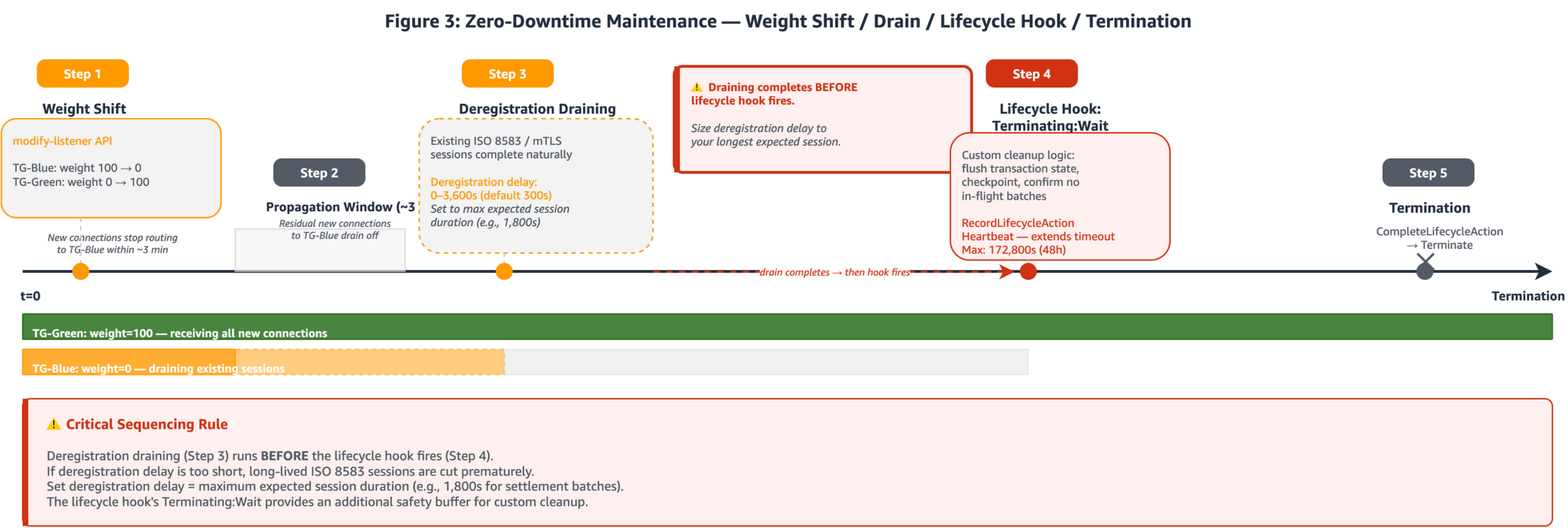
Figure 3: Zero-downtime maintenance operational timeline: (Step 1) Blue target group weight set to 0 by using the modify-listener API. (Step 2) Propagation window as residual connections drain. (Step 3) Deregistration draining: existing sessions complete naturally. (Step 4) EC2 Auto Scaling lifecycle hook in Terminating:Wait state. (Step 5) CompleteLifecycleAction called, termination proceeds. TG-Green/TG-Blue swimlane bars show target group status over time.
Payment backends behind AWS PrivateLink carry stateful mTLS/TCP sessions where a single connection may process hundreds of sequential authorization messages. NLB weighted target groups support zero-downtime maintenance by assigning numeric weights (0–999) to each target group. The critical behavior: weights apply only to new connections. Existing connections remain pinned to targets in the original target group for up to one hour if traffic is being sent, or until the idle timeout elapses. This connection-pinning behavior supports the use of weighted target groups for stateful payment sessions.
For planned deployments (blue-green through weight shift)
- Deploy new instances into the green target group and verify health checks pass. Then set the blue target group weight to 0 by using the
modify-listenerAPI withForwardConfig.TargetGroups. The NLB stops routing new connections to the blue group within approximately three minutes, while existing long-lived ISO 8583 or mTLS sessions continue uninterrupted on blue targets. - For canary deployments of payment protocol changes, such as EMV 3DS version upgrades, hold weights at 95/5 or 90/10 for an extended observation window, monitoring error rates on the canary target group before proceeding.
- Once all existing connections on the blue group have drained naturally (or the deregistration delay expires), deregister blue targets and terminate.
For unplanned scale-in (Auto Scaling lifecycle hooks)
- When EC2 Auto Scaling scales in, it first deregisters the terminating instance from the load balancer. Connection draining runs during this phase. The deregistration delay defaults to 300 seconds and is configurable up to 3,600 seconds. For payment backends carrying long-lived mTLS sessions, set this value to the maximum expected session duration (for example, 1,800 seconds for 30-minute settlement batch windows). Only after deregistration completes does the lifecycle hook place the instance into
Terminating:Wait. - The lifecycle hook’s default wait state is one hour (with a default
HeartbeatTimeoutof 3,600 seconds). CallingRecordLifecycleActionHeartbeatextends the timeout by theHeartbeatTimeoutvalue each time, up to a maximum of the lesser of 172,800 seconds (48 hours) or 100 times theHeartbeatTimeout. With the defaultHeartbeatTimeoutof 3,600 seconds, the effective maximum is 172,800 seconds. If you set a shorterHeartbeatTimeout(for example, 300 seconds), the effective maximum reduces to 30,000 seconds (~8.3 hours). During this wait state, run custom cleanup logic: flush transaction state, checkpoint, and confirm no in-flight settlement batches remain. When cleanup completes, callCompleteLifecycleActionto proceed to termination.
Important sequencing: Deregistration draining completes before the lifecycle hook fires. Size the deregistration delay (0–3,600s) to your longest expected session duration. The lifecycle hook wait state provides an additional cleanup window after draining finishes. The effective maximum wait is the lesser of 172,800 seconds or 100× your configured HeartbeatTimeout.
Apply this pattern for scheduled or automated maintenance of payment backends carrying stateful TCP/mTLS sessions. The tradeoff is operational complexity: the weight-shift and lifecycle-hook sequence requires automation (through AWS Step Functions or AWS CodeDeploy hooks) and monitoring to confirm draining completes before lifecycle timeouts expire.
Patterns A and B address operational considerations within a single tenant’s connection path. What happens when multiple external tenants share the same inbound infrastructure?
Pattern C – Tenant-Level Inbound Isolation Through Dedicated NLBs
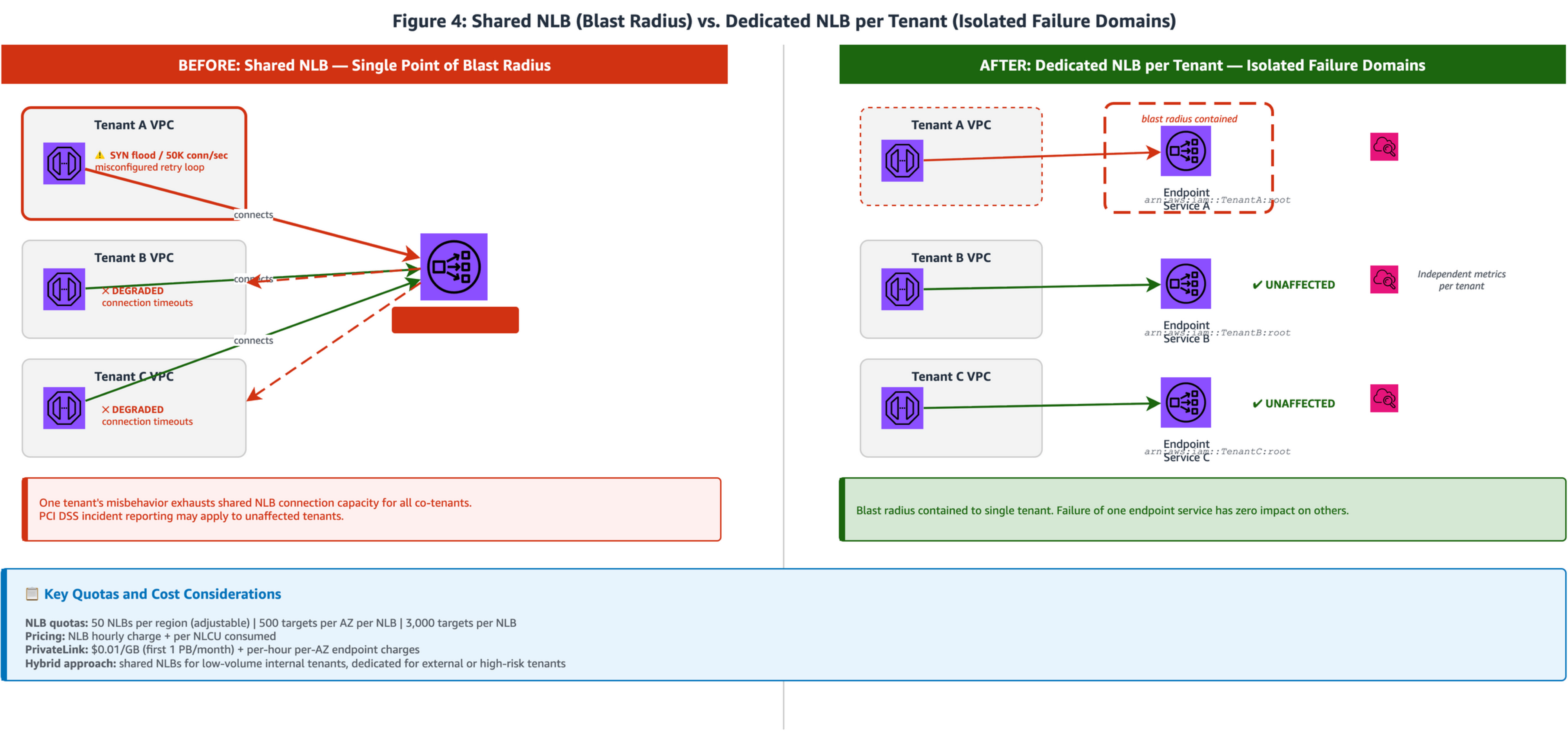
Figure 4: Side-by-side comparison. Left panel (Shared NLB): multiple tenant VPCs connecting to a single shared NLB where all tenants share capacity. Right panel (Dedicated NLBs): each tenant connects through its own Interface Endpoint to a dedicated NLB registered as a separate AWS PrivateLink endpoint service, providing independent capacity and monitoring per tenant.
- In a shared NLB architecture, traffic from multiple payment tenants (acquirers, issuers, payment processors) converges on a single Network Load Balancer. While PrivateLink provides network-level isolation between consumer VPCs, the NLB operates at Layer 4 and serves all connected tenants from a shared capacity pool. The AWS PrivateLink multi-tenant SaaS reference architecture notes that traffic is isolated from other customers “with the exception of the AWS PrivateLink, NLB, and ALB components”, making the NLB layer the right place to add tenant-level isolation for payment workloads requiring independent capacity guarantees.
- Deploy a dedicated NLB for each payment tenant, with each NLB registered as a separate AWS PrivateLink endpoint service. Scope each endpoint service with its own allowlist of AWS principals, restricting endpoint creation to the specific tenant’s account ARN (for example,
arn:aws:iam::account_id:root). This provides connection-level isolation: each tenant operates within its own NLB capacity, and per-tenant NLBs yield independent Amazon CloudWatch metrics without tag-based filtering, simplifying capacity planning and incident response.
Why dedicated NLBs rather than security groups alone? NLBs gained security group support in August 2023, enabling access control (who can connect) at the NLB layer. However, security groups and dedicated NLBs serve different purposes: security groups control access (restricting which IPs and ports can reach the NLB), while dedicated NLBs provide capacity isolation (independent scaling, independent metrics, independent failure scope). For payment workloads requiring both access control and capacity guarantees, use security groups on dedicated per-tenant NLBs.
- Quotas: Review NLB quotas and AWS PrivateLink quotas before sizing your dedicated-NLB deployment. Key constraints include NLBs per Region (default 50, adjustable), targets per Availability Zone, and per-endpoint bandwidth (10 Gbps per AZ by default, scaling to 100 Gbps). With cross-zone load balancing active, the target maximum reduces to 500 per load balancer and cross-AZ data transfer charges apply.
Table 2: Cost Estimation — Shared vs. Dedicated NLB Model
The following table provides directional cost estimates for comparing shared and dedicated NLB architectures. Actual costs depend on traffic volume, NLCU consumption, and AZ deployment choices.
| Component | 5 Tenants (Dedicated) | 10 Tenants (Dedicated) | 50 Tenants (Dedicated) | Shared (1 NLB) |
|---|---|---|---|---|
| NLB hourly (USD 0.0225/hr × NLBs × 730 hrs/mo) | USD 82.13 | USD 164.25 | USD 821.25 | USD 16.43 |
| AWS PrivateLink endpoint per-AZ (USD 0.01/hr × endpoints × AZs × 730 hrs/mo) | USD 109.50 (5 endpoints × 3 AZs) | USD 219.00 (10 × 3) | USD 1,095.00 (50 × 3) | USD 21.90 (1 × 3) |
| AWS PrivateLink data processing (USD 0.01/GB, first 1 PB) | Same across models, depends on total traffic volume | Same | Same | Same |
| NLCU charges (per NLB) | Per-tenant NLCU tracked independently | Per-tenant | Per-tenant | Shared across all tenants |
| Approximate monthly fixed cost | ~USD 192 | ~USD 383 | ~USD 1,916 | ~USD 38 |
Note: NLCU charges are usage-based and vary by traffic pattern. The dedicated model provides per-tenant NLCU visibility but total NLCU cost is similar for equivalent aggregate traffic. Quota increase required beyond 50 NLBs per Region.
- The dedicated-NLB model increases NLB hourly costs linearly with tenant count and consumes the 50-NLB default Region quota, requiring quota increases beyond approximately 50 tenants. A hybrid approach balances cost against isolation: use shared NLBs for low-volume internal tenants with predictable traffic patterns, and dedicated NLBs for high-value or high-risk external tenants where independent capacity guarantees are required.
Apply this pattern when operating a multi-tenant payment platform where tenants are external payment network participants or where independent capacity guarantees are required. The tradeoff is linear cost multiplication and quota consumption. Weigh this against the operational value of tenant-level isolation.
Patterns A through C harden the customer-to-FMI path. The final pattern shifts direction: what production controls does the FMI-initiated data pull require?
Pattern D – Resource Gateway Hardening for FMI-Initiated Connectivity
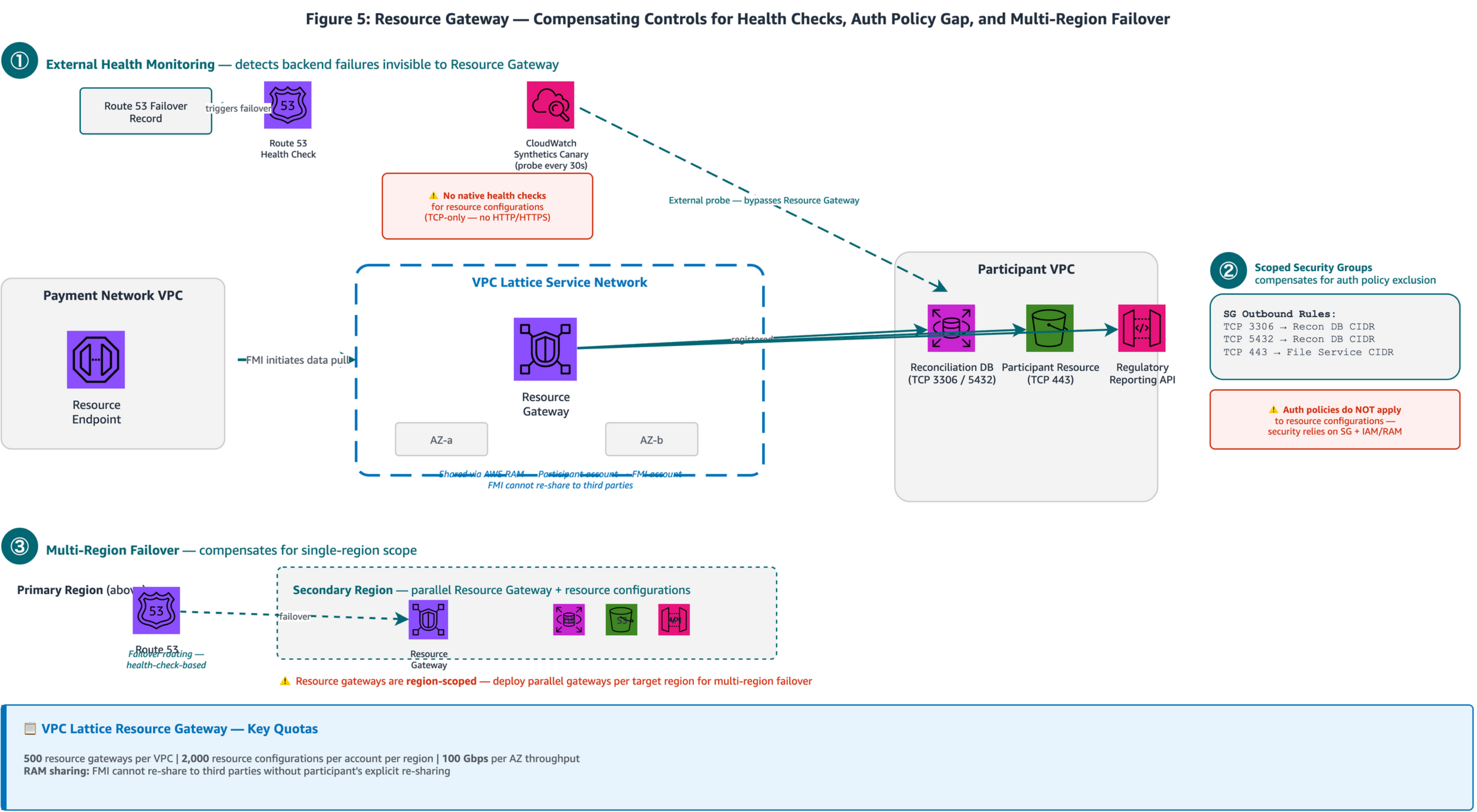
Figure 5: FMI VPC (left) containing Resource Endpoints connecting through a VPC Lattice Service Network to the participant’s Resource Gateway (center). Three production best practice callouts: (1) CloudWatch Synthetics Canary probing data endpoints with Route 53 failover routing; (2) Resource Gateway security group outbound rules scoped to specific ports; (3) Multi-Region failover with parallel Resource Gateway deployment.
- Unlike AWS PrivateLink where the consumer initiates connectivity to the service provider, Resource Gateway allows the FMI (as consumer) to reach specific resources in the participant’s VPC without the participant operating an NLB or endpoint service. Pattern 4 from the FMI connectivity blog uses this model: the customer deploys a Resource Gateway, registers specific resources by IP address, Domain Name System (DNS) name, or ARN, and shares the gateway with the FMI’s account through AWS Resource Access Manager (AWS RAM). The FMI then creates Resource Endpoints in its VPC to reach the registered resources. Resource Gateway is a component of VPC Lattice. It appears in both AWS PrivateLink documentation and VPC Lattice documentation because it bridges the two services, but it is inherently part of the VPC Lattice architecture. Resource Gateway supports up to 100 gateways per VPC, 2,000 resource configurations per account per Region, and 100 Gbps bandwidth per AZ, generous for most payment reconciliation workloads but worth monitoring proactively ahead of high-volume settlement periods.
- VPC Lattice health checks apply to target groups (services) with configurable HTTP/HTTPS checks: interval 5–300 seconds, timeout 1–120 seconds, healthy threshold 2–10, unhealthy threshold 2–10. Resource configurations use TCP-only protocol, so adding external health monitoring provides application-level visibility. Deploy Route 53 health checks or Amazon CloudWatch Synthetics canaries that probe the actual data endpoints directly, triggering DNS failover independently of the Resource Gateway.
- VPC Lattice provides defense-in-depth with three security layers: explicit VPC/endpoint association, security groups and network ACLs, and optional auth policies. For resource configurations, security groups and IAM/RAM controls are the primary enforcement points. Resource Gateway security groups control outbound traffic from the gateway to the registered resources (gateway-to-resource direction). This is distinct from typical inbound security group rules. Lock these outbound rules to specific database or file-service ports (for example, TCP 3306, 5432, or 443) and restrict the destination CIDR to the registered resource’s IP range, ensuring precise access control within the participant VPC.
- Resource gateways are Region-scoped: bound to a VPC and its subnets within a single Region. For multi-Region payment deployments requiring failover of reconciliation and settlement data pulls, deploy parallel resource gateways and resource configurations in each target Region and use Route 53 failover routing to direct FMI clients to the active Region. AWS RAM sharing governance supports the participant sharing the resource configuration with the FMI’s account. Within an AWS Organization, consumers receive automatic access; outside the Organization, they must accept an invitation. The FMI cannot re-share access to third parties without the participant’s explicit re-sharing.
Important: Auth policies on the VPC Lattice service network apply to services but not to resource configurations. Security groups (outbound rules) and IAM/RAM controls are the primary enforcement points for resource configurations. Scope your outbound security group (SG) rules to specific ports and destination CIDRs.
Apply this pattern when FMIs need to pull reconciliation data, settlement files, or regulatory reports from participant environments, particularly when avoiding the operational overhead of deploying and managing NLBs and endpoint services. The tradeoff is additional operational overhead for external monitoring infrastructure and SG rule management, but this provides the application-level visibility and access control precision that production payment workloads require.
Security Considerations
Encryption in transit operates at two layers across these patterns. For organizations operating AWS Direct Connect as part of a migration path or hybrid architecture, MACsec (IEEE 802.1AE) provides Layer 2 point-to-point encryption on dedicated connections at 10 Gbps, 100 Gbps, and 400 Gbps at select locations. TLS secures traffic across the AWS PrivateLink boundary, with NLB supporting TCP passthrough to preserve end-to-end TLS or TLS termination at the load balancer. For payment flows traversing Direct Connect, the complete encryption chain is:
on-premises payment router → (MACsec) → Direct Connect edge → (AWS physical-layer encryption) → VPC endpoint ENI → (TLS) → NLB → payment backend targets.
For deployments without Direct Connect, TLS across the AWS PrivateLink boundary provides the encryption layer, with AWS physical-layer encryption protecting data in transit between AWS facilities.
For DNS resolution and failover, enabling private DNS on an interface endpoint creates an AWS-managed Route 53 private hosted zone that overrides the service’s public DNS name to resolve to endpoint ENI private IPs within the VPC. Zonal DNS names (for example, vpce-xxx.us-east-1a.vpce-svc-xxx…) support AZ-aware routing. Route 53 health checks with 10-second intervals and a two-of-three failure threshold provide sub-minute failover detection aligned to payment SLA requirements. Payment workloads should prefer zonal DNS resolution to avoid routing transactions to an impaired AZ.
AWS PrivateLink publishes Amazon CloudWatch metrics at 1-minute intervals including ActiveConnections, BytesProcessed, NewConnections, PacketsDropped, and RstPacketsReceived. The last metric is particularly valuable for monitoring connection lifecycle behavior described in Pattern A. NLB access logs can be delivered to Amazon CloudWatch Logs, Amazon S3, or Amazon Data Firehose for real-time analysis of connection patterns and TLS handshake details. VPC Flow Logs v3 fields capture PrivateLink ENI traffic including pkt-srcaddr, pkt-dstaddr, and tcp-flags for connection-level analysis.
Table 3: Observability — Key Metrics and Alert Thresholds per Pattern
| Pattern | Key Metric | Source | Alert Threshold | Rationale |
|---|---|---|---|---|
| A – Connection Persistence | RstPacketsReceived |
AWS PrivateLink CloudWatch | > 0 sustained over five minutes | Indicates NLB idle timeout expiring connections; keepalive probes not reaching NLB |
| B – Graceful Maintenance | HealthyHostCount (per target group) |
NLB CloudWatch | < expected count for > three minutes | Indicates targets draining or failing health checks during maintenance |
| B – Graceful Maintenance | ActiveFlowCount (blue TG) |
NLB CloudWatch | > 0 after deregistration delay expires | Indicates connections not draining as expected |
| C – Tenant Isolation | ActiveFlowCount / NewFlowCount (per NLB) |
NLB CloudWatch | Tenant-specific baseline ± two std dev | Per-tenant capacity monitoring; independent metrics per dedicated NLB |
| D – Resource Gateway | SuccessPercent |
CloudWatch Synthetics | < 100% for two consecutive checks | Canary detecting data endpoint unavailability before FMI pull fails |
| D – Resource Gateway | Route 53 Health Check Status | Route 53 | Unhealthy (two-of-three failures) | Triggers DNS failover to secondary Region |
Conclusion
In this post, we presented four patterns that move AWS PrivateLink and Resource Gateway connectivity from reference architecture to production-grade payment infrastructure:
- Pattern A (Connection persistence): universal baseline for any persistent-session protocol traversing NLB-backed AWS PrivateLink. Requires no architecture changes, only sysctl configuration.
- Pattern B (Graceful maintenance): zero-downtime deployments for stateful payment backends where session continuity is required.
- Pattern C (Tenant isolation): connection-level isolation with independent capacity per tenant for multi-tenant platforms.
- Pattern D (Resource Gateway hardening): production-grade health monitoring and access control precision for FMI-initiated data pulls.
Each pattern is independently adoptable. Start with Pattern A as an immediate operational improvement, then layer Patterns B through D based on your operational maturity, tenant model, and specific requirements. Validate each through controlled experiments: observe connection behavior across idle windows (A), exercise the weight-shift sequence in a staging environment (B), confirm tenant isolation under load (C), and test multi-Region failover (D).
Together, these patterns give architects and network engineers the operational playbook to run production payment connectivity on AWS from day one.
If you have questions or want to share your experience implementing these patterns, leave a comment below. For more information, see the following resources: