AWS Database Blog
How SGK simplified the data structure of a highly dynamic workload by migrating from an RDBMS to Amazon DynamoDB
Many database solutions are available today, and choosing the right one for your use case can be difficult. Recently, NoSQL databases have been widely adopted for real-time web applications. Amazon DynamoDB is an example of a NoSQL database that is optimized to yield significant flexibility and performance benefits over a traditional relational database management system (RDBMS). A traditional RDBMS can be limited by its table design, which is fixed and schema-based.
In this blog post, SGK Solutions Architect Murugan Poornachandran explains how SGK created an optimal design pattern for SGK’s dynamic client configurations and rules. This design uses DynamoDB to accommodate SGK’s evolving microservices architecture and diverse stakeholders. This new design was a significant improvement over SGK’s legacy RDBMS solution. Murugan also explains how SGK has used the schemaless table feature in DynamoDB with a normalized relational data model to manage or automate the frequent changes in their data management system. This approach substantially reduces the time required for data processing.
Background information
SGK’s Global Content Creation Studio network creates content and solutions that connect brands and products to consumers through photography, video, and copywriting. When transitioning from large enterprise, multitenant applications to a microservices architecture, one key challenge we at SGK encountered was managing clients and their variable configurations and rules.
For example, we needed to share our client and configuration data across all our microservices. Client data includes categories, departments, and locations, and configuration parameters include security-related details such as access permissions and roles. In addition, clients’ configurations and rules needed to be continually customized for different users and shared across multiple microservices.
As we released new microservices on a regular basis, it became even more challenging for us to maintain the ever-changing client and configuration data in our relational database. The key challenge was that each new microservice required database modifications and also time-consuming updates to an object relational mapping at the application layer. As the complexity of our data management system increased with each new microservice, we decided to create a new REST-based managed service, the Dynamic Reference Data Service (DRDS). DRDS uses DynamoDB as its primary data store to manage the dynamic client configurations and rules. DRDS is completely serverless and uses Amazon API Gateway and AWS Lambda to serve the API, and its user interface is hosted on Amazon S3.
We found that you can reduce the complexity of a relational data model using a NoSQL solution implemented with DynamoDB. In addition, we discovered that you can also use this solution to simplify the operation of a highly dynamic workload.
Solution overview
SGK’s experience with DynamoDB dates back to 2014. Understanding the tradeoffs of relational versus NoSQL designs was an important step in redesigning our data tier. We realized that a NoSQL solution would allow us to optimize performance while reducing operational overhead. Ultimately, though, a well-designed data model makes all the difference in how an application performs.
When data modeling, we found it useful to begin with entity relationship modeling to define the entities, attributes, and relationships in your application. Entities are the primary objects in your application, attributes are the object properties, and relationships are the connections between entities. There are three kinds of relationships: one-to-one, one-to-many, and many-to-many. These are often represented as 1:1, 1:N and M:N, respectively, and we use these notations in this post to represent relationships.
Typically, in a relational design, the focus is on describing the entity and its relationships. The queries and indexes are designed later. However, a NoSQL design uses a query-first approach. In this approach, you identify queries first, and then you design the primary key and optional indexes to provide fast and efficient access to data.
Our solution uses a single DynamoDB table that eliminates the complexity of modeling M:N relationships and a global secondary index to manage many-to-many relations. We defined our query patterns up front and specified an appropriate primary key. This NoSQL approach was useful and helped simplify our DynamoDB data model as we migrated from an RDBMS.
Let’s review SGK’s DynamoDB data model in more detail to understand these concepts.
SGK’s DynamoDB data model
The following is SGK’s DynamoDB table definition. We created a global secondary index on the table’s sort key (id) to manage M:N relationships. We discuss incorporating the global secondary index into the design in the M:N relationship example in the following section.
| Field | Type |
| type (primary partition key) | String |
| id (primary sort key) | String |
| name | String |
| Any data attributes (as needed) | String|Date|Numbers|Boolean| |
The preceding DynamoDB table design is the key to SGK’s flexible solution. We made the following data design decisions and conventions to support the JSON document relationships:
- Field
type– The partition key defines the kind of entity. You can consider thetypename as thetablename in a relational database. For example, you can view all rows withtypethat start withCountryas representing a country table in a relational database. - Field
id– The sort key is designed as the primary key fortyperecords so that the sort key is used as a mechanism to retrieve related records. For example, if we have 10 countries and want to store the states for each country, thetypestarts withCountryand the id value isStateconcatenated with the country code and state ID (for example,State-US-CA,State-US-NY, andState-CA-ON). The substringUSorCAis the ID value forCountryrecords and creates an implicit 1:N relationship between countries and states. This approach makes it easy to retrieve all US states using abeginsWithUS filter on the sort key. Similarly, to query all cities from California, use abeginsWith US-CAfilter on the ID field for thetypeofCity.You can see an example of this data model in the following image:

In the preceding example, we can store and query all related details for a country by using the partition (type) and sort (id) keys. This approach makes it easy to query, for example, US country information and related state and city details together by simply querying with partition keytype = 'Country-US'. We also can easily filter the states alone by adding the sort key condition IDbeginsWith 'State', if needed. Similarly, we can create a ‘State-IL‘ partition as needed to manage state-related details. - Metadata is defined when the
typefield isconfigurationand captures the number of unique tables. These configuration records define the fields and relationships for each table. We discuss configuration data in more detail in the following section.
With this data design, we can create a dynamic, flexible data model with relationships.
Configuration data
In SGK’s solution, configuration data describes the entity and fields (in other words, the client data) stored in the master-data entity. This configuration metadata doesn’t define or manage any relationships in DynamoDB, but it is critical to understanding how many entities exist and how they are related. The following screenshot shows how we configure Country for an application ‘xyzonlinestore‘.
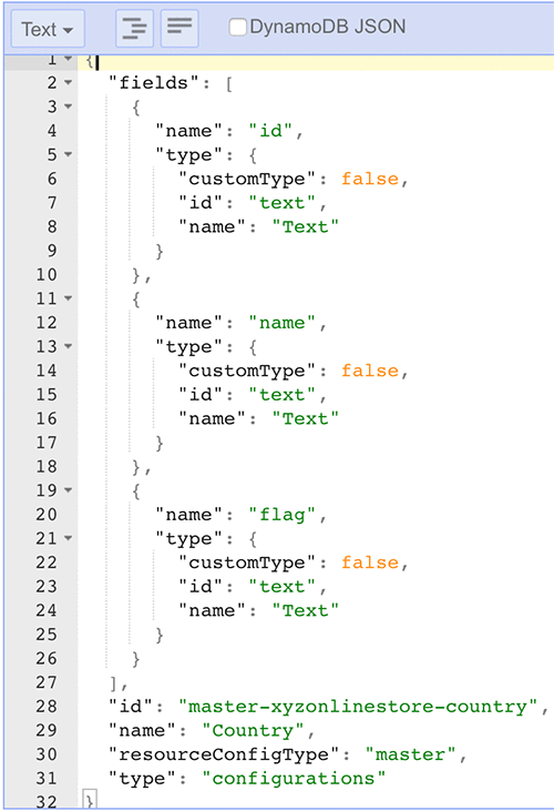
Let’s review the JSON shown in the preceding screenshot in more detail:
- The sort key is specified as the id field on line 28 as
master-xyzonlinestore-country.- The prefix
masterin the sort key refers to the specific type of client data;xyzonlinestoreis the microservice (or application) under configuration;countryis the configured entity.
- The prefix
- The
namefield on line 29 indicates that we are configuringCountryas client data. - The partition key is the
typefield on line 31 and is set toconfigurations.
With this approach, we can associate a client resource with any number of attributes within a JSON object. In this example, we defined three attributes in the fields record starting on line 2: id, name, and flag.
If we need to add more attributes at a later time, changing the Country entity structure is easy in DynamoDB. We can simply update the JSON object with new fields. In contrast, in an RDBMS, we would need to update multiple tables, relationships, and indexes, including the data access object (DAO) at the application layer.
This strategy gives us flexibility to add and remove client resource definitions quickly and dynamically.
Now, let’s walk through a 1:N relationship example.
1:N relationship example
In RDBMS, a 1:N relationship occurs when a parent record in one table can potentially reference several child records in another table. In a 1:N relationship, the child record cannot have more than one parent record. This logic is useful for tracking relevant child records associated with an entity. To continue our example in this post, consider a scenario where we want to configure a list of cities for a State resource. For example, the State resource for Illinois contains multiple cities. We can issue a query to list all cities in Illinois by using a filter where type=State-IL and id beginsWith City.
Now, let’s look at an example of a M:N relationship.
M:N relationship example
In RDBMS, a M:N relationship occurs when multiple records in a table are associated with multiple records in another table. An RDBMS usually does not allow you to implement a direct M:N relationship between two tables. Typically, you break the M:N relationship into two 1:N relationships using a third table. With DynamoDB, we were able to implement a M:N relationship within a single table and a global secondary index.
Let’s say we have a list of products associated with several countries. By implementing the adjacency list design pattern that uses a global secondary index, we can easily represent this M:N relationship in DynamoDB with minimal duplication of data.
The following image shows an example of how this M:N relationship works. The master-data table shows the 1:N relationship of products to countries. The global secondary index for master-data shows the 1:M relationship of countries to products. Together, these form the M:N relationship of these two entities.
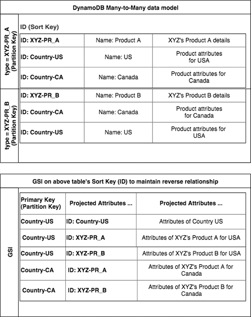
In this example, product data of XYZ is stored on its own partition. This partition contains the product information and also a list of associated or supported countries. The first sample in the preceding table shows Product A’s details for the US and Canada. To list all countries supported by Product A, we can issue a query against our DynamoDB table where type='XYZ-PR_A' and ID beginsWith 'Country-'.
The global secondary index helps us view this relationship from the perspective of a country. For example, to list all products for Canada, issue a query against the global secondary index where IndexName = 'Country-CA'. This approach is more efficient than trying to query the data directly from the master-data</code table.
So far, in this blog post, we have seen how efficient it is to use DynamoDB to manage a single table of our data containing 1:N and M:N relationships. We can successfully manage our client entities and their relationships that often change using these effective partition and sort key data models and DynamoDB flexible design.
Now, let’s compare this design to our legacy RDBMS solution.
SGK’s previous RDBMS reference data model
In contrast to the DynamoDB solution we’ve described, our RDBMS solution worked quite differently. In our RDBMS solution, each client entity was a separate table with its own attributes, indexes, and foreign key relationships. We had to maintain each of these relationships individually. The RDBMS’s data model appears in the following diagram.

As the preceding diagram shows, the country table has a M:N relationship with the products table. This relationship is modeled as a 1:N relationship using the products_country_association table. The state table has a 1:N relationship with the city table, and the country table has a 1:N relationship with the state table.
The RDBMS design worked for us when we didn’t have to make frequent updates to the schema. The challenge was that we did have to make frequent changes because of our evolving microservice architecture, such as adding tables, fields, and relationships. Using the relational data model forced us to spend many development cycles managing our client data.
With our DynamoDB data model, both tables and fields are configurable, and we no longer have to use additional development cycles to keep up with our microservices architecture. We can easily manage these complex relationships in DynamoDB through dynamic configurations.
Summary
SGK’s dynamic DynamoDB data model allowed us to create a fully managed service to store and serve a variety of client data to fulfill both current and future needs. This solution has led to significant reductions in operational maintenance and allows us to focus on our clients’ business needs.
About the Authors
 Murugan Poornachandran is a seasoned enterprise and cloud solutions architect. He has expertise in JEE and AWS solutions. He is currently designing AI solutions using AWS and moving large enterprise applications into AWS Cloud using micro-service architecture and AWS server-less solutions at SGK Inc.
 Wangechi Doble is a Principal Solutions Architect with a focus on Big Data & Analytics at AWS. She helps customers architect and build out high performance, scalable and secure cloud-based solutions in AWS.