AWS for Industries
Auto-healing Persistent Virtual Network Functions on AWS
Introduction
Network Functions Virtualisation (NFV) is an architecture concept in the telecom industry to enforce state-of-the-art technologies onto servers, network devices, and storage, in order to virtualize Network Functions (NFs).
These days, multiple service providers are conceiving their virtual NFs (VNFs) in AWS, and this trend is accelerating further with containerized NFs (CNFs) and 5G.
AWS addresses some of these NFV needs with features like increased bandwidth throughput up to 100 Gbps in Amazon Elastic Compute Cloud (EC2) instances (both with Intel processors and Graviton processors), Enhanced Network Adapter (ENA) module and drivers, the AWS Outposts service, and up to 100Gbps support on the AWS Direct Connect service. AWS provides best practices aligned with them and our Well-Architected Framework, such as high-availability designs for AWS Outposts or 5G network design guidelines.
Many telecom use cases are based on standalone Virtual Network Functions (VNFs) with multiple connections to remote clients or peers, such as virtual session border controllers (SBCs), virtual L2TP Network Servers (LNSs), or virtual IPsec or GRE tunnel concentrators, which use IPv4 addresses as connection or session endpoints, rather than DNS names. These remote clients or peers need that these connections remain persistently configured with the same destination IPv4 addresses across failover, restoration and lifecycle management activities. Changing IPv4 addressing for the VNF would require updating an installed base of remote devices, leading to additional maintenance works, costs and risks.
This blog post explains a solution available under https://github.com/aws-samples/auto-healing-persistent-virtual-network-functions/, which covers two challenging aspects for these VNF deployments: auto-healing (or self-healing) and IPv4 address allocation persistence in AWS. This architecture is also applicable to other environments, but I exemplify it here for an NFV use case, including the option to select as standalone VNF any custom EC2 image or a preselected virtual appliance, such as a Cisco Systems CSR1000v router, a Juniper Networks virtual SRX (vSRX), or a Juniper Networks virtual MX (vMX) router.
Solution Overview
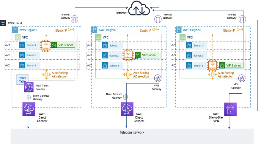 Figure 1: Sample VNF deployments across different AWS Availability Zones
Figure 1 depicts three deployment options for a telco using this architecture, each in a given Availability Zone (AZ). This VNF is represented by an Amazon EC2 instance and its network topology includes a primary interface connected to an Amazon Virtual Private Cloud (Amazon VPC) private subnet and a secondary interface connected to a unique VPC public subnet, called VIP subnet in this solution. A private IPv4 address for the VNF secondary interface in this VIP subnet is pre-allocated and a public Elastic IP address (EIP) is mapped to it. The VNF can be reached under known private and public IPv4 addresses associated to its secondary interface.
This solution is an event-driven architecture that manages lifecycle workflows for the VNF. Every time the VNF is launched, this VIP subnet is created and attached to the VNF, and a secondary interface is created and attached to this VIP subnet with the same pre-allocated private IPv4 address and public EIPs. Whenever the VNF is terminated, the secondary interface and the VIP subnet are detached and deleted.
These workflows enforce a ubiquitous VNF deployment model in any AZ from any AWS Region, which may be connected to the internet and a local telco network, because the VNF is always reachable publicly and also privately through AWS Direct Connect or Site-to-Site VPN services under the same pair of private and public IPv4 addresses.
Prerequisites
This solution is deployed through AWS Serverless Application Model (AWS SAM). AWS SAM is an open-source framework that enables you to build serverless applications on AWS and create resources through a main AWS CloudFormation template in YAML.
Before the AWS SAM deployment, a set of prerequisites must be fulfilled.
AWS account credentials and permissions
Obtain access to an AWS account and AWS Identity and Access Management (IAM) user credentials that provide the necessary permissions. Deploying this solution requires IAM permissions equivalent to the following managed IAM policies:
AmazonEC2FullAccess,IAMFullAccess,AutoScalingFullAccess,AmazonS3FullAccess,AmazonVPCFullAccess,AmazonSSMReadOnlyAccess,AmazonSNSFullAccess,CloudWatchEventsFullAccess,AWSCloudFormationFullAccessAWSLambda_FullAccess.
You can create your specific IAM user with these IAM managed policies or the equivalent permissions. You can set the corresponding environment variables for this IAM user in the CLI, which includes AWS Access Key ID and AWS Secret Access Key.
AWS Serverless Application Model (SAM) CLI installation
Install the AWS SAM CLI in your client computer. This installation is available for Linux, Windows and macOS, and includes the enforcement of the AWS account environment installation, an optional Docker installation and the SAM CLI package installation itself. You can visit The AWS Serverless Application Model CLI is now generally available blog post for further details.
Resource planning
Create an Amazon EC2 KeyPair within the AWS account, that may be used for secure instance access via SSH.
Decide if direct SSH access to the VNF is required, and if enabled, identify the IPv4 CIDR range that may cover the source IPv4 address segment that may be used for direct SSH access.
Select the VNF type to use, which will be defined by its Amazon Machine Image (AMI). This sample code distinguishes between two main options for AMI selection:
- Your own AMI, which is determined by the input
InstanceChoiceparameter left withCustomvalue and the specific AMI ID entered at theCustomAIMIdparameter as the AWS Systems Manager Parameter Store path to that AMI ID (defaults to Amazon Linux 2 AMI). The Parameter Store is a capability from the AWS Systems Manager service that provides secure, hierarchical storage for configuration data management and secrets management, centrally storing data such as AMI IDs as parameter values that can be retrieved by other AWS Services and decoupling these values from the code. You can find a good usage example at this blog post. - A preselected AMI from Cisco Systems CSR1000v, Juniper Networks virtual SRX (vSRX)or Juniper Networks virtual MX (vMX) virtual appliances as the VNFs. In those cases, you will select these specific values for the
InstanceChoiceparameter and theCustomAIMIdparameter value will be ignored, as the AMI IDs have been preloaded.
These virtual appliances are preselected from the AWS Marketplace. The AWS Marketplace is an online store where Independent Software Vendors (ISVs) and consulting partners can sell their solutions that run on AWS. This provides a sales channels for AWS users to find, buy and immediately start using software or services from 3rd parties, but implemented on AWS.
Before using any of these preselected virtual appliances, you need to request its subscription in the AWS Marketplace. The subscription process for these third party virtual appliances in the AWS Marketplace is explained in detail in the solution GitHub repo section and at the AWS Marketplace Getting started as buyer section.
Deployment
This solution is available under https://github.com/aws-samples/auto-healing-persistent-virtual-network-functions/, which is locally cloned as part of the first SAM initialization stage (see Step 1 below). It uses AWS SAM to orchestrate the stack deployment, based on nfv_infrastructure_and_vnf.yml as the main AWS CloudFormation template. The code package also includes python files under the src/ directory for the AWS Lambda functions, sample deployment configurations under sample_configs/ and other diagrams under diagrams/. This template creates all AWS resources and you will be billed for them in the specific AWS account.
If you decide to choose any of the preselected virtual appliances, I have preloaded bring-your-own-license (BYOL) versions for these vendors from the AWS Marketplace for test purposes, so you are expected to also bring in your corresponding license and AWS will charge you just for the EC2 compute costs. If you want to install these licenses, you can visit the corresponding sections from the Cisco CSR 1000v software configuration guide, the Juniper vSRX licensing guide or the Juniper vMX licensing guide.
Once all previous prerequisites have been fulfilled, you are ready to deploy the solution following these steps:
- Run
sam initthen chooseCustom Template Locationand pastehttps://github.com/aws-samples/auto-healing-persistent-virtual-network-functions/, which will clone this repository locally in your client computer. - Build the AWS SAM application by running in your CLI
sam build -tnfv_infrastructure_and_vnf.yml - Deploy the AWS SAM application. Initially, you can opt for a guided deployment with
sam deploy –guided. Several parameters are required for the stack instantiation and I recomend to start with default hinted values for each parameter and then iterate and fine tune, depending on your use case:AvailabilityZones: 3 Availability Zones where the VNF can be instantiated as decided by the Amazon EC2 Auto Scaling group. You can repeat an AZ if you want to increase preference weight for a given AZ selection.KeyPair: An Amazon EC2 Keypair to directly access the device per SSH, as per prerequisites. This keypair applies to each instance type, and is associated toec2-userusername per default in Amazon Linux 2, Cisco CSR1000v and Juniper vSRX, and tojnpruser in Juniper vMX.PublicSSHAccess: Configuration option (trueorfalse) to decide if external SSH access from public IPv4 addresses is allowed or not. If allowed, the source range is determined underJumpHostIPrange. If not allowed, only AWS Systems Manager Session Manager access will be available.JumpHostIPrange: Source public IPv4 Address range allowed to connect to the instance management port per SSH. Only applicable ifPublicSSHAccessis true.SnsEmail: The email address that receives SNS notifications about VNF topology changes.LambdaInfoTracing: Configuration option (trueorfalse) to include log INFO level details in AWS Lambda CloudWatch logs or notASGCoolDownTime: Time (in seconds) to guard between consecutive launch and terminate actions in the EC2 Auto Scaling Group. This depends on the bootup time of each instance, so it is recommended to start with the default hinted value (10) as the bare minimum. The default value in AWS for the EC2 Auto Scaling CoolDown time is 300 seconds.ASGHealthCheckGracePeriod: Grace time (in seconds) to wait before checking the instance health status after launching the EC2 Auto Scaling Group. This depends on the bootup time of each instance, so I recommend to start with the following recommended tested values as the bare minimum, but also to be conservative, as this value may change over time and depend on your specific VNF version (the generic default value in AWS is 300 seconds).- For
Amazon Linux 2:10 - For
CiscoCSR1000v VNF:10 - For
JunipervSRX VNF:600 - For
JunipervMX VNF:1020
- For
ASGUpdateHealthCheckGraceTime: Grace time (in seconds) after creation of EC2 Auto Scaling Group Lifecycle hooks and before launching first instance. It is recommended to start with the default hinted value (120) as a minimum and you can adjust it afterwards.SubnetCreationAttempts: Number of attempts to create the VIP subnet within same Lifecycle Launch stage. This also depends on the bootup time of each instance, I recommend to start with the default hinted value (10) as a minimum.VPCCIDRBlock: The overall Classless Inter-Domain Routing (CIDR) IPv4 address block for the VPCWANSubnetCIDRBlocks: specific CIDR address blocks for primary interface subnets in each AZ, they need to be included within the overall VPC CIDR address blockVIPCIDRBlock: The specific CIDR Block for the VIP subnet.VIPAddress: within theVIPCIDRBlockaddress range, this identifies the specific private IPv4 address (/32) that is persistently allocated to the VNF secondary interface and mapped to the public EIP.InstanceChoice: you can choose between preselected AMIs withCiscoCSR1000v,JunipervSRXorJunipervMXvalues, or choose a Custom image that can be specified as aCustomAIMIdwithin AWS Systems Manager Parameter Store (which defaults toAmazon Linux 2). Note that this is a string parameter value and you need to keep this specific syntax when entering this in a SAM deployment.InstanceType: EC2 instance type for the VNF. In this code sample, you can entert3.micro(overall default),c5.large,c5.2xlargeorm5.large. Each vendor provides recommended default values at the AWS Marketplace: forCiscoCSR1000vBYOL andJunipervSRXBYOL it isc5.large, and forJunipervMXBYOL it isc5.4xlarge. Note that this is a string parameter value and you need to keep this specific syntax when entering this in a SAM deployment.InstanceRequiresReboot: Configuration option (trueorfalse) that enforces a VNF reboot after attaching the VIP subnet secondary interface. This depends on the specific VNF behavior, and if it supports dynamically attaching an ENI without requiring restart or not.JunipervSRXandJunipervMXhave been tested requiring a restart after dynamic interface attachment (true), others likeCiscoCSR1000vor a plainAmazon Linux 2instance can dynamically incorporate additional ENIs without requiring a reboot (false)CustomUserData: Optional free text field to enter User Data whenever a custom instance is selected (only needed if the VNF is neitherCiscoCSR1000v, norJunipervSRX, norJunipervMX, because basic User Data is already provided for those cases).
Figure 2 shows you a sample SAM guided deployment with an Amazon Linux 2 EC2 instance. Amazon Linux 2 is chosen by default, because the InstanceChoice parameter remains Custom and the CustomAmiId field has not been modified to point to any specific AWS Systems Manager Parameter Store path. You can also see how specific bootstrap User Data is base64-encoded and entered within the CustomUserData field. For further details about this, please check https://docs.aws.amazon.com/AWSEC2/latest/UserGuide/instancedata-add-user-data.html. The parameter CustomUserData is ignored if you choose a preselected virtual appliance, because this sample code comes with specific User Data in those cases.
 Figure 2: Sample SAM guided Amazon Linux 2 deployment
You can check additional sample deployment examples with other values and virtual appliances under Sample Deployment Choices. The AWS SAM guided deployment final questions will ask you to confirm the stack creation with those parameters, as you can see in Figure 2, and it gives you the option to save these entered parameters in that local .toml file.
The AWS SAM CLI supports a project-level configuration file that stores default parameters for its commands in that TOML file format. By using this .toml configuration file, you can opt for a direct stack launch in further deployments later, just by entering sam deploy –config-file<sample.toml>, where <sample.toml> is the parameter configuration file, rather than going through the guided deployment menu again. You have several sample TOML configuration files under https://github.com/aws-samples/auto-healing-persistent-virtual-network-functions/tree/main/sample_configs and concrete instructions at Advanced Configuration Deployment.
The deployment execution takes approximately 10 minutes to complete. Because an SNS topic is created, an e-mail will be sent to the SnsEmail Parameter value to confirm the SNS subscription and to notify subsequent events. You would need to accept an initial e-mail upon stack creation to be able to receive further topology notifications.
During the stack creation time, the VNF instance creation is delayed for the amount of time specified under ASGHealthCheckGracePeriod, so this will affect your overall initial solution standup time.
Once you have deployed that stack first, it is no longer needed to build the AWS SAM application again, unless you have changed the package code. If you need to re-deploy, you can opt for a more programmatic Advanced Configuration Deployment with your TOML configuration file.
Walkthrough
Let us explore now the deployed solution building blocks:
Auto-healing (or self-healing)
Amazon EC2 Auto Scaling provides instance groups with options to set minimum, maximum and desired capacity values, and other features for restoration, auto-healing, scale-out and scale-in, such as:
- Manual Scaling
- Dynamic Scaling
- Scaling cooldowns
- Lifecycle hooks
- Custom health checks
- Warm pools
- Temporary removals or suspension
An Amazon EC2 Auto Scaling group deployment is built on top of declarative definitions, like a fixed number of instances as minimum, desired, and maximum capacity. I am using this capacity definition to set a persistent desired and maximum capacity of 1. The EC2 Auto Scaling group starts by launching that instance according to its defined deployment options in one of its associated AZs.
Amazon EC2 Auto Scaling monitors the health of each launched Amazon EC2 instance. Whenever an instance is unhealthy, terminates, or gets stopped, Amazon EC2 Auto Scaling launches a new one, according to the Auto Scaling group configuration and a backoff mechanism that selects a different AZ over time, as you can see in Figure 3.
 Figure 3: Sample VNF network configurations across different AWS Availability Zones
Amazon EC2 Auto Scaling is independent from the EC2 instance itself and provides the required self-healing behavior to always relaunch a given EC2 instance upon termination.
IPv4 Address Allocation Persistence
An EIP provides a static public IPv4 address in an AWS Region. It can be allocated and dynamically associated to an instance interface. This implements one-to-one Network Address Translation (NAT) for private IPv4 addresses, but it is then only publicly reachable.
Some hybrid cloud environments in telcos extend their backbone networks to AWS Regions, as shown in Figure 1. In those cases, private RFC1918 IPv4 addresses are used across this joint infrastructure, but they are not reachable from the public internet. Ideally, a globally unique private IPv4 address fulfills this requirement.
AWS provides a PrivateIpAddress parameter within the set of API calls that create or modify elastic network interfaces (ENIs). This parameter allows the preassignment of determined IPv4 addresses for the DHCP lease in AWS. However, Amazon EC2 Auto Scaling groups do not support such preassignment in their definition.
Combining Auto Scaling Groups and Persistent IPv4 Assignments
With additional AWS services, it is possible to address these needs with the following architecture as per Figure 4:
- A launch template for the VNF EC2 instance with a primary interface in a VPC private subnet, bootstrap configuration as UserData, and other settings
- A persistent EC2 Auto Scaling group that uses that launch template enabled across AZs
- Auto Scaling lifecycle hooks that capture instance termination and launch stages
- An AWS Lambda function that manages the lifecycle of a secondary ENI, including subnet creation, interface creation with a preassigned private IPv4 address, attachment and allocation for the launch events, and the reverse sequence for the termination events
- An Amazon CloudWatch or Amazon EventBridge event that uses lifecycle hooks as triggers and this Lambda function as the destination to manage this ENI lifecycle
- Another pair of CloudWatch or EventBridge event and AWS Lambda functions to address the initial warmup period for the EC2 Auto Scaling group, and AWS CloudFormation custom resources for the solution deletion.
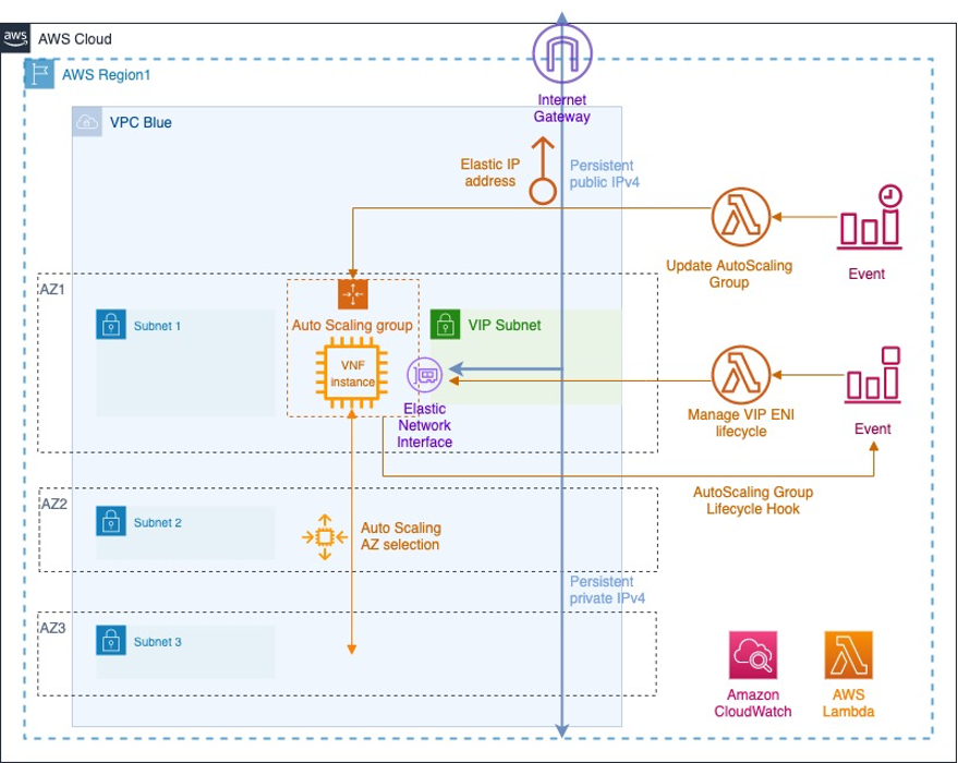 Figure 4: Amazon EC2 Auto Scaling group, Amazon EventBridge events and AWS Lambda functions for VNF network configuration
Launch Templates and Auto Scaling Groups for VNFs
Launch templates abstract some of the common EC2 instance configuration aspects in a reusable fashion. I have defined some basic properties in each launch template, such as AWS EC2 instance type, VNF AMI, IAM instance profile, and a primary network interface.
The UserData configuration is included as a LaunchTemplate property and is specific to each VNF (custom as per the CustomUserData input parameter, or a default basic configuration for Cisco Systems CSR1000v, Juniper Networks vSRX, and Juniper Networks vMX). There is a LaunchTemplate resource for each VNF type because its UserData and AMI resources are different in each case.
The Auto Scaling group resource selects the respective launch template for each VNF and defines additional mechanisms, like health-check grace period (between instance launch and health check starts, see ASGHealthCheckGracePeriod input parameter), cooldown period (to prevent the initiation of an additional scaling activity based on stale metrics, see ASGCoolDownTime input parameter), subnets to deploy the instance (up to 3 AZs), and the rolling update policy (no more than 1 instance in place). It also includes main dimensioning properties to set maximum, minimum, and a DesiredCapacity.
An auxiliary AWS Lambda function is included in the SAM application to update the EC2 Auto Scaling group configuration with a DesiredCapacity of 1 after the ASGUpdateHealthCheckGraceTime time period. This implements the initial warmup by capturing the very first instance launch event with the Auto Scaling group creation.
EC2 Auto Scaling Group Lifecycle Hooks
EC2 Auto Scaling groups allow triggering workflows during launch and termination stages through lifecycle hooks. In this solution, the EC2_INSTANCE_LAUNCHING and EC2_INSTANCE_TERMINATING hooks trigger events to manage the lifecycle of this secondary ENI and its public and private IPv4 addresses, as you can see in Figure 5:
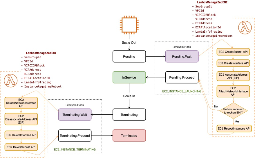 Figure 5: Amazon EC2 Auto Scaling group state machine with actions for lifeceycle hooks
These lifecycle hooks are captured as launch or termination event triggers that invoke the same AWS Lambda function with context information for the secondary ENI lifecycle management.
Just by distinguishing the type of event (launch or termination), I enforce a sequence of actions for each stage inside the AWS Lambda function. This implementation decouples the EC2 Auto Scaling group from the secondary ENI itself.
Secondary ENI, Elastic IPv4 Address and Private IPv4 Address Lifecycle Management
Through this AWS Lambda function, the EC2 Auto Scaling group state machine can be expanded as explained in Figure 6:
 Figure 6: Sequence of API calls carried out by auxiliary AWS Lambda function during Launching and Terminating lifecycle hooks
Upon EC2_INSTANCE_LAUNCHING, the following actions are carried out by the AWS Lambda function in order:
- Create a new subnet in the same AZ with the VIP CIDR block range.
- Create an ENI in that subnet with the PrivateIpAddress.
- Associate that private IPv4 address to the public EIP address.
- Attach this ENI as a secondary interface to the VNF instance.
- Depending on the input parameter, if the VNF does not support hot attachments, trigger a reboot to recognize this secondary ENI.
Upon EC2_INSTANCE_TERMINATING, the reverse sequence of actions is enforced by the AWS Lambda function, namely:
- Detach this secondary ENI from the VNF instance.
- Disassociate and release the EIP address.
- Delete this secondary ENI.
- Delete the subnet.
Once instance termination finishes, the EC2 Auto Scaling group kicks in again after the ASGCoolDownTime time to launch a new instance in an AZ according to its backoff mechanism. The whole process starts again.
Testing
Once the stack has been completely deployed and the secondary interface has been attached to the VNF, the VNF can undergo functional testing for its specific configuration.
If you want to test the solution self-healing and persistent behavior, you can force VNF health check failures and observe the restoration workflow. This can be done in multiple ways, such as
- By terminating the EC2 instance directly from the AWS management console
- By blocking default Auto Scaling group health checks
- By logging into the VNF and shutting down or deleting the interfaces
These actions interrupt default health checks from the EC2 Auto Scaling group, which moves the instance into Terminating state. This triggers the EC2_INSTANCE_TERMINATING lifecycle hook with its sequence of events and the EC2 instance relaunch, as explained in the previous section.
Cleanup
Delete the AWS SAM application with sam delete –-stack-name <stack-name>--region<region> or the underlying AWS CloudFormation stack by deleting it from the AWS CloudFormation management console.
This operation triggers the stack resource deletion, including the usage of AWS CloudFormation custom resources with the custom resource helper package and Lambda layers for the code dependencies.
Implementation Guidelines for Containerized Network Functions (CNFs) with Kubernetes
Micro-services NFV architectures are widespread nowadays, usually in the form of cloud-native CNFs. Kubernetes is a popular container management platform with inherent mechanisms like liveness, readiness, and startup probes to monitor health and readiness; Deployments and ReplicaSets to provide a persistent number of pod replicas; and Ingress, Ingress Controllers, and AWS Load Balancer Controllers to load balance and manage persistent external access.
Amazon Elastic Kubernetes Service (Amazon EKS) is a managed container service to run and scale Kubernetes applications in AWS and supports native VPC networking with the Amazon VPC Container Network Interface (CNI) plugin for Kubernetes. Amazon EKS also enables attaching multiple interfaces to a pod through the Multus CNI.
A similar behavior could be achieved for CNFs by combining native Kubernetes concepts and resources with Amazon EKS CNI plugins and an event-driven workflow to manage the secondary ENI lifecycle.
Conclusion
In this post, I showed you how to implement a persistent auto-healing solution for a VNF, using a custom EC2 instance, a Cisco Systems CSR1000v router, a Juniper Networks virtual SRX (vSRX), or a Juniper Networks virtual MX (vMX) router. I also showed how this can be deployed with AWS SAM and implemented as a loosely-coupled event-driven architecture, which does not require explicit VNF managers or other management components. This solution can be expanded, integrated with predictive Auto Scaling models, or combined with custom checks for specific protocols or other customizations.
To understand further how telecom service providers can reinvent communications with AWS you can also visit Telecommunications on AWS. For further details about specific network function virtualization on AWS, you can have a look at our 5G Network Evolution with AWS and Carrier-Grade Mobile Packet Core Network on AWS whitepapers.