AWS Public Sector Blog
A practical guide to connecting rural and remote sites to AWS
For state and local government agencies operating in rural or less-connected areas, connectivity to Amazon Web Services (AWS) is often the first question that comes up when considering running workloads in the cloud. Fewer ISP options, lower bandwidth, and limited path diversity can make connectivity challenging.
This post will explore how to navigate those constraints and build resilient connectivity patterns that allow agencies to run production workloads on AWS. Thousands of organizations with similar connectivity limitations already do, including the National Rural Electric Cooperative Association (NRECA), which serves 42 million people across rural America and completed a full cloud migration to AWS, and Bandera Electric Cooperative, which streams Internet of Things (IoT) and smart meter data to AWS from across 2,140 square miles of the rural Texas Hill Country.
This post covers architectures for organizations with limited connectivity options, such as rural and distributed sites, matched to common workload types. The goal is to help agencies choose an architecture that fits their operational needs and the transport options available to them.
This post is a companion to Resilient public safety connectivity models in AWS, which covers high-availability connectivity designs for mission-critical public safety workloads using AWS Direct Connect.
Connectivity considerations
A common starting point for these architectures is bandwidth and resiliency. Bandwidth is how much traffic can flow over your connections at the same time and resilience is your connection’s ability to keep working even when parts of it fail. Bandwidth can be measured in megabytes or gigabytes per second, whereas resilience, sometimes called availability, is measured in 9s of uptime (for example, 99% or 99.9%). These metrics are used regardless of whether the underlying transport is fiber, fixed wireless, cellular, or satellite.
The most important factor is what connectivity pattern matches your workload. An analyst creating reports weekly using a web browser has different connectivity requirements than a large public safety site running real-time dispatch. The bandwidth and transport you have determines which patterns are available. The workload you’re running determines which pattern you need.
This post focuses on how to achieve the bandwidth and resilience you need for your architecture. There are two layers: transport patterns (how you build resilient connectivity at the physical layer) and access patterns (how your applications connect to AWS over those transports and remain available even when network disruptions occur). Any transport pattern can be combined with any access pattern. For transport layers, this post doesn’t cover specific providers.
Transport patterns
Transport patterns describe how you combine physical connections to achieve the resilience your site needs. The key concept is path diversity: having connections that share no physical infrastructure between your site and the outside world. If two connections run through the same conduit, a single fiber cut takes both down regardless of how many providers you have.
When this post references satellite, it means low-earth orbit (LEO) constellations, not legacy geostationary satellites. Traditional geostationary satellites orbit at approximately 35,000 km altitude, which introduces 600 ms or more of round-trip latency, making them impractical for interactive workloads requiring low latency. LEO constellations (such as Amazon Leo) orbit at 300–600 km altitude, reducing round-trip latency to approximately 20–60 ms. This makes LEO satellites usable for many of the same interactive workloads that run over terrestrial broadband: web applications, VPN tunnels, voice over IP (VoIP), and real-time collaboration. LEO also provides last-mile physical diversity because the signal path goes through space infrastructure rather than through terrestrial conduit, poles, or towers.
Multiple terrestrial connections on diverse paths
This pattern is for sites that have access to two or more terrestrial internet service providers (ISPs), where each provider uses a different physical path to reach the site. “Different physical path” means the connections don’t share conduit, poles, or right-of-way between your building and the provider’s network. One ISP might enter your building from the north on aerial cable while another enters from the south through underground conduit. Multiple ISPs with separate physical paths are genuinely diverse.
With two diverse terrestrial connections, the site can load-balance across both during normal operation and fail over to the surviving connection if one path is cut. The following diagram shows this pattern.
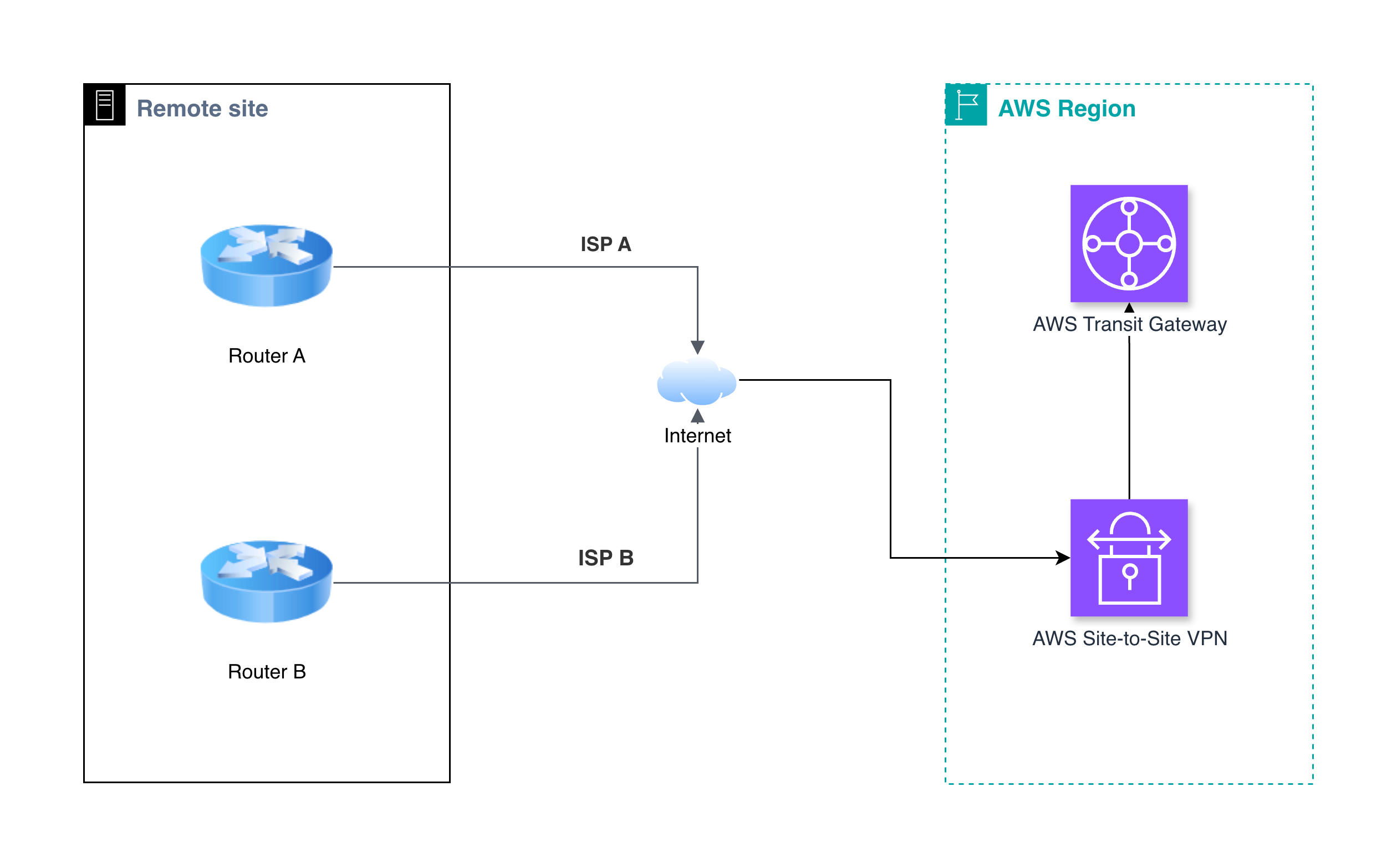
Figure 1: Two terrestrial ISPs on physically separate paths providing genuine path diversity to an AWS Region
This pattern works well when:
- Two or more terrestrial ISPs serve the area on physically separate infrastructure.
- The site needs high bandwidth (hundreds of megabits or gigabits).
- The site needs resilience against a single fiber cut or provider outage.
One terrestrial connection with cellular or satellite backup
This pattern is for sites that have one terrestrial ISP and need to add resilience through a physically independent backup path. Satellite is inherently diverse from terrestrial infrastructure because it uses a completely different physical path (orbital constellation rather than ground-based fiber or cable).
Cellular (LTE or 5G) can provide diversity but requires verification because cell towers often connect back to the carrier’s network over the same fiber lines that local ISPs use, and they’re sometimes powered by the same electrical grid. If your terrestrial ISP and the local cell tower share the same fiber route, a single fiber cut can take both down.
The terrestrial connection serves as the primary path. It typically provides more bandwidth (tens of megabits to gigabits depending on the provider) and more consistent latency. Cellular backup provides dozens of megabits to a few hundred megabits. LTE coverage reaches the vast majority of the US population, though coverage of land area, particularly in rural regions, is significantly lower. Satellite connections cover nearly any location with sky visibility. Bandwidth is often in the hundreds of megabits and is improving quickly.
A site could use both cellular and satellite as backup paths for additional diversity. The following diagram shows a primary terrestrial connection with cellular backup.
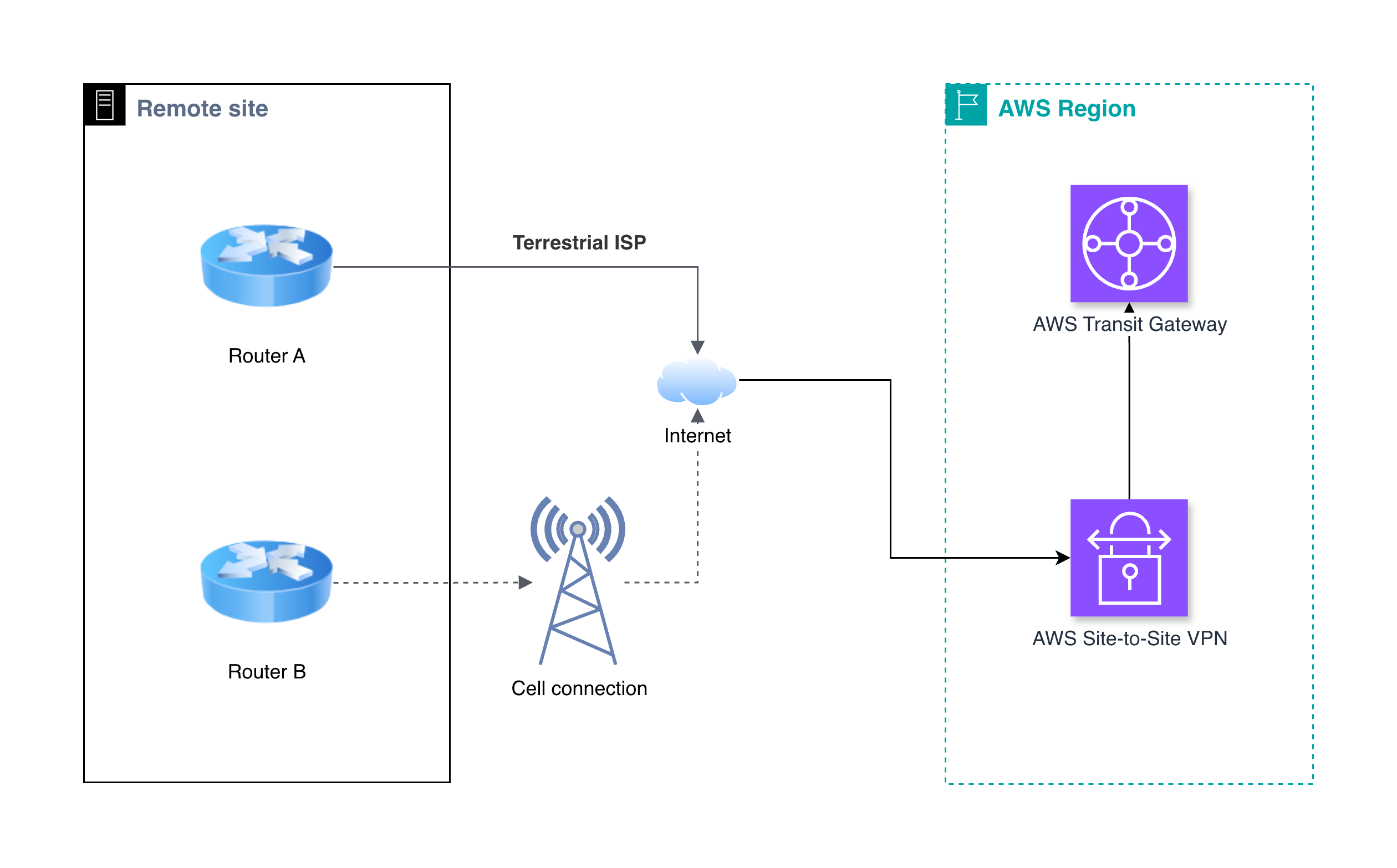
Figure 2: A terrestrial ISP as the primary connection with a cellular backup path for resilience
This pattern works well when:
- Only one terrestrial ISP serves the area (or multiple ISPs share the same physical path).
- The site needs resilience beyond what a single terrestrial connection provides.
- Cellular coverage or sky visibility (for satellite) is available at the site.
No terrestrial connection available
This pattern is for sites with no viable terrestrial broadband option. The site builds connectivity entirely from cellular and satellite connections. This is becoming increasingly practical as LTE, 5G, and LEO satellite bandwidth continues to improve.
The architecture combines multiple wireless paths for both bandwidth and resilience. Ideally, the site uses cellular connections from multiple carriers (where the carrier’s tower infrastructure is independent) plus one or more LEO satellite connections. Fixed wireless (point-to-point or point-to-multipoint radio links) can serve as an additional path where line-of-sight to a provider’s tower is available; alternatively, the organization can deploy a point-to-point link to the site.
Cellular from carrier A plus cellular from carrier B plus LEO satellite can give three physically independent paths. Adding fixed wireless (if available) provides an additional independent path.
Bandwidth at these sites is constrained further than terrestrial-connected sites. Cellular provides dozens of megabits to a few hundred megabits per carrier. LEO satellite provides bandwidth in the hundreds of megabits. Fixed wireless varies widely based on distance and equipment but can range from tens of megabits to a gigabit or more over short distances. The following diagram shows a fully wireless connection.
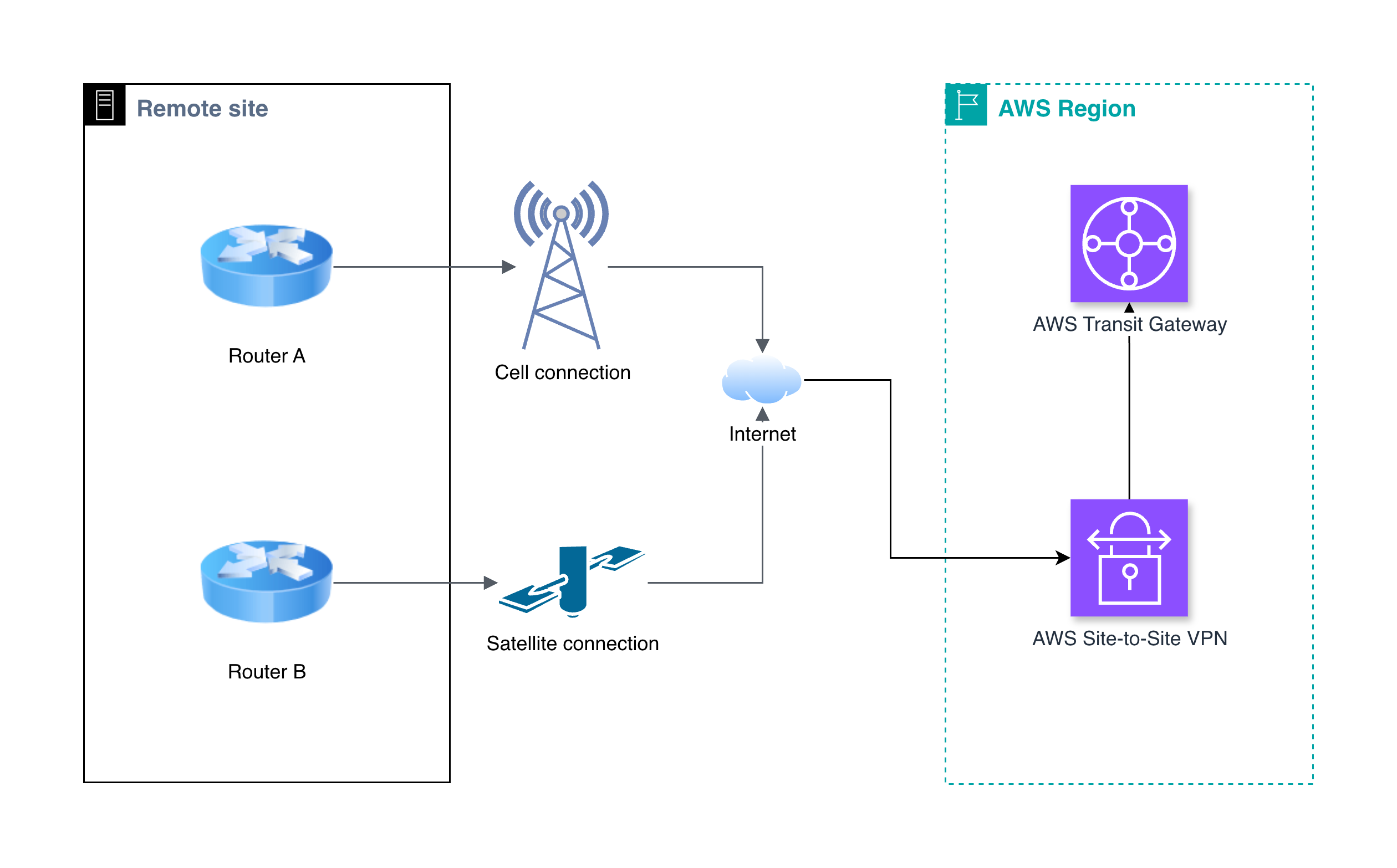
Figure 3: A fully wireless site using cellular and LEO satellite connections with no terrestrial dependency
This pattern works well when:
- No terrestrial broadband serves the area.
- The site can be served with lower bandwidth (dozens to hundreds of megabits).
- The site is in a remote location where fiber or cable buildout isn’t planned.
- Cellular coverage from at least one carrier is available or sky visibility for satellite exists.
Access patterns
Access patterns describe how your applications connect to AWS over the transport layers described in the previous section and how they handle outages in the network transportation. The two most common patterns are direct HTTPS access to public AWS endpoints and private access through encrypted VPN tunnels to private resources in your Amazon Virtual Private Cloud (Amazon VPC) setup.
Direct HTTPS access
This pattern is used for workloads accessed through a web browser or API calls over HTTPS. HTTPS access is the simplest and most preferred method for accessing resources in AWS. No VPN or site-level network configuration is required. Users access AWS hosted applications the same way they access any website. Traffic goes directly to AWS service endpoints over whatever internet connection is available. TLS encryption is used to keep data private.
Failover at this layer can be straightforward. When one transport path fails (for example, a fiber cut or cellular outage), the site’s router or software-defined wide area network (SD-WAN) device routes HTTPS traffic over the next available path. No VPN tunnels need to be reestablished, and no special hardware is required. Failover is typically very fast because the only change is which physical path carries the traffic
To improve performance in sites geographically distant from AWS Regions, organizations can use Amazon CloudFront to cache content at edge locations close to the user and AWS Global Accelerator to route traffic onto the AWS backbone at the nearest edge location, reducing latency and jitter over variable-quality paths. Both services work without any special configuration at the customer site.
This pattern works well when:
- Users access software as a service (SaaS) applications hosted on AWS, for example, case management, document storage, or call centers using Amazon Connect Customer.
- The agency consumes AWS services through HTTPS APIs, for example, Amazon Simple Storage Service (Amazon S3) uploads, Amazon Connect Customer, or public websites.
- Security requirements allow for encryption of traffic with TLS compared to requiring a dedicated VPN between on-premises systems and AWS.
Examples of this type of workload include:
- Cloud-hosted email and productivity tools
- Public-facing informational websites
- Document management and records systems accessed through a browser
- Cloud backup with Amazon S3
- Call centers such as those using Amazon Connect Customer
AWS Site-to-Site VPN with multi-connection resilience
This pattern extends your on-premises network into AWS over encrypted VPN tunnels. A VPN creates a private network path between your site and Amazon VPC, meaning traffic between your on-premises systems and AWS travels over an encrypted tunnel rather than the open internet. This is required when applications need private IP connectivity to resources in your virtual private cloud (VPC). Special considerations must be made so that the VPN connections remain up even during transport disruptions.
The most common implementation is when there is one VPN connection per transport path. Each transport path at the site gets its own AWS Site-to-Site VPN connection, all terminating on AWS Transit Gateway. Each VPN connection creates two tunnels in separate Availability Zones. A site with two transports has four tunnels. A site with three has six. If any one transport fails, only the tunnels on that path go down. The remaining tunnels continue operating.
To automate routing during failure, you can use Border Gateway Protocol (BGP). In this pattern, each VPN tunnel uses dynamic routing through a BGP session between your on-premises router and Transit Gateway. When a transport path fails, the BGP sessions on those tunnels drop, routes withdraw, and traffic shifts to the surviving paths automatically. You control which path is preferred during normal operation (for example, terrestrial as primary, cellular as backup) through BGP path attributes.
This pattern extends your on-premises network into AWS over encrypted VPN tunnels. We recommend this pattern when private connectivity to AWS is a requirement. Traffic between your on-premises systems and AWS travels over an encrypted tunnel rather than the open internet. This is useful when applications need private IP connectivity to resources in your virtual private cloud (VPC). Special considerations must be made so that the VPN connections remain up even during transport disruptions.
In any of these deployments, the on-premises router is a point of failure. Transport diversity doesn’t help if all VPN tunnels terminate on one device. For sites where device failure is an unacceptable risk, deploy multiple routers in a high-availability configuration, each connected to all transport paths. The following diagram shows a connection with independent transport paths.
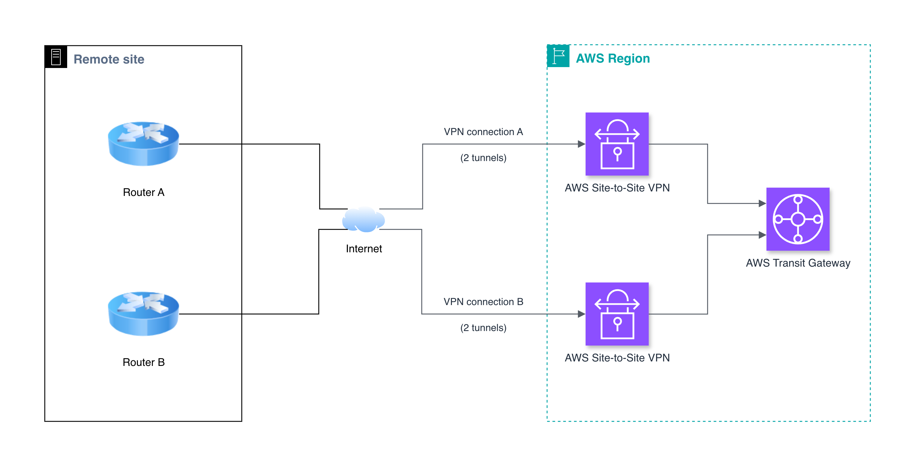
Figure 4: Two independent transport paths with an AWS Site-to-Site VPN connection that has two VPN tunnels, terminating on AWS Transit Gateway
This pattern works well when:
- Applications require private network connectivity to resources in your VPC.
- The agency runs hybrid workloads that communicate between on-premises systems and AWS.
- Automated failover across transport paths is required without manual intervention.
Examples of this type of workload include:
- Internal tools for staff (HR systems, intranet, and file shares)
- Active Directory extension to AWS
- Core line-of-business applications (permitting, utility billing, and records management)
- Database replication between on-premises and AWS
- VoIP or unified communications
Understanding single points of failure
A single point of failure is any component in your connectivity architecture where one failure takes you offline. Identifying these is the core exercise in choosing a connectivity pattern.
Sometimes, single points of failure in a network might be hidden or abstracted, so confirmation that network paths take truly diverse paths is vital. For example, multiple ISPs can use the same pole or conduit, so a network that uses two ISPs but doesn’t have confirmation of diverse paths could contain a single point of failure. Or, a network that has multiple fiber links connecting to a single router or VPN appliance with no failover could lead to a single point of failure.
The following diagram shows false diversity, where a single router connects to two ISPs that share the same physical infrastructure, compared with true diversity, where separate routers connect through fully independent ISP infrastructure.
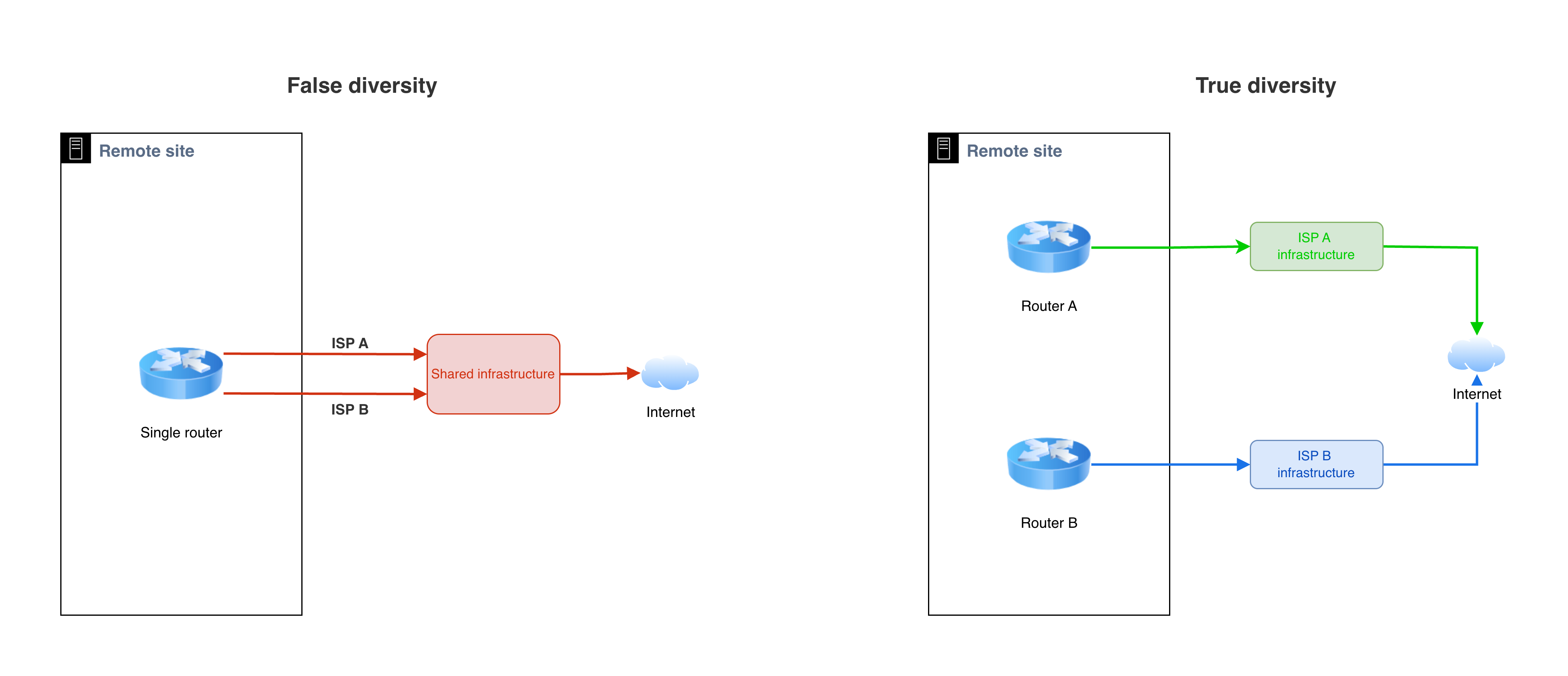
Figure 5: False diversity compared with true diversity
Conclusion
Connectivity is a vital consideration for rural and less-connected agencies. In ideal networks where multiple fiber links are available, redundancy can be easier. But for rural agencies and organizations, there are still multiple viable paths to build a highly resilient architecture. The patterns in this post describe many internet transport methods, providing agencies with strategies to support mission-critical workloads in AWS no matter their physical location.
Start by identifying which transport pattern matches what terrestrial connections are available at each site. Then choose the access pattern that matches your workloads. For sites running browser-based applications, direct HTTPS access keeps the architecture straightforward. For sites that need private network connectivity, Site-to-Site VPN with multiple connections across your transport paths provides automated resilience.
The key architectural decisions are what transport types are available at each site, which of those are physically independent from each other, and what happens to your operations when connectivity fails. The answers map directly to the patterns described in this post.
For agencies with public safety or life-safety workloads that require the highest levels of connectivity resilience, refer to Resilient public safety connectivity models in AWS for architectures built around AWS Direct Connect with carrier and geographic redundancy.