AWS for Industries
Physical AI Production Designer: Cell Programming from Weeks to Hours
Programming a single robotic production cell can take weeks, and complex operations can include hundreds of cells. Today, we’re announcing Physical AI Production Designer on AWS, a new AWS solution that helps manufacturing and automation engineers reduce robot cell programming time. Instead of programming each robot by hand, engineers define the production task from their existing product lifecycle management (PLM) data. AI agents then plan the cell, generate native programmable logic controller (PLC) and robot code for each vendor, and validate that code on the vendors’ virtual controllers before it reaches the shop floor.
We built the solution with a global manufacturer that is working to make AI part of its core manufacturing operations rather than a set of isolated pilots. In this post, the first in a series, we explain the challenge the solution addresses, how it works, its architecture on AWS, and how to get started.
The challenge: handoffs between disconnected tools
The industrialization workflow that puts a new product into production has worked for decades, yet shopfloor production engineering has remained largely unchanged. The core process is manual, fragmented, and disconnected from the reality of the factory floor. From product definition to the first good part off the line, every program passes through a chain of handoffs, with each stage owned by a different team, a different tool chain, and a different mental model of the cell:
- Product definition (PLM) — Components, specifications, materials, and process requirements are captured in the product lifecycle management system, establishing what needs to be built.
- Cell and tooling selection — Engineers map those requirements onto predefined layouts, standard cells, fixtures, and end-effectors, deciding how the product will be built.
- Line layout and simulation — Engineers arrange the selected cells into a production line and simulate material flow and line balancing to validate throughput at the system level.
- Cell simulation and robot programming — Inside each cell, engineers program robot paths and interlock one arm at a time, verifying that motions are collision-free and cycle times are met.
- PLC and robot code generation — Programmers translate the validated sequences into executable code, written per vendor and per controller, because no universal language spans them.
- Program adjustment on the line — Where simulation finally meets reality: engineers tune code, correct timing, and rework interlocks against real equipment during ramp-up.
Each step consumes the output of the one before it, yet none feeds information back. Workflows in one direction only, and with every handoff, information is lost: engineers re-enter it by hand, without context, and validate it from scratch.
For a complex product such as a car body, this chain of handoffs can take years, and the costs compound. A single body-in-white line, the stage in automotive manufacturing where the car body frame is joined together, can comprise up to fifty robotic cells with each containing multiple arms that must be programmed, interlocked, and validated individually. For the global manufacturer we worked with on this solution, programming just one robotic cell could take up to eight weeks. The same is true of every incremental change, whether it serves continuous improvement or a broader product mix: each one runs through the same process, which erodes the return on the automation investment. Multiply that by fifty, and these manual handoffs constrain innovation and delay the time to market of new products, variants, and features.
The last task, adjusting programs on the physical line during ramp-up, is where much of the real engineering happens, precisely because it is the first moment the full system is tested. Its outcome depends heavily on the experience of the commissioning engineer. The knowledge that makes ramp-up work is tacit, accumulated through years of hands-on problem solving, and it is applied in the moment as effective troubleshooting rather than encoded into the production system.
This dependence on tribal knowledge is hard to sustain: up to 1.9 million U.S. manufacturing roles may go unfilled by 2033, and automation engineers remain among the hardest to hire and retain. Generative AI looks like an obvious way to stretch that scarce capacity, but code generation alone does not close the gap. Without testing against a physical model, compiled code can still violate an interlock and cause equipment collisions.
Why faster individual stages are not enough
The prevailing assumption in robotic cell deployment is that accelerating any single stage of the process (whether design, offline programming, or commissioning) will compress the overall schedule. It does not. The true bottleneck is not the duration of individual stages, but the friction generated at the handoffs between them. Each transition from one tool to another, from one team to the next, forces engineers to re-enter and re-validate the same data, compounding delays that local optimization alone cannot absorb.
This handoff friction results in four persistent symptoms:
- Sim-to-real gap – the distance between what was simulated in a virtual environment and what is actually executed on the factory floor. Because PLC logic and robot code encounter real equipment for the first time on site, errors surface at the point where they are most expensive to diagnose and most disruptive to correct.
- Conservative interlocking – Because no one can prove that a tighter motion sequence is safe on a running line, engineers default to generous wait times and wide safety margins. These margins stack, eroding throughput for the entire operational life of the cell.
- Data re-entry – Re-entry turns every handoff into an opportunity for transcription errors and rework.
- No cross-platform standard – Without a common programming model that spans robot manufacturers, programs written manually in each vendor’s proprietary language cannot be transferred or reused. Every new platform demands its own bespoke development effort, and every multi-vendor line multiplies the cost of every change.
Compounding the problem, the expertise that makes this painstaking work possible resides in people rather than in systems. A seasoned programmer’s intuition about how to approach an awkward weld or sequence a tight cell lives in that person’s head, undocumented and irreplaceable. That knowledge leaves the organization the day they do.
Solution Overview: Physical AI Production Designer on AWS
The research community has a name for what manufacturers need: adaptive manufacturing – a production system capable of reconfiguring itself in response to a change in the product. At its core sits the product–process–resource model, which establishes a causal chain: the product definition determines the required processes, and those processes in turn dictate how the physical resources on the factory floor must behave. Until this causal chain is encoded in a system rather than in a person’s head, the handoff problem, the sim-to-real gap, and the loss of institutional knowledge will persist with every new program, every line changeover, and every cell redesign.
Physical AI Production Designer encodes this causal chain to reduce silos and handoffs: the product program becomes the input, and an adaptable, AI-optimized production process is the output. The engineer states the intent. An agent drives the engineering modules to produce a cell scene, a motion plan with its interlock map, and the native PLC and robot code. The engineer then reviews in 3D and approves. This can help teams plan, validate, and optimize a cell in hours instead of weeks.
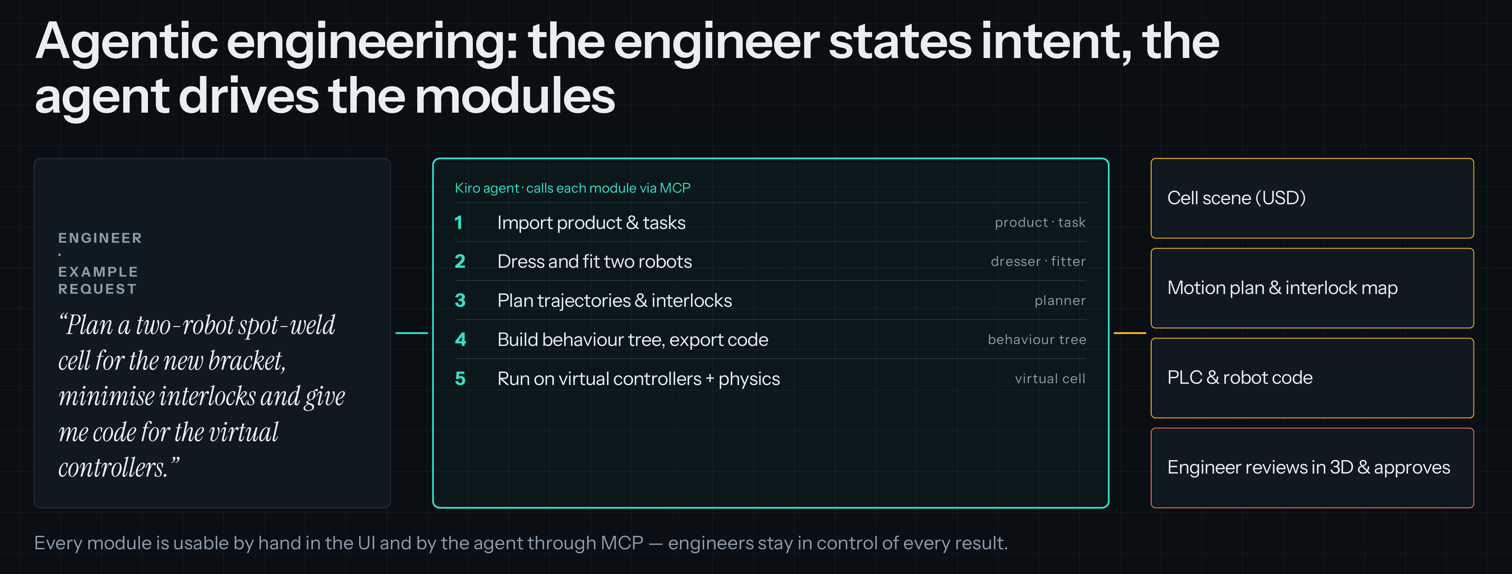 Figure 1: Agentic engineering workflow
Physical AI Production Designer addresses the traditional process design challenges not as a monolithic platform but as four composable components that share a single engineering flow. Each component can evolve independently, yet because every component reads from and writes to the same product-centric model, the engineer works in one continuous thread from cell layout to deployed code with minimal re-entry, translation, or handoffs. The capabilities are:
- A single tool for building a simulation environment. The solution assembles product data, fixtures, robots, and end-effectors into a cell in a single environment, from the plant’s PLM data, instead of requiring re-entry across a chain of tools. This reduces handoffs.
- Trained and calculated, optimized cell activities and robot trajectories. Solvers compute task allocation, sequence, collision-free trajectories, and interlocks instead of engineers deriving them by hand, and for high-changeover products a policy is trained on a parameterized cell. Interlocks can be set close to geometric limits instead of padded for caution. This replaces conservative, hand-set interlocks with computed ones.
- Validation in a virtual environment that runs the real code and components, not a simulation of them. The PLC and robot programs that will ship run unchanged on the vendors’ own virtual PLC and virtual robot controllers, connected by an emulated fieldbus, against a physics model. Because the output is each vendor’s native code, you keep your existing controllers and runtimes and there is no vendor lock-in. This helps narrow the sim-to-real gap and supports virtual commissioning instead of time-consuming post-deployment troubleshooting.
- Bidirectional communication with the shop floor. The same path that deploys approved programs to the physical cell brings live traces, faults, and drift back. That keeps a lightweight digital twin in sync, lets engineers dry-run a change against the real cell’s recorded behavior before it touches equipment, and turns every real fault into a new regression test.
The result is one continuous agentic engineering flow that collapses weeks of sequential handoffs, re-entry, and on-site debugging into hours of intent-driven, validated programming.
How it works: seven steps from PLM to production
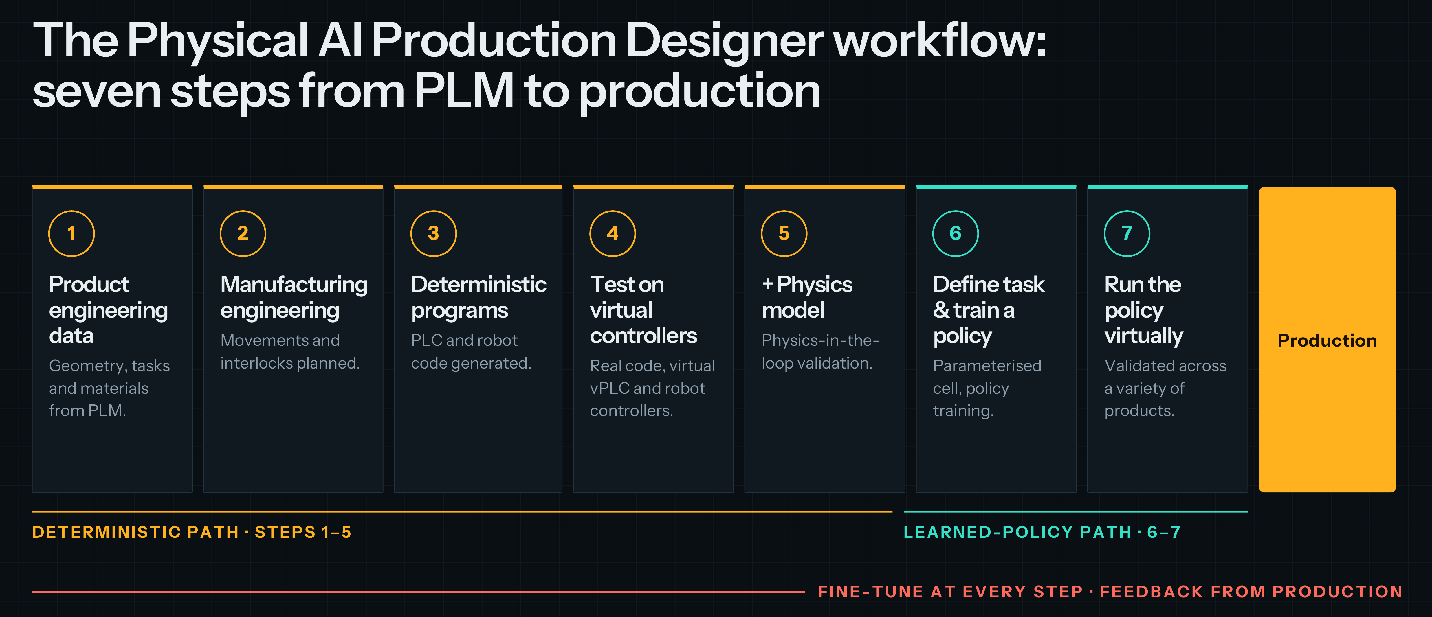 Figure 2: The Physical AI Production Designer workflow
The Physical AI Production Designer workflow in Figure 2 offers two paths from the same product data to the same production cell.
The deterministic path: code for the shop-floor cell
The goal of the deterministic path is a set of native PLC and robot programs that can be deployed to the physical cell and run there as validated in the virtual cell.
- (1) Product engineering data. The solution imports the product definition from PLM into a single environment. This includes part geometry, process tasks (for example, the list of spot welds and their locations), and material specifications. Together, these describe what needs to be built and the operations required to build it.
- (2) Manufacturing engineering data. The solution then adds the production resources: fixtures, robots, and end-effectors such as weld guns and grippers. Combining these with the product data in the same environment builds a digital model of the cell, which captures how the product will be built.
- (3) Deterministic programs. The agent compiles the plan into native head-PLC code and native robot programs in each vendor’s language; the same artifacts a programmer would otherwise write.
- (4) Test on virtual controllers. The generated code runs unchanged on the vendor’s virtual PLC and virtual robot controllers, connected by an emulated fieldbus, so the logic, handshakes, and interlocks are tested against the real control software.
- (5) Add the physics model. The same code runs again with physics in the loop. A kinematic viewer only draws what you already computed; a physics engine can report that link 4 of robot 2 hit a fixture at 12.4 seconds, which the planner did not predict. Virtual commissioning substitutes for line time only if the simulator can contradict you.
- (8) Approve and deploy. The engineer reviews the test evidence and approves the validated program set for deployment to the physical cell.
The output is a validated program set that the plant’s existing controllers execute deterministically, cycle after cycle.
The learned-policy path: real-time adaptive control
The learned-policy path is a parallel alternative to step 2 and 3. Instead of calculating one fixed plan and trajectory set in advance, the task is defined on a parameterized cell, and a policy is trained to produce the motion itself, in real time, from the current state of the cell.
- (6) Define the task and train a policy. Scene parameters such as part variants, positions, and tolerances are varied, and the policy learns to perform the task across all of them.
- (7) Run the policy virtually. The trained policy drives the robots on the same virtual controllers and physics model used in steps 4–5 and is validated across a variety of products before it is promoted.
This path suits cells with frequent changeovers or high product variety, where re-planning and re-generating code for every variant is the bottleneck. On the shop floor, the policy runs on a cell controller next to the line and steers the robots in real time, while the safety functions stay on the certified safety PLC.
Production and the way back
Both paths end in production. The orchestrator deploys approved programs and policies to the physical cell, and live traces and faults flow back to fine-tune every earlier step.
Every engineer and every agent gets their own virtual cell, built from a cell definition held in GitHub, so instances are reproducible. Cells are disposable and run in parallel: ten engineers, or a hundred agent iterations, each get their own, with no queue for a shared test bench. The same cell serves the whole lifecycle, from validating a concept during quotation, through daily regression testing and full virtual commissioning, to running as a production shadow next to the physical cell.
Most plants have cells that have been running for a decade, so Physical AI Production Designer can also start by extracting their robot programs, layouts, and process data. parsing vendor robot programs and IEC 61131-3 PLC logic, and recording joint values from PROFINET traffic. The extracted cell calibrates the virtual cell against reality and becomes the regression suite that generated code is judged against. This ground truth is what makes generated code trustworthy.
High-level architecture overview
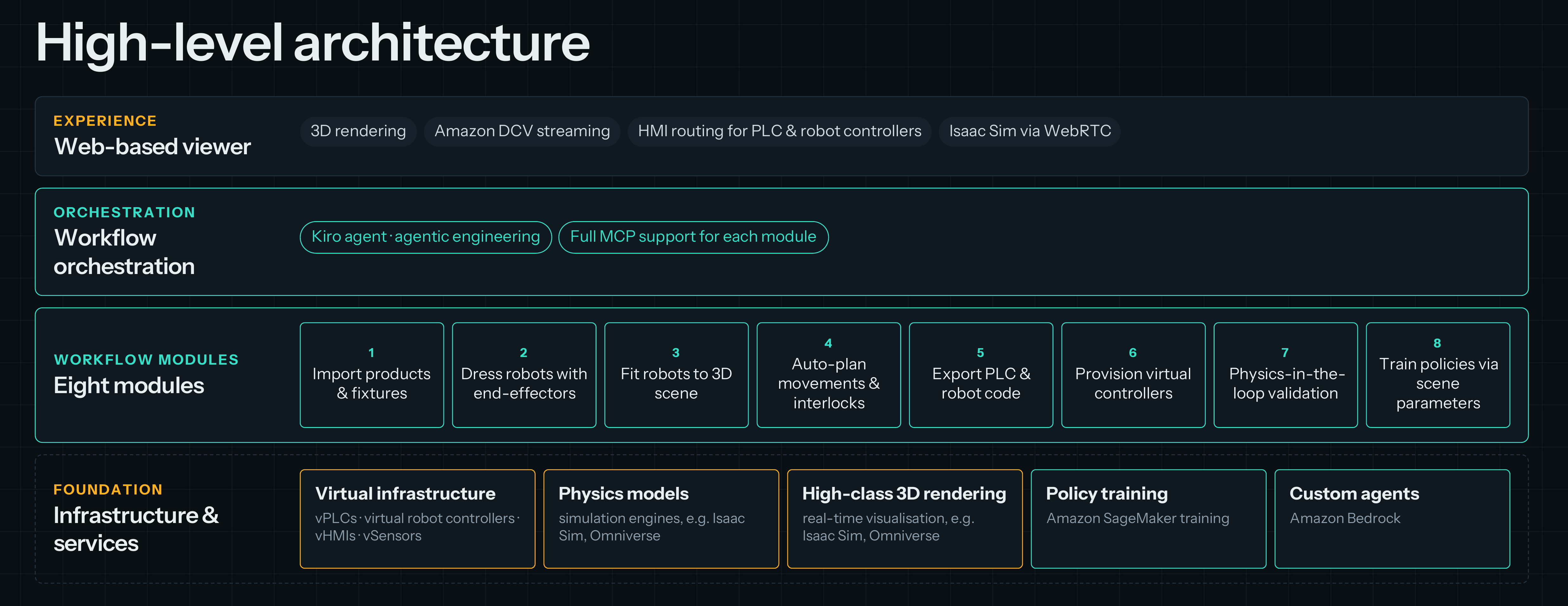 Figure 3: The four layers of Physical AI Production Designer on AWS — experience, orchestration, workflow modules, and foundation.
Physical AI Production Designer is organized in four layers:
- Experience — a web-based viewer. Engineers work in the browser: 3D rendering of the cell, Amazon DCV streaming of the vendor engineering tools, HMI routing to the PLC and robot controllers, and the physics simulator streamed over WebRTC.
- Orchestration — workflow orchestration. A Kiro agent performs agentic engineering across the workflow, and every module exposes a full Model Context Protocol (MCP) interface, so the agent and the engineer drive the same modules.
- Workflow modules — eight modules. (1) import products and fixtures, (2) dress robots with end-effectors, (3) fit robots to the 3D scene, (4) auto-plan movements and interlocks, (5) export PLC and robot code, (6) provision virtual controllers, (7) physics-in-the-loop validation, and (8) train policies via scene parameters.
- Foundation — infrastructure and services. Virtual infrastructure (vPLCs, virtual robot controllers, vHMIs and vSensors), physics models and high-class 3D rendering (for example NVIDIA Isaac Sim and Omniverse), policy training on Amazon SageMaker AI, and custom agents on Amazon Bedrock.
From CAD design to simulation-ready cell
Before an agent can plan anything, the cell needs to exist as a simulation environment. In most projects, building that environment is itself weeks of manual work: exporting CAD, cleaning up geometry, adding collision shapes, placing robots, and wiring up controllers. Physical AI Production Designer replaces that work with a browser-based engineering workspace that does the conversion for the engineer and asks for input only where a decision is needed.
The engineer starts from the designs that already exist. The engineer imports product geometry, bills of materials and process tasks from PLM, together with the CAD models of fixtures, tooling, and end-effectors. The import module converts them into a single cell scene in Universal Scene Description (USD), deriving the collision geometry and physical properties the simulator needs, so the engineer does not rebuild the cell by hand in a separate simulation tool.
The workspace then assembles the cell. The workspace takes robots from the vendors’ models, dresses them with their end-effectors, and fits them into the 3D scene at positions where they can reach their tasks, with reachability computed rather than guessed. When the scene is ready, the matching virtual PLC and virtual robot controllers are provisioned and connected automatically, so the result is not only a 3D model but a cell that can run real control code.
Every step can be driven by the agent through MCP or done by hand in the UI, and the engineer stays in the loop where it matters: reviewing the scene in 3D, correcting a fixture position or a robot mounting, and approving the result. In the same workspace the engineer can see the cell in 3D, follow the behavior-tree plan, watch PLC and controller status through the virtual HMIs, open the vendor engineering tools streamed through Amazon DCV, and talk to the agent. The scene, the cell definition, and every change to them are versioned in GitHub, so the simulation environment is reproducible and becomes the starting point for every variant that follows.
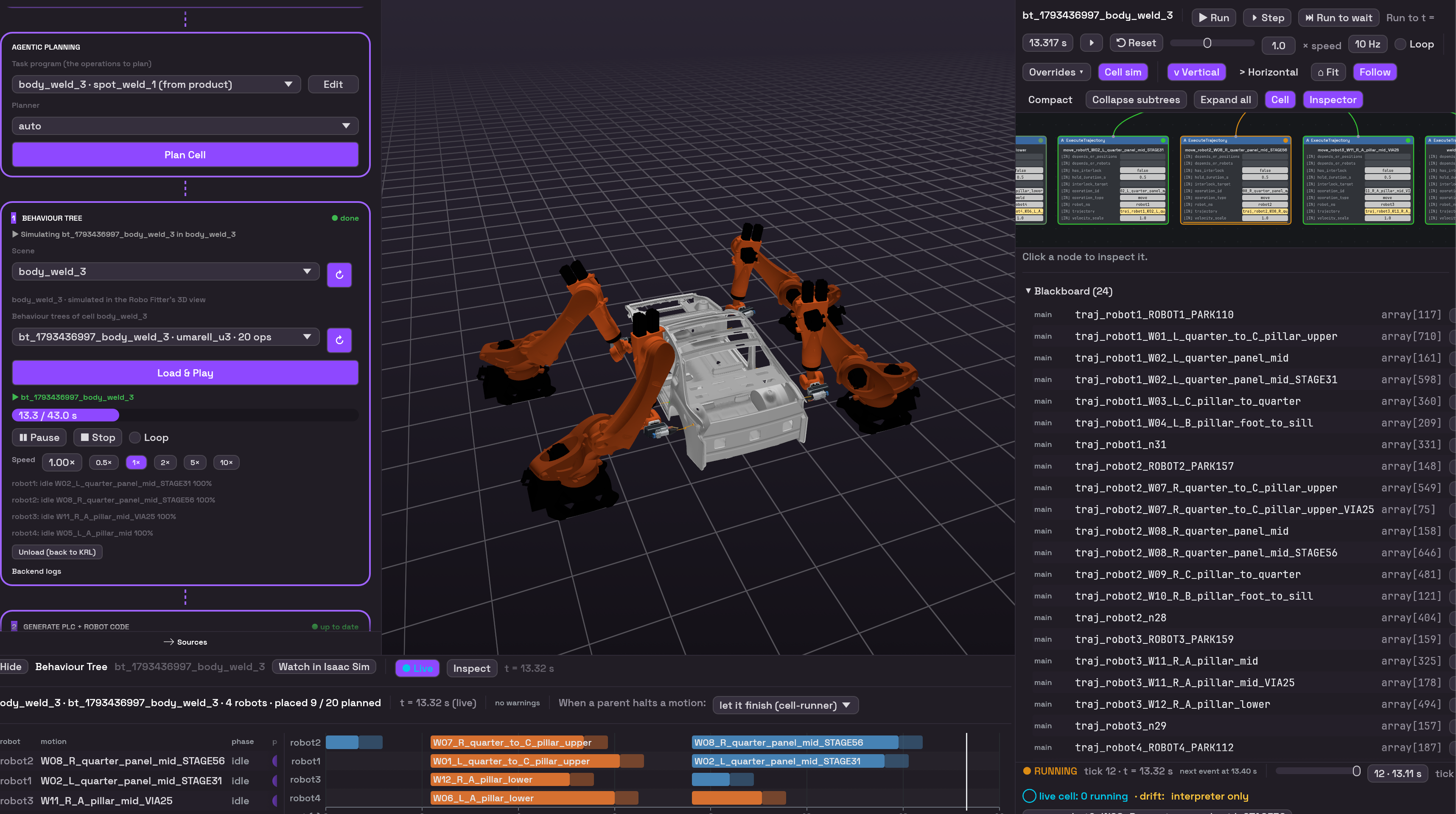 Figure 4: Physical AI Production Designer workspace in browser – 3D cell view, behavior tree plan, PLC status, and agent chat
Agents that plan the cell
The planning agents turn a product and process specification, for example a list of spot welds on a car door, into the plan for a multi-robot cell: which robot takes which weld, in what order, along which collision-free trajectories, and with which interlocks to keep arms with overlapping workspaces apart. The plan is expressed as a behavior tree, a structure both an engineer and a compiler can read.
One design rule runs through every component: put the judgment in the model and the arithmetic in a script. A large language model, accessed through Amazon Bedrock, chooses an approach strategy for an awkward weld, sets the weights that trade cycle time against heat distribution across a panel, or decides that a cell’s geometry favors rotating a robot outward. Deterministic solvers then compute the inverse kinematics, the collision-free paths and the clearance at every timestep. The test for which side a task belongs on is this: would a wrong answer be distinguishable from a right one? If a solver can check it, the model should not be asked to assert it.
Because a plan is a computation and not a hand-tuned artifact, the agents can compare many alternatives, robot counts, mounting positions, task allocations, sequences, and keep the one with the shortest cycle time and the fewest interlocks. For high-changeover cells, the same parameterized scene becomes the training ground for a policy on Amazon SageMaker.
Engineering know-how is captured as skills: versioned packages of instructions, scripts, and reference material that agents load when they need them. A veteran’s approach to an awkward weld becomes reviewable, versioned, and inherited by every cell in the network. Failure handling is a skill too. When the motion planner cannot reach a weld, it reports a machine-readable reason, such as the goal being 31 mm inside a fixture rail, and the agent changes one thing and tries again. Some fixes are never allowed, for example the recovery process may refuse to relax a weld orientation to make a plan and pass, so it escalates to a human instead.
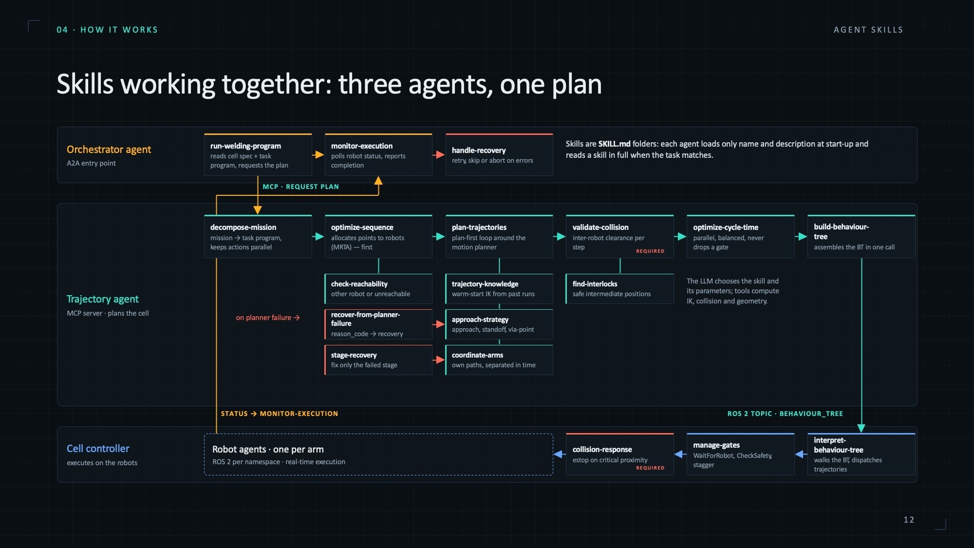 Figure 5: Physical AI Production Designer Agentic Workflow Diagram
Agents that write the cell’s code and test it
Once the trajectories and the behavior tree are fixed, the agents compile the plan into native PLC logic and robot programs. In our first implementation, that means IEC 61131-3 code for the cell’s main PLC and programs in the robot vendor’s own language. A vendor-neutral motion program sits between the plan and the robot code, so supporting another robot language means writing an adapter, not a rewrite.
The generated code then goes through three checks, and each one catches problems the one before can miss. First, the vendors’ own compilers run headless, so the code builds exactly as it would in the vendor’s tool. Next, linters and formal model checking catch logic and interlock errors that still compile cleanly. Finally, closed-loop tests run the PLC and robot programs together in a fresh virtual cell, using the vendors’ real runtimes. These tests include injected faults, such as a sensor that never reports or a robot that stops mid-path.
When a check fails, the result goes back to the agent, which repairs the code until it passes. Each candidate then reaches a human as a Git pull request with the full test evidence attached. The code has already passed closed-loop tests on the real control software, so the engineer reviews evidence, not a suggestion. That’s the key difference from vendor copilots, which offer suggestions inside a single vendor’s tool.
A governed path from virtual to physical
A system that writes robot programs at machine speed can also write a wrong robot program at machine speed. That risk shapes the architecture. Physical AI Production Designer is split into two domains with a single boundary between them:
- The simulation domain is where artifacts are cheap, wrong, and iterated. It is deliberately ungated, so agents and engineers can run thousands of experiments.
- The physical domain runs approved programs on the controllers the plant already owns, with deterministic cycle times against certified safety PLCs, integrated over OPC UA, PROFINET and vendor protocols.
- An orchestrator is the sole gatekeeper between them. Every PLC program, trajectory, and policy passes its validation gates before it reaches physical equipment, and everything else is denied by default.
A single gatekeeper is a deliberate design choice: if three components can each push code to a robot, you need three review processes instead of one. With one, the gates can be tested and audited. Promotion follows GitOps practices: sign-off in the virtual cell, engineer and safety approval, KPI verification after deployment, and rollback to the last approved release. Humans gate the boundary, not the sandbox, because a system that needs approval for every simulation run gets bypassed.
Physical AI Production Designer doesn’t replace your functional safety process. Safety functions remain on your certified safety PLC. You’re responsible for risk assessment, safety certification, and final approval of every program before it runs on physical equipment.
The loop also runs in reverse. Production traces and real faults flow back to the orchestrator, which detects drift between what was promoted and what happened, keeps the digital twin in sync, and turns real faults into new regression tests. The sim-to-real gap narrows not because the simulator is perfect, but because the physical domain reports back.
Built on AWS
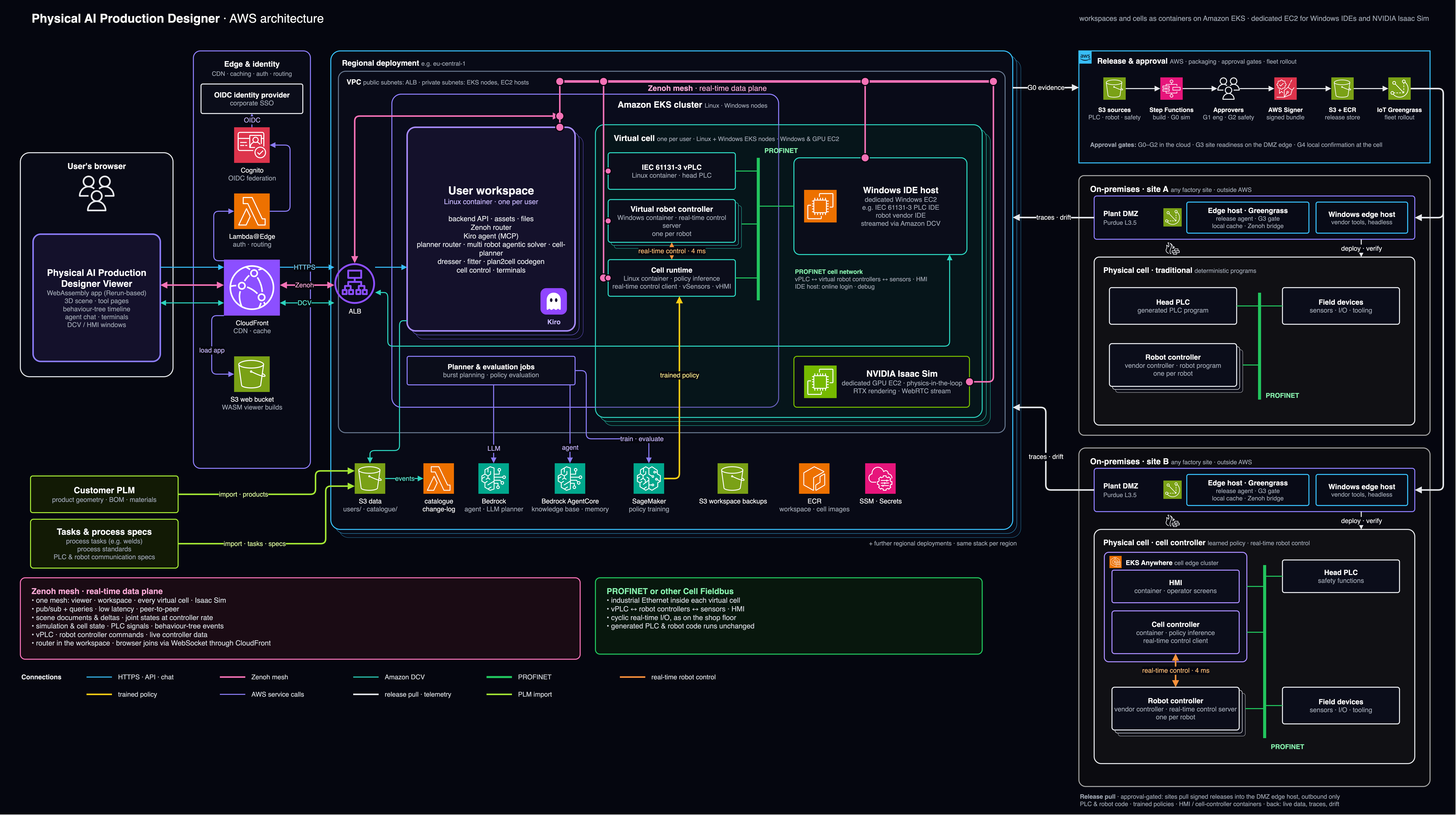 Figure 6: Physical AI Production Designer on AWS architecture
Experience. The solution’s web viewer is a WebAssembly application served from an Amazon S3 bucket through Amazon CloudFront. Engineers sign in with corporate single sign-on federated through Amazon Cognito as the OpenID Connect (OIDC) provider, and Lambda@Edge handles authentication and routing at the edge. Behind an Application Load Balancer, the browser receives three streams: HTTPS for the API and agent chat, a real-time data stream for the 3D scene, and Amazon DCV sessions for the vendor engineering tools and HMIs.
Orchestration. Each engineer gets a user workspace, one Linux container per user on Amazon EKS, holding the backend API, assets and files, the Kiro agent with its MCP connections, and the planner router. The agents reason with foundation models through Amazon Bedrock. A Zenoh mesh forms the real-time data plane that connects the viewer, the workspace, every virtual cell and Isaac Sim: publish/subscribe with low latency, carrying scene deltas, joint states at controller rate, PLC signals, behavior-tree events, and live controller commands.
Workflow modules. The modules run in the workspace as services the agent calls over MCP: the dresser and fitter that equip and place the robots, the cell planner that allocates tasks and plans trajectories and interlocks, and the code generator that turns a plan into PLC and robot code. Compute-heavy work, such asburst planning across many alternatives and policy evaluation, runs as planner and evaluation jobs on the same EKS cluster, so capacity scales with the search rather than with the number of engineers.
Foundation. Each virtual cell runs on Linux and Windows EKS nodes: the Virtual PLC as a Linux container running the head PLC, one Robot VirtualController Windows container per robot with its real-time RSI server, and a cell runtime container that hosts policy inference, the RSI client, virtual sensors and the virtual HMI. A PROFINET cell network connects them exactly as on the shop floor, with cyclic real-time I/O, so the generated PLC and robot code runs unchanged. A dedicated Windows EC2 host runs the vendor IDEs (for example the CODESYS IDE and KUKA WorkVisual) for online login and debugging, streamed through Amazon DCV. NVIDIA Isaac Sim runs on dedicated GPU EC2 instances for physics-in-the-loop validation and RTX rendering, streamed over WebRTC. Amazon SageMaker trains and evaluates policies and hands the trained policy to the cell runtime. Product geometry, BOMs and process tasks are imported from the customer’s PLM into Amazon S3, where an AWS Lambda function records catalog changes; workspaces are backed up to S3, container images for workspaces and cells live in Amazon Elastic Container Registry (Amazon ECR), and secrets are held in AWS Systems Manager, so no instance needs SSH or RDP open to the internet. The whole stack is defined as infrastructure as code with the AWS Cloud Development Kit (AWS CDK) and can be deployed as the same stack in further AWS Regions, close to each production network.
Virtual to physical. On premises, the two domains meet the two kinds of cell a plant runs. A traditional cell receives the generated head-PLC program and obot programs over PROFINET, with deterministic programs on the existing Robot controllers. A cell-controller cell adds an edge host that runs the HMI and a cell-controller container with policy inference, steering the robots through robot RSI at a 4 ms cycle while the safety functions stay on the head PLC. In both cases, sites pull versioned, approved releases — PLC and KRL code, trained policies, and the HMI and cell-controller containers — through GitOps, and push live data, traces and drift back. Amazon EKS Anywhere and AWS Outposts can host the edge workloads that sit next to the line, and the Industrial Data Fabric on AWS can carry production telemetry back to the orchestrator.
Because cells are elastic, customers pay for validation capacity while it runs, not for idle test benches.
Business impact
Based on our work with the global manufacturer, the value of Physical AI Production Designer lands with four groups along the path from product to production.
- Manufacturing engineers – They no longer move a cell through a chain of tools. They plan it in one environment, directly from PLM data, with reachability and interlocks computed rather than estimated. In our work with the manufacturer, the team estimated this shortens the planning cycle from 24 to 15 months.
- Robot and PLC programmers – They shift from writing code to reviewing it. Instead of starting from scratch for every vendor and every cell, they refine generated programs that have already passed closed-loop tests, and the know-how they apply is captured as skills that every future cell inherits.
- Commissioning and operations teams – The first commissioning happens on virtual controllers, not on the line. Once the cell is running, live traces and drift detection keep its digital twin in sync with reality, which helps keep the sim-to-real gap narrow.
- Plant management – In the customer’s analysis, tighter, computed interlocks raise cell throughput by more than 10%, worth about €50M per plant.The same solution can be extended to other plants.
A good way to start is a pilot: pick a pilot cell and its product data, commission it virtually on the vendors’ virtual controllers, and measure cycle time and interlock gains against today’s baseline.
Conclusion
Physical AI Production Designer on AWS combines a high-fidelity virtual automation cell built from the plant’s real control software, AI agents that plan the cell and generate native PLC and robot code, and a governed, bidirectional GitOps path that promotes only proven changes to the physical line and brings production feedback back. Together they move automation engineering from the shop floor into the cloud, where it can run in parallel, early, and repeatably.
Physical AI Production Designer meets plants where they are. It supports today’s cell structure, a head PLC and deterministic robot programs, in each vendor’s native language, on the controllers the plant already owns. For cells with frequent changeovers, the learned-policy path trains and validates policies on the same virtual cells and deploys them through the same governed path.
This post is the first in a series. In the next post, we will take a deep dive into policies and edge control: how policies are trained on parameterized cells, validated across product variants on virtual controllers, and run safely at the edge next to the line.
To learn more about Physical AI Production Designer on AWS, or to explore a pilot for your own robotic cells, contact your AWS account team. For builders interested in diving deeper, check out the AWS Solution Guidance Physical AI Production Designer on AWS and the solution’s Github Repository.