This Guidance demonstrates how to configure a cell-based architecture for Amazon Elastic Kubernetes Service (Amazon EKS). It moves away from typical multiple Availability Zone clusters to a single Availability Zone cluster. These single Availability Zone clusters are called cells, and the aggregation of these cells in each Region is called a supercell. These cells help to ensure that a failure in one cell doesn't affect the cells in another, reducing data transfer costs and improving both the availability and resiliency against Availability Zone failures for Amazon EKS workloads.

Please note: [Disclaimer]

Architecture Diagram

[Architecture diagram description]

Download the architecture diagram PDF 
  • Main Architecture
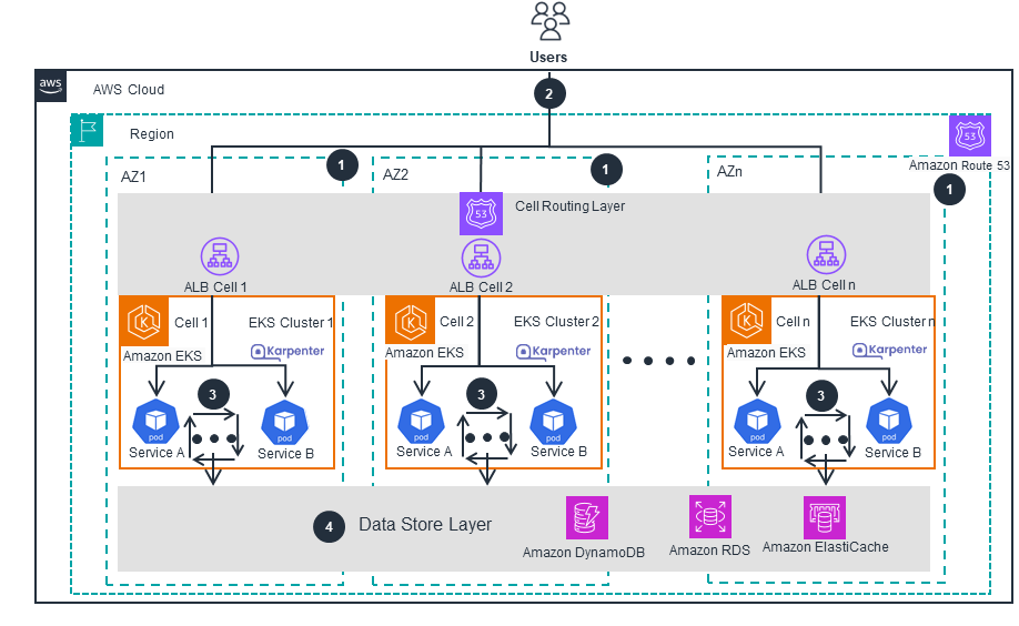
  • This architecture diagram shows how you can use a cell-based architecture to improve resiliency and reduce data transfer costs for Amazon EKS workloads. It shows what a cell consists of and how those cells are routed. For more details about supercells, open the other tab.

  • Supercells
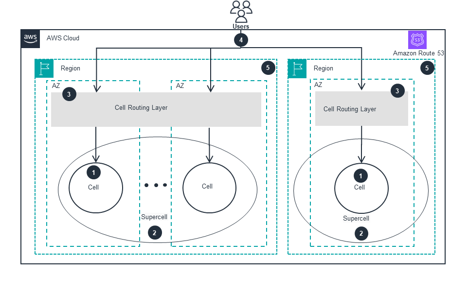
  • This architecture diagram shows how multiple cells are aggregated to create a supercell. It also outlines how those supercells are routed. For more details about the main architecture, open the other tab.

Well-Architected Pillars

The AWS Well-Architected Framework helps you understand the pros and cons of the decisions you make when building systems in the cloud. The six pillars of the Framework allow you to learn architectural best practices for designing and operating reliable, secure, efficient, cost-effective, and sustainable systems. Using the AWS Well-Architected Tool, available at no charge in the AWS Management Console, you can review your workloads against these best practices by answering a set of questions for each pillar.

The architecture diagram above is an example of a Solution created with Well-Architected best practices in mind. To be fully Well-Architected, you should follow as many Well-Architected best practices as possible.

  • When configuring this Guidance, Amazon EKS, ELB, and Route 53 work in tandem to isolate faults to individual partitions. Traditionally, users were in the same failure domain of a single business system. Now, with this new approach, users are in different failure domains, so workloads are more resilient in the rare, but possible, event of an Availability Zone (AZ) failure. 

    Read the Operational Excellence whitepaper 
  • All AWS services used in this Guidance use AWS Identity and Access Management (IAM) for authentication and authorization. These services utilize IAM roles to get short-term credentials to access other AWS resources. By scoping IAM policies to the minimum permissions required, you limit unauthorized access to resources. Also, applications running in Kubernetes' clusters can utilize native Kubernetes authentication and authorization policies to interact with the Kubernetes API server.

    Read the Security whitepaper 
  • As each Amazon EKS cell is deployed to a single AZ, multiple such cells are deployed to achieve availability against AZ-wide failures, with ELB directing traffic to healthy cells. ELB allows for synchronous loose coupling so that traffic won’t be directed to any unhealthy Amazon EKS cells. This reduces the chance of application failures. You can also use the Route 53 Application Recovery Controller to do zonal shifts, as well as the Route 53 routing control component in the Application Recovery Controller to mitigate any failures from AZs or Region-wide impairments. 

    Read the Reliability whitepaper 
  • When intra-cell traffic is kept within a single AZ, it greatly improves the network performance with low latency. A cell-based, multi-cluster architecture ensures resiliency against AZ-wide failures, improves the performance of your applications, and reduces the data transfer charges by keeping the intra-cell communications within a single AZ. For additional improvements, Kubernetes Horizontal Pod Auto Scaling can be utilized to automatically scale the applications, and Karpenter can be used for compute autoscaling within an Amazon EKS cell. Moreover, ELB ensures the traffic is distributed across healthy cells, and additional Amazon EKS cells can also be launched to match the heavy demand. 

    Read the Performance Efficiency whitepaper 
  • All the services used in this Guidance, including Amazon EKS, Amazon Elastic Compute Cloud (Amazon EC2), and ELB are managed services that offer a pay-as-you-go approach to pricing. The AWS Pricing Calculator can help you estimate the cost of these services. Kubernetes Horizontal Pod Auto Scaling and Karpenter are used to auto-scale the workloads to match the application demand, helping to secure a high utilization of deployed resources. Karpenter can also help you provision capacity from multiple Amazon EC2 instance types, such as a Spot instance and On-Demand instances, to further reduce your overall compute spend.

    Read the Cost Optimization whitepaper 
  • To help minimize the environmental impacts of running your cloud workloads, Kubernetes Horizontal Pod Auto Scaling policies were carefully selected for this Guidance due to its capability to match the number of application pods with the demand. Furthermore, Karpenter is used to launch the required compute capacity in each Amazon EKS cell, and maintains high utilization of deployed compute resources. Karpenter can also be used to provision capacity using more sustainable Amazon EC2 instance types, like AWS Graviton Processors, AWS Inferentia, and AWS Trainium, and also ensures high utilization of deployed resources.

    Read the Sustainability whitepaper 

Implementation Resources

A detailed guide is provided to experiment and use within your AWS account. Each stage of building the Guidance, including deployment, usage, and cleanup, is examined to prepare it for deployment.

The sample code is a starting point. It is industry validated, prescriptive but not definitive, and a peek under the hood to help you begin.

Containers
Blog

Life360’s journey to a multi-cluster Amazon EKS architecture to improve resiliency

This blog post demonstrates how Life360 uses a multi-cluster Amazon EKS architecture to address Amazon EKS scaling and workload management, and have a statically stable resilient infrastructure for AZ wide failures.

Disclaimer

The sample code; software libraries; command line tools; proofs of concept; templates; or other related technology (including any of the foregoing that are provided by our personnel) is provided to you as AWS Content under the AWS Customer Agreement, or the relevant written agreement between you and AWS (whichever applies). You should not use this AWS Content in your production accounts, or on production or other critical data. You are responsible for testing, securing, and optimizing the AWS Content, such as sample code, as appropriate for production grade use based on your specific quality control practices and standards. Deploying AWS Content may incur AWS charges for creating or using AWS chargeable resources, such as running Amazon EC2 instances or using Amazon S3 storage.

References to third-party services or organizations in this Guidance do not imply an endorsement, sponsorship, or affiliation between Amazon or AWS and the third party. Guidance from AWS is a technical starting point, and you can customize your integration with third-party services when you deploy the architecture.

Was this page helpful?