Containers
Life360’s journey to a multi-cluster Amazon EKS architecture to improve resiliency
This post was coauthored by Jesse Gonzalez, Sr. Staff Site Reliability and Naveen Puvvula, Sr. Eng Manager, Reliability Engineering at Life360
Introduction
Life360 offers advanced driving, digital, and location safety features and location sharing for the entire family. Since its launch in 2008, it has become an essential solution for modern life around the world, with families in 195 countries relying on the platform’s range of features, benefits, and services. The world’s leading membership for safety and location is now used by 1 in 9 U.S. families and is among the top 50 most downloaded apps daily on iOS and Android and with a strong community of 50 million monthly active users (MAU) globally.
Life360 is on a mission to simplify safety so families can live fully. In 2022 alone, Life360 called emergency dispatchers over 34,000 times, and received close to 2.2 million in-app SOS alerts from members. The 223 billion miles driven with Life360 Crash Detection has been able to save members’ lives across the world. 26 billion Safe arrival notifications added to the safety net for families. Any interruption to our service directly impacts a family member’s ability to dispatch an ambulance in case of an emergency. The 24/7 availability of our Application Programming Interface (API) is essential, requiring an increasingly more stable and scalable infrastructure.
Solution architecture
In our current architecture, we follow AWS High Availability best practices by spreading our workloads across multiple availability zones (AZs) and autoscaling the compute capacity using Amazon EC2 Auto Scaling Groups (ASG). We also strive to be more cloud native by adopting AWS managed services like Amazon Elastic Kubernetes Service (Amazon EKS), to provide a scalable and reliable platform for deploying our containerized workloads. Currently we are in a hybrid model, where our services are running in Amazon Elastic Compute Cloud (Amazon EC2) virtual machines and as containers in Amazon EKS.
At a high level, we use HAProxy servers fronted by AWS Application Load Balancer (ALB) at the edge, to load balance the incoming traffic to our backend services deployed across Amazon EC2 and Amazon EKS. We utilize Consul for service discovery and AWS Network Load Balancer (NLB) to route the traffic to the Amazon EKS pods. With the help of Consul, we preferentially weight traffic to downstream services to remain in same AZ. This allows us to have low latency, and avoid any inter-AZ data transfer costs. However, the same isn’t true if the downstream service needs to talk to other dependent services, because we enabled cross-AZ load balancing feature on our AWS application and network load balancers.
Our goal is to build statically stable architecture, where we keep each transaction within an AZ to avoid inter-AZ dependencies and data transfer costs. In a statically stable design, systems operate in a static state and continue to operate as normal without the need to make changes during the failure or unavailability of dependencies. One way we can do this is by preventing circular dependencies in our services that could stop one of those services from successfully recovering. Another way we can do this is by maintaining our existing state. In this way, even with the loss or degradation of an AZ within an AWS Region, we can continue to operate and provide services to our end customers.
With our workloads in Amazon EC2, we had better control over our traffic routing and could keep our transactions from crossing AZ boundary with the use of Consul and preferential weighting in HAProxy. Today in our Amazon EC2 workloads, an optimal transaction stays in an AZ once it enters our environment. In our multi-AZ Amazon EKS clusters, as we don’t use HAProxy or Consul, which breaks down because a Kubernetes service communicating with another Kubernetes service isn’t guaranteed to remain in the same AZ. In our current Amazon EKS environment, we’re also facing challenges in cluster auto scaling and workload management.
We chose to adopt a cell-based multi-cluster Amazon EKS architecture to improve the resiliency. By restricting the cluster to a single-AZ we also avoid inter-AZ data transfer costs. In this post, we share our multi-cluster Amazon EKS architecture and operational improvements to address Amazon EKS scaling and workload management, and have a statically stable resilient infrastructure for AZ wide failures.
Life360’s future State: Multi-cluster Amazon EKS architecture
To ensure statically stable design, we choose to implement bulkhead architectures (also known as cell-based architectures) to restrict the effect of failure within a single AZ. Let’s discuss more about bulkhead architectures.
Bulk-head architecture
The bulkhead pattern gets its name from a naval engineering practice where ships have internal chambers isolating their hull so that if an object is to crack it, water can’t spread to the entire ship causing it to sink. See Figure 1 for a visual illustration.

Figure 1. Bulkhead pattern
Like the bulkheads on a ship, this pattern ensures that a failure is contained to a small subset of requests or clients so that the number of impaired requests is limited, and most can continue without error. Bulkheads for data are often called partitions, while bulkheads for services are known as cells.
In a cell-based architecture, each cell is a complete, independent instance of the service and has a fixed maximum size. As load increases, workloads grow by adding more cells. Any failure is contained to the single cell it occurs in, so that the number of impaired requests is limited as other cells continue without error.
Life360’s cell-based architecture
We used the bulkhead design principle when evaluating how we would design the next iteration of our Amazon EKS environment. Our design essentially moved us away from a multi-AZ Amazon EKS cluster solution, to a single AZ Amazon EKS cluster solution, with multiple Amazon EKS clusters per Region within each AZ. This essentially turns each Amazon EKS cluster into a cell in the bulkhead pattern. We call these individual single AZ Amazon EKS clusters as cells, and the aggregation of cells in each region a supercell.
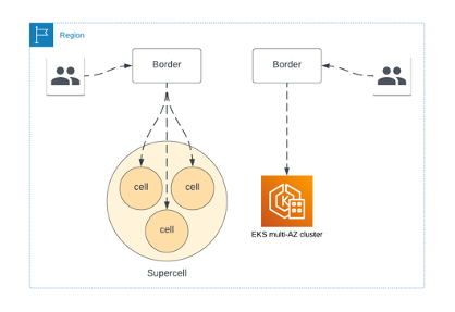
Figure 2: Transition from Amazon EKS multi-AZ to supercell architecture
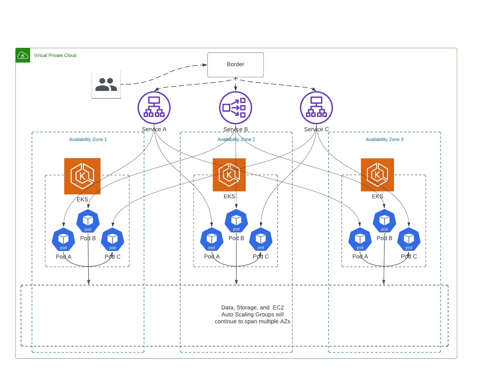
Figure 3: Availability Zone bounded cell-based multi-cluster Amazon EKS
As you can see in the Figure 3, the full stack of services is available in each cell, and once a request is forwarded to a cell it stays in that cell. This reduces our inter-AZ data transfer costs, and provides us AZ failure resiliency since its now relatively simple for us to disable traffic at the Border for the cell that is having an issue. As we roll this out, we’ll initially have both cell-based Amazon EKS clusters and our legacy multi-AZ EKS cluster as shown in Figure 2.
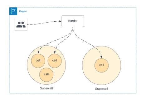
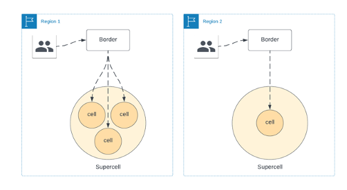
Figure 4: Supercell Architecture
In future, with our supercell architecture, we can have multiple supercells within a single Region as shown in Figure 4. This allows us to route traffic if a cell is down for maintenance, or a slow rollout of a new feature. We’ll continue this model as move into multi-region deployments.
For Kubernetes cluster level autoscaling requirements, we were using cluster autoscaler; however, we ran into limitations when we use multiple Amazon EC2 instance types and sizes. As we were migrating to this cell-based architecture, we identified opportunities for operational improvements to address Amazon EKS scaling using Karpenter and workload management using ArgoCD.
Improved Amazon EKS scaling with Karpenter
For our Amazon EKS workloads, we continue to use horizontal pod autoscaler to scale out our Pods to match demand. For Amazon EKS Cluster autoscaling, we have adopted Karpenter, an open-source, flexible, high-performance Kubernetes cluster autoscaler. Prior to the adoption of Karpenter, we relied on Kubernetes Cluster Autoscaler, which utilizes the concept of node groups as the element of capacity control and scale. In AWS, node groups are implemented by Amazon EC2 Auto Scaling groups. While the cluster autoscaler was functional, there were some inherent limitations of cluster autoscaler that added additional operational work when we want to utilize different types of instance types and sizes. In these scenarios, we have to create multiple node groups, which led to additional operational complexity.
Karpenter has the ability to efficiently address the full range of instance types and capacities available through AWS. With Karpenter, you define Provisioners, made available to Kubernetes as a CRD (Custom Resource Definition). These CRDs are mutable, which gives our operations teams a better user experience when they need to modify our instance types, sizes, and more. It also improves our node utilization by bin packing pending pods on the most efficient Amazon EC2 instance types, resulting in significant cost optimization.
Workload management in Amazon EKS
During the design phase of the project, we identified the need to improve how we manage applications within Amazon EKS. For some time now, we’ve been using a combination of yaml manifests to define Kubernetes resources, and have relied on a combination of Terraform and Jenkins custom pipelines to manage the deployment of resources in our Amazon EKS clusters. The use of Terraform for workload management focused on core infrastructure add-ons like observability applications for log and metric aggregation, controllers to manage AWS resources like Load Balancers and Route53 entries, and other middleware type workloads that are shared by a large portion of Life360 services. The use of Jenkins pipelines with raw yaml was primarily used for Life360 developed services. While both solutions were functional, they weren’t scalable with cell-based design, so we decided to consolidate on a single solution that would allow us to manage our core infrastructure add-ons and our Life360 developed workloads.
We chose ArgoCD to help manage our workloads in Amazon EKS. We wanted our engineers to have an easy-to-use interface to manage their workloads across multiple clusters. This became increasingly more important as we moved from a workload running in a single Amazon EKS cluster, to a workload running in multiple Amazon EKS clusters, each isolated to a single AZ.
There have been a few iterations of our ArgoCD git repository, but we have settled on a solution that’s working extremely well for us now. Our current solution makes heavy use of the ArgoCD ApplicationSet CRD. We now have a custom helm chart that manages the ArgoCD applications that get deployed to a set of clusters that make up the supercell. The chart takes input values similar to the following, and we discuss each in the following code.
We defined the defaults object above to be used by the ApplicationSet chart template. Some values here are passed in as helm global values. This allows us to, for example, use the value global.clusterName if desired in a pod annotation in the custom-app chart template. Next, we have our cluster-cells. We iterate over this object in our chart template to create in support of a list generator. Finally, we have the deployed_applications object. I want to highlight the fields extraHelmParameters and clusterOverrides. Both of these fields allow us to customize the deployed application. This is handled in the ApplicationSet template.
The other fields are used to define the Application configuration that’s generated by the ApplicationSet template. The field name is used in combination with the clusterCell.cluster to generate a unique name for the ArgoCD Application. In this example, ArgoCD would have a total of three Applications generated by the ApplicationSet (i.e., env-use1-az2-custom-app, env-use1-az4-custom-app, and env-use1-az6-custom-app). The fields repoUrl and path are used by the ArgoCD Application to define the source repository and relative path of the helm chart it manages.
Conclusion
In this post, we showed you how we improved our resiliency by implementing a multi-cluster Amazon EKS architecture. Our new approach adopted a bulkhead architecture that used cells to ensure a failure in one cell didn’t affect others. This approach allowed Life360 to reduce inter-AZ data transfer costs, improve EKS scaling and workload management, and create a statically stable infrastructure for AZ-wide failures. With the supercell architecture, Life360 provided uninterrupted service and continued to simplify safety for families globally.

Jesse Gonzalez, Life 360
Jesse Gonzalez (linkedin.com/in/jessegonzalez) is a Senior Staff Engineer at Life360, where he specializes in large-scale infrastructure solutions. He is passionate about guiding the design, implementation, and automation of these solutions, with an emphasis on Kubernetes. Jesse is based out of San Antonio, Texas.

Naveen Puvvula, Life 360
Naveen (linkedin.com/in/pncbose) is a Sr. Engineering Manager at Life360, where he oversees the ilities of its platform – Reliability, Scalability, Availability. Having led successful mobile products earlier in his career, he specializes in client-server interaction layer and Service discovery architecture. He is passionate about building Scalable and Reliable Systems. Naveen is based in Bay Area, California.