Networking & Content Delivery
Preserving client IP address with Proxy protocol v2 and Network Load Balancer
When a load balancer or proxy cannot preserve the client’s original IP address, it may rewrite the IP address or use its own IP address for routing purposes. In this scenario, common practices such as inserting the original IP address into the request headers (for example, X-Forwarded-For) or utilizing Proxy protocol are widely used to ensure that backend services still have access to this information. Application Load Balancers operate at Layer 7 and use the X-Forwarded-For HTTP header to pass the client IP to the target. Network Load Balancers operate at Layer 4, which is the TCP/UDP layer. This is where Proxy protocol comes into play. By encoding essential client details within proxy headers, Proxy protocol enables accurate logging, monitoring, and management of network traffic, enhancing security and visibility in distributed environments.
In this post, you’ll explore how Proxy protocol v2 operates in conjunction with a Network Load Balancer, learn its appropriate use cases, and deploy a CloudFormation template consisting of a Network Load Balancer in front of an NGINX or HAProxy server where Proxy protocol v2 is used to preserve client connection details.
This post focuses on the use of Proxy protocol v2 with TCP connections, though UDP is supported.
How Proxy protocol works
Proxy protocol adds a header at the beginning of a TCP stream. When a client establishes a TCP connection with a server, a three-way handshake is performed, followed by a stream of data. The Proxy protocol v2 header encodes the client connection details and is prepended to the data stream, immediately after the three-way handshake, as depicted in Figure 1. In the case of TLS connections, the Proxy protocol v2 header precedes the TLS handshake.
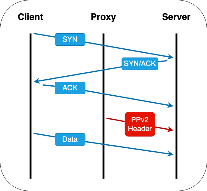
Figure 1: TCP connection flow with Proxy protocol v2 header insertion
Proxy protocol v2 with Network Load Balancer may include the following client connection details:
Source address – The original IP address of the client initiating the connection
Destination address – The IP address of the proxy or load balancer receiving the connection
Source port – The port number on the client side from which the connection originates
Destination port – The port number on the proxy or load balancer side to which the connection is directed
Protocol – The network protocol being used for the connection (for example, TCP or UDP)
Version – The version of the Proxy protocol being used (for example, v2)
Family – The address family of the source and destination IP addresses (for example, IPv4 or IPv6)
Length – The length of the Proxy protocol header
Checksum – A checksum value to ensure the integrity of the header
Type-length-value (TLV) – Custom data (for example, virtual private cloud (VPC) endpoint ID)
These details are encoded in the Proxy protocol v2 header and used by the proxy or load balancer to accurately convey client connection details to the backend server. This enables the backend server to maintain visibility into the original client connection.
Common use cases for Proxy protocol
While Network Load Balancer preserves the client IP address by default, certain considerations may prevent this. For details, refer to our client IP preservation documentation. Preserving the client IP address in the network packets may not be practical or possible in the following use cases. Hence, you use Proxy protocol v2 if your target application needs to know the client connection details.
- Remote targets – Routing to targets outside the VPC of the Network Load Balancer
- PrivateLink – Private connection from service consumer to service provider
- Hairpinning – Client and server are on the same host, most often found in containerized environments
Before you enable Proxy protocol on a target group, make sure that your applications expect and can parse the Proxy protocol v2 header because otherwise they will fail.
1. Remote targets
When employing targets located outside the VPC of a Network Load Balancer, IP targets are necessary, which will automatically deactivate the client IP preservation feature. This scenario is relevant for cross-VPC, hybrid-cloud, and multi-cloud architectures. For instance, Network Load Balancer may be deployed to manage traffic for targets situated on premises, as shown in Figure 2.
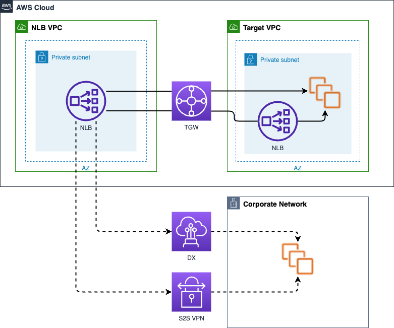
Figure 2: Network Load Balancer routing to remote targets
2. PrivateLink
In the realm of network security and privacy, AWS PrivateLink stands out as a widely used solution for safeguarding internal services while allowing multiple consumers to access them securely. It establishes a unidirectional flow from a VPC endpoint, through the AWS network, to a Network Load Balancer and its targets. Yet, as with any security measure, there are trade-offs. When using PrivateLink, the client connection details are obscured, complicating efforts to trace and manage traffic. With Proxy protocol v2, not only are client IP addresses preserved, but additional context, such as the VPC endpoint ID used by the clients, is encoded within the header. This combination provides insight into the origins of PrivateLink traffic. See Figure 3.
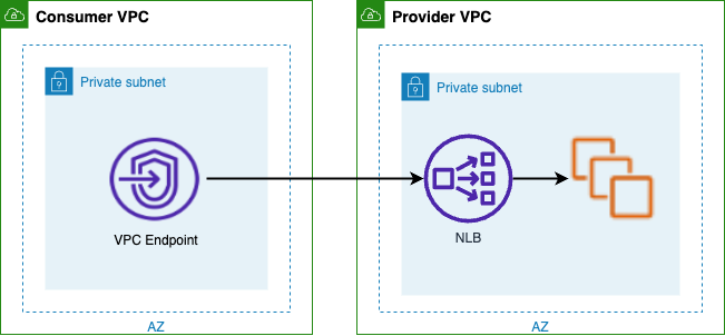
Figure 3: PrivateLink connection
3. Hairpinning
In this context, hairpinning refers to the scenario where traffic originates from and is destined for the same host, passing through a Network Load Balancer, as illustrated in Figure 4. This scenario is most likely to occur in an environment that is running containerized workloads. Connections may fail when hairpinning traffic through a Network Load Balancer due to the way it handles client IP preservation. Deactivating client IP preservation allows for hairpin routing, though it obfuscates the client IP. Use Proxy protocol v2 in this scenario to preserve client connection details.
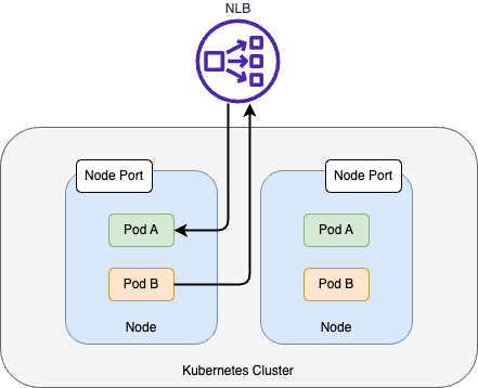
Figure 4: Hairpinning traffic through a Network Load Balancer
Demonstration of Proxy protocol v2
In the upcoming section, we will perform these steps:
- Deploy an AWS CloudFormation template.
- Connect to an Amazon Elastic Compute Cloud (Amazon EC2) web server behind a Network Load Balancer.
- Capture and display network packets containing Proxy protocol v2 headers.
- View EC2 web server access logs.
1. Deploy a CloudFormation template
To get started with a hands-on demonstration, go to the CloudFormation console and use either the NGINX or HAProxy CloudFormation template to deploy a working environment of a Network Load Balancer and target enabled for Proxy protocol v2. Figure 5 illustrates the CloudFormation deployment.
When deploying the template, replace the default value of the ClientCIDR parameter (0.0.0.0/0) with your own IP address. You can view your public IP address by going to the website https://checkip.amazonaws.com. The ClientCIDR parameter is used in a security group to restrict access to the internet-facing Network Load Balancer.
Do not use this CloudFormation template in a production environment. Production Network Load Balancers should be deployed in multiple Availability Zones with logging enabled.
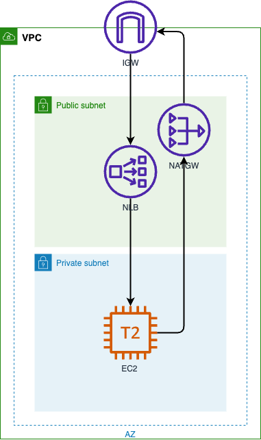
Figure 5: Infrastructure deployed by template
This template sets up all the networking and deploys a simple web application that demonstrates receiving client details from the Proxy protocol v2 headers when traffic is load balanced by a Network Load Balancer.
Some key things the template is doing:
- It is creating a VPC, public and private subnets, an internet gateway, a NAT gateway, and associated routing tables to allow access to the internet from the private subnet.
- An Amazon EC2 security group is defined that will allow ingress on port 80 from the Network Load Balancer.
- An AWS Identity and Access Management (IAM) role and instance profile are created to allow the EC2 instance access to AWS Systems Manager for remote access.
- An EC2 instance is launched in the private subnet with a CloudFormation init configuration that will install and configure NGINX or HAProxy and PHP-FPM. The configuration defines a listener on port 80 that supports Proxy protocol v2 and passes requests to PHP-FPM.
- Index.php displays the client source IP and port found in the Proxy protocol v2 headers passed from the Network Load Balancer. It shows the client and server software used to establish the connection.
2. Connect to an Amazon EC2 web server behind a Network Load Balancer
Deploying the template requires several minutes, followed by additional time for the EC2 instance to undergo health checks and become active. Once operational, use the URL generated by the template (check the Outputs tab of the deployed stack to obtain the URL) to view a web page featuring a table containing client connection details.
When connected, you should see a web page similar to that shown in Figure 6.
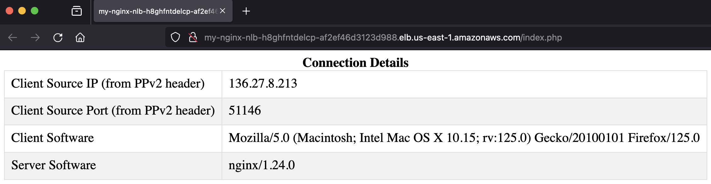
Figure 6: Web page with client details obtained from Proxy protocol v2 header
3. Capture and display network packets containing Proxy protocol v2 headers
Now, we’re going to use a protocol analyzer to capture and display the contents of a Proxy protocol v2 header from the command line of our EC2 instance. Start by using Session Manager, a capability of AWS Systems Manager to connect to the EC2 instance deployed by the CloudFormation template. After connecting, run the tshark command to capture and display Proxy protocol v2 headers, as shown in Figure 7.
sudo tshark --disable-protocol http -VY proxy.v2.protocol==0x01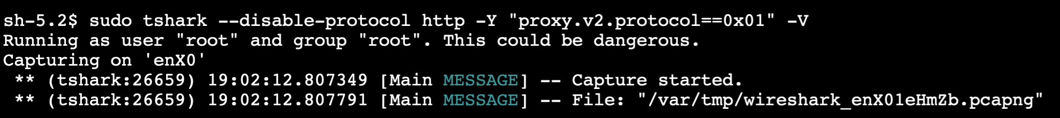
Figure 7: Using tshark to capture and display network packets containing Proxy protocol v2 headers
Once the protocol analyzer is running, open up a web browser or any HTTP-compatible client on your workstation and point it at the URL provided by the template. For example, you may choose to use cURL, as shown in the following code snippet, replacing the URL with the one provided by the template.
curl <http://replace-me.elb.region.amazonaws.com/index.php>On your EC2 instance, the protocol analyzer should capture and display the contents of the network packet containing the Proxy protocol v2 header. See Figure 8 for an example. The output is truncated for brevity.
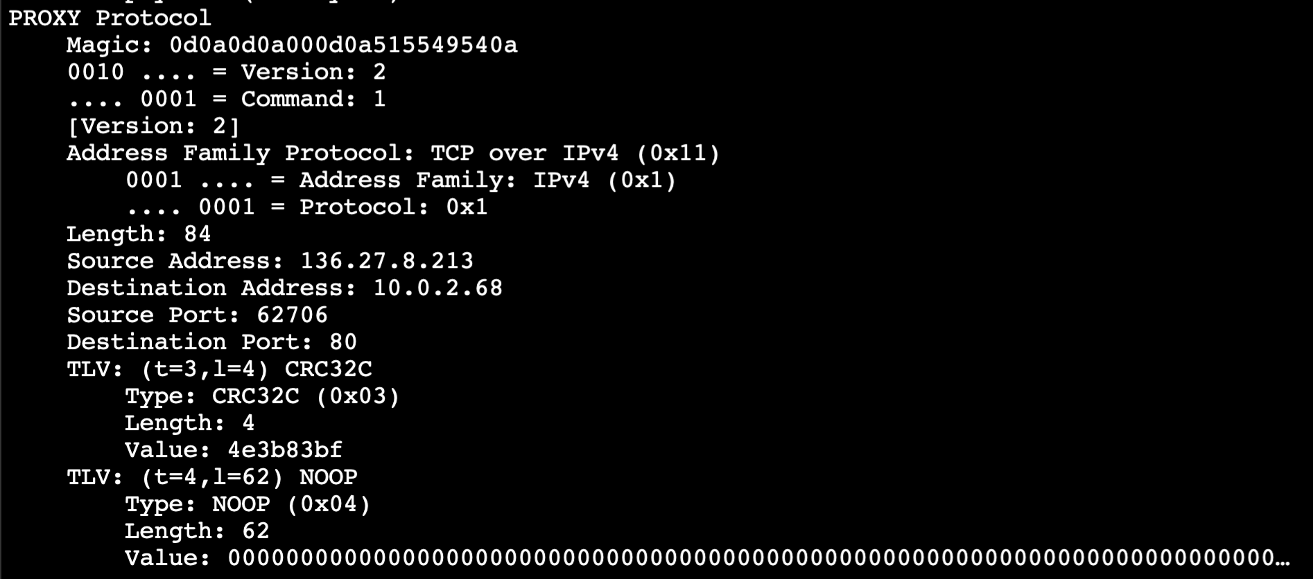
Figure 8: Screenshot of decoded Proxy protocol v2 header
4. View EC2 web server access logs
Finally, you’ll look at the access log of the web server, which has been configured to log client IP addresses discovered in Proxy protocol v2 headers. From the command line of the web server, run the command shown in Figures 9 or 10. Log entries that do not contain an IP address or that contain the IP address of your Network Load Balancer are health checks, which probe the server periodically but do not provide any client connection details.
Once you are viewing the access log, generate fresh log entries by connecting to the URL from your workstation. Notice that the source IP address that gets recorded in the access log is the one found in the Proxy protocol v2 header.
The command shown in Figures 9 and 10 will output log entries in real time using elevated privileges. Be sure to use the correct log file location based on the CloudFormation template you deployed.
If you deployed NGINX, use the following command (output shown in Figure 9):
sudo tail -f /var/log/nginx/access.log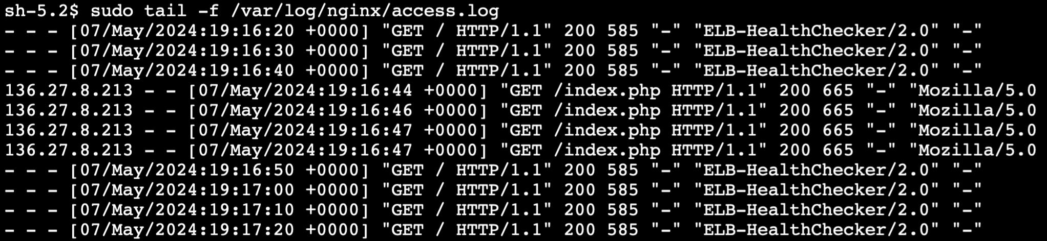
Figure 9: Screenshot of NGINX access log
If you deployed HAProxy, use the following command (output shown in Figure 10):
sudo tail -f /var/log/haproxy/access.log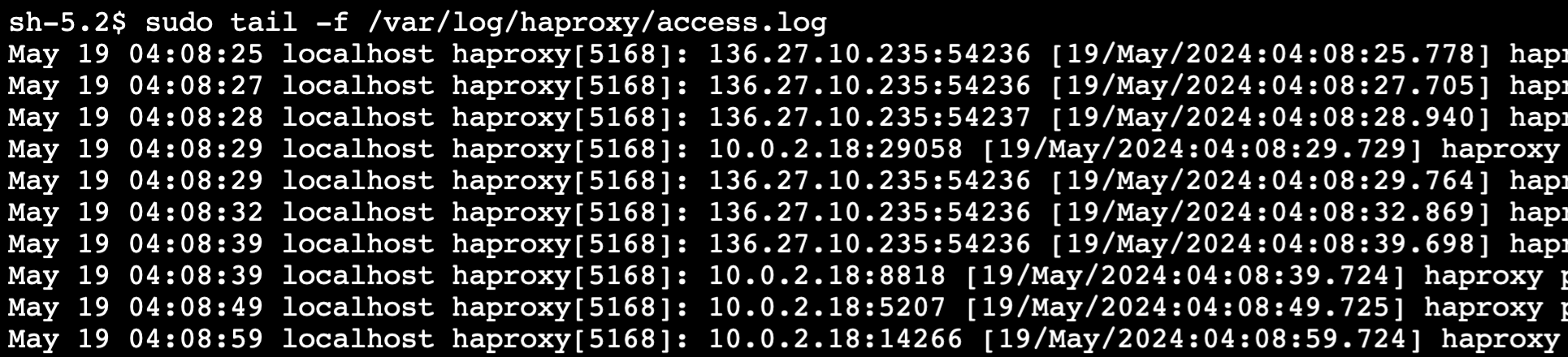
Figure 10: Screenshot of HAproxy access log
This concludes the hands-on demonstration. Though this post focused on the use of NGINX and HAProxy as targets of a Network Load Balancer, the concepts are applicable to similar platforms such as Envoy, Traefik, and others. Most enterprise-grade proxies and web servers support Proxy protocol v2, though some may not.
Cleanup
Delete the CloudFormation stack once you finish to avoid unnecessary charges.
Conclusion
Network Load Balancer and Proxy protocol v2 serve as a protocol-agnostic way to overcome the challenges associated with preserving client connection details when using proxies and load balancers. By encoding client details within proxy headers, Proxy protocol v2 enables accurate logging, monitoring, and management of network traffic, enhancing security and visibility in distributed environments.
In this post, we delved into the inner workings of Proxy protocol v2, explored common use cases, and got hands on using a CloudFormation template. Armed with this knowledge and hands-on experience, you’ll feel more confident enabling Proxy protocol v2 on your Network Load Balancers.
About the author

Ken Kitts
Ken Kitts is a Technical Account Manager at AWS, bringing over two decades of experience in computer networking to the role. Before joining AWS, he specialized in software-defined networking for a fintech. Ken has a passion for travel and archaeology, often visiting local museums and archaeological sites during his travels. His favorite site is Teotihuacan in Mexico.