Containers
How to use Multiple load balancer Target Group Support for Amazon ECS to access internal and external service endpoint using the same DNS name
Customers running container-based applications on Amazon ECS using Amazon EC2 (commonly referred to as EC2) or AWS Fargate, frequently need to expose the application to both external clients and internal clients within the Amazon VPC (commonly referred to as VPC). In this blog post, we will look at a solution to optimize cost and reduce operational complexity of such an architecture by utilizing a new Amazon ECS feature launched on July 30th 2019 and an existing Route 53 feature.
The new feature of Multiple Load Balancer Target Group support for Amazon ECS allows you to attach a single Amazon ECS service running on either EC2 or AWS Fargate, to multiple target groups. We will also use a well-known feature of Route 53 that will let us map a Fully Qualified Domain Name (FQDN) to public IP address for clients accessing from internet and to private IP address for clients accessing from within the VPC.
Before I explain the solution, let’s look at how this has traditionally been achieved using two different approaches and its limitations.
- By letting both internal and external traffic towards the service, traverse the Internet Gateway before reaching the internet facing Application Load Balancer (ALB). The service is hosted behind this load balancer, as shown in the diagram below. While this setup is simple, it adds to the latency and data transfer costs.
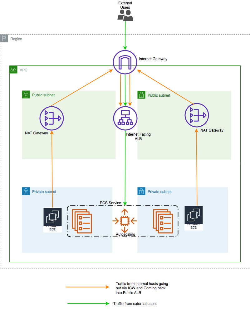 Figure 1:Using public endpoint for both internal and external traffic.
2. By deploying two copies of the same service, one behind an internet facing public ALB for external users and one behind an internal ALB for internal consumption from within the VPC as shown in the below figure. Figure2: Using two copies of the same service
As mentioned above both methods incur additional costs and operational burden.
Architecture:
This section describes the steps to implement the architecture:
- Deploy a simple web server running on AWS Fargate within a private subnet.
- Add it to a Target Group.
- Associate the Target Group to an internet facing load balancer.
- Create an internal load balancer.
- Add the same AWS Fargate service in a Target Group associated with this internal load balancer.
As shown in the diagram below, first step will be to create a VPC with two private subnets and two public subnets. To enable the AWS Fargate tasks to download Docker images from Amazon ECR, we will deploy two Network Address Translation (NAT) gateways in the public subnets. In addition to that, we will also deploy a Bastion Host in the public subnet. This will be provisioned using an AWS CloudFormation template (provided later in this post).

Figure 3: Using new Amazon ECS feature
Prerequisites:
- AWS Command Line Interface (AWS CLI): You need AWS CLI installed and configured on the workstation from where you are going to try the steps mentioned below.
- Credentials configured in AWS CLI should have the required IAM permissions to spin up and modify the resources mentioned in this post.
- Make sure that you deploy the solution to us-east-1 Region and your AWS CLI default Region is us-east-1. If us-east-1 is not the default Region, please mentioned the Regions explicitly while executing AWS CLI commands using
--region us-east-1switch.
Implementation:
- Generate and Save Keys for EC2 instances.
- Create a Key Pair
aws ec2 create-key-pair \ --key-name MyKeyPair \ --query 'KeyMaterial' \ --output text > MyKeyPair.pem - Change permission of the private key pair file.
chmod 400 MyKeyPair.pem - If you are using Windows workstation, then follow the steps mentioned here to convert the private key to ppk format.
- Create a Key Pair
- Download and unzip CloudFormation script and config files to be used in this blog from this link. You will have to run all AWS CLI commands from the folder where these files are present. Below are the details of these files.
vpc-stack-for-ecs-multi-target.yml: CloudFormation script to create VPC and related resources.fargate-task.json: ECS task definition.fargate-service.json: ECS service definition.change-record-set-public.json: DNS change record set for public zone.change-record-set-private.json: DNS change record set for private zone.
- Create the VPC with public and private subnets along with NAT Gateways and Bastion Host in it by executing the AWS CloudFormation template mentioned in steps below:
- Deploy CloudFormation stack using CLI by executing the command below. Replace stack
name with a name of your choice. Also replace the value of key “BastionHostSSHKey” with
the key pair created in step 1. You can change other default parameter values highlighted
below, by assigning desired values to respective keys.aws cloudformation create-stack --stack-name mystack --template-body \ file://vpc-stack-for-ecs-multi-target.yml --parameters \ ParameterKey=VPCCIDR,ParameterValue=10.100.0.0/16 \ ParameterKey=PublicSubnet1,ParameterValue=10.100.0.0/24 \ ParameterKey=PublicSubnet2,ParameterValue=10.100.1.0/24 \ ParameterKey=PrivateSubnet1,ParameterValue=10.100.2.0/24 \ ParameterKey=PrivateSubnet2,ParameterValue=10.100.3.0/24 \ ParameterKey=BastionHostAMIid,ParameterValue=ami-009d6802948d06e52 \ ParameterKey=BastionHostSSHKey,ParameterValue=MyKeyPair \ ParameterKey=TagPrefix,ParameterValue=mystackOutput of the command will be a stack id as shown below:
{ "StackId": "arn:aws:cloudformation:us-east-1: 123456781234:stack/mystack1/59fb3560-0394-11ea-96e7-12ccfe651680" } - Stack creation will take approximately 7 minutes. Check the status of the stack by executing the below command every few minutes. You should see
StackStatusvalue asCREATE_COMPLETE.aws cloudformation describe-stacks --stack-name <name of your stack from above step> | grep StackStatusExample:
aws cloudformation describe-stacks --stack-name mystack | grep StackStatus
Output:
"StackStatus": "CREATE_COMPLETE",
- Once the stack status changes to
"CREATE_COMPLETE", use the below command to store the Logical IDs and corresponding Physical IDs for all resources in a file on your local disk. We will be using these IDs throughout this blog post.aws cloudformation list-stack-resources --stack-name mystack > stackresources.jsonThe file created in this step will have content similar to the one shown in the snippet below:
{
"StackResourceSummaries": [
{
"ResourceStatus": "CREATE_COMPLETE",
"DriftInformation": {
"StackResourceDriftStatus": "NOT_CHECKED"
},
"ResourceType": "AWS::EC2::SecurityGroup",
"LastUpdatedTimestamp": "2019-11-10T08:18:10.698Z",
"PhysicalResourceId": "sg-0ea6deae91d12fa6b","LogicalResourceId": "BastionHostSG"
},
{
"ResourceStatus": "CREATE_COMPLETE",
"DriftInformation": {
"StackResourceDriftStatus": "NOT_CHECKED"
},
"ResourceType": "AWS::EC2::Instance",
"LastUpdatedTimestamp": "2019-11-10T08:18:57.370Z",
"PhysicalResourceId": "i-05e716b660f487f28","LogicalResourceId": "EC2Instance"
},
{
"ResourceStatus": "CREATE_COMPLETE",
"DriftInformation": {
"StackResourceDriftStatus": "NOT_CHECKED"
},
"ResourceType": "AWS::EC2::VPCGatewayAttachment",
"LastUpdatedTimestamp": "2019-11-10T08:18:20.319Z",
"PhysicalResourceId": "mysta-Gatew-70P2BNQRAD5D","LogicalResourceId": "GatewayToInternet"
},
<snip>
If you do not want to use CLI for this step, you can create the stack from AWS web console by following the steps mentioned below:
- Log in to AWS web console.
- Select/Click CloudFormation and then click on Create Stack.
- In Select Template screen, click on ‘Upload a template to Amazon S3’ then ‘Browse’ button and then select the template downloaded in above step and click on ‘Next’.
- In the resulting screen type in a ‘Stack name’, select the SSH key file you downloaded in step 1. You can change the other default values to a desired value, like VPC CIDR, subnets etc. and then click on ‘Next.’
- Click ‘Next’ again and on resulting screen click on ‘Create.’
- Once the stack status changes to “CREATE_COMPLETE,” navigate to the “Resources” tab and note the Logical IDs and corresponding Physical IDs for all resources. We will be using them throughout this blog post.
- Deploy CloudFormation stack using CLI by executing the command below. Replace stack
- Create an internet facing Application Load Balancer with corresponding Target Group and Listener in public subnet of the VPC you created in step 3.
- Create internet facing Application Load Balancer from AWS CLI:
aws elbv2 create-load-balancer --name my-public-load-balancer \
--subnets < PubSubnet1_physical-id> <PubSubnet2_physical-id > \
--security-groups < PublicALBSG_physical-id> \
--scheme internet-facing
From the output of this command, note the values of LoadBalancerArn and DNSName.
Example:
aws elbv2 create-load-balancer --name my-public-load-balancer \
--subnets subnet-0d60f4ddf054a141f subnet-0918256af62ca087c \
--security-groups sg-08484bf60eec152e9 --scheme internet-facing
Output:
Output:
{
"LoadBalancers": [
{
"IpAddressType": "ipv4",
"VpcId": "vpc-0d8f13587581059a7",
"LoadBalancerArn": "arn:aws:elasticloadbalancing:us-east-1:123456781234:loadbalancer/app/my-public-load-balancer/0d4d265cac24026a",
"State": {
"Code": "provisioning"
},
"DNSName": "my-public-load-balancer-16835954.us-east-1.elb.amazonaws.com",
"SecurityGroups": [
"sg-08484bf60eec152e9"
],
"LoadBalancerName": "my-public-load-balancer",
"CreatedTime": "2019-08-18T15:04:01.290Z",
"Scheme": "internet-facing",
"Type": "application",
"CanonicalHostedZoneId": "Z35SXDOTRQ7X7K",
"AvailabilityZones": [
{
"SubnetId": "subnet-0918256af62ca087c",
"ZoneName": "us-east-1a"
},
{
"SubnetId": "subnet-0d60f4ddf054a141f",
"ZoneName": "us-east-1b"
}
]
}
]
}
- Create Target Group to be placed behind this public ALB from AWS CLI.
aws elbv2 create-target-group --name <NameOfTargetGroup> \
--protocol HTTP --port 80 \
--vpc-id <VPC_physical_id> --target-type ip
From the output of this command, note the values of TargetGroupArn.
Example:
aws elbv2 create-target-group --name my-public-targets-ip \
--protocol HTTP --port 80 \
--vpc-id vpc-0d8f13587581059a7 --target-type ip
Output:
{
"TargetGroups": [
{
"HealthCheckPath": "/",
"HealthCheckIntervalSeconds": 30,
"VpcId": "vpc-0d8f13587581059a7",
"Protocol": "HTTP",
"HealthCheckTimeoutSeconds": 5,
"TargetType": "ip",
"HealthCheckProtocol": "HTTP",
"UnhealthyThresholdCount": 2,
"HealthyThresholdCount": 5,
"TargetGroupArn":"arn:aws:elasticloadbalancing:us-east-1:123456781234:targetgroup/my-public-targets-ip/346bf000f7740a79",
"Matcher": {
"HttpCode": "200"
},
"HealthCheckPort": "traffic-port",
"Port": 80,
"TargetGroupName": "my-public-targets-ip"
}
]
}
- Create a listener for the Public ALB using AWS CLI.
aws elbv2 create-listener --load-balancer-arn <LoadBalancerArnValue> \
--protocol HTTP --port 80 \
--default-actions Type=forward,TargetGroupArn=< TargetGroupArn Value>
From the output of this command, note the values of ListenerArn.
Example:
aws elbv2 create-listener --load-balancer-arn
arn:aws:elasticloadbalancing:us-east-1:123456781234:loadbalancer/app/my-public-loadbalancer/0d4d265cac24026a \
--protocol HTTP --port 80 \
--default-actions Type=forward,TargetGroupArn=arn:aws:elasticloadbalancing:us-east-1:123456781234:targetgroup/my-public-targets-ip/346bf000f7740a79
Output:
{
"Listeners": [
{
"Protocol": "HTTP",
"DefaultActions": [
{
"TargetGroupArn":
"arn:aws:elasticloadbalancing:us-east-1:123456781234:targetgroup/my-public-targets-ip/346bf000f7740a79",
"Type": "forward"
}
],
"LoadBalancerArn": "arn:aws:elasticloadbalancing:us-east-
1: 123456781234:loadbalancer/app/my-public-load-
balancer/0d4d265cac24026a",
"Port": 80,
"ListenerArn": "arn:aws:elasticloadbalancing:us-east-1:123456781234:listener/app/my-public-load-balancer/0d4d265cac24026a/40aac6603733555c"
}
]
}
- Create internet facing Application Load Balancer from AWS CLI:
- Create an Internal Application Load Balancer with corresponding Target Group and Listener in private subnets of the VPC you created in step 3.
- Create internal Application Load Balancer from AWS CLI.
aws elbv2 create-load-balancer --name my-private-load-balancer \
--subnets <PriSubnet1_physical-id> <PriSubnet2_physical-id> \
--security-groups <PrivateALBSG_physical-id> \
--scheme internal
From the output of this command note the values of LoadBalancerArn and DNSName.
Example:
aws elbv2 create-load-balancer --name my-private-load-balancer \
--subnets subnet-0080a41458f06e427 subnet-0bf169aed3cae352b \
--security-groups sg-0ec02727d55db7e1d \
--scheme internal
Output:
{
"LoadBalancers": [
{
"IpAddressType": "ipv4",
"VpcId": "vpc-0d8f13587581059a7",
"LoadBalancerArn": "arn:aws:elasticloadbalancing:us-east-1:123456781234:loadbalancer/app/my-private-load- balancer/8e8e37258850dba5",
"State": {
"Code": "provisioning"
},
"DNSName": "internal-my-private-load-balancer-1367652196.us-east-1.elb.amazonaws.com",
"SecurityGroups": [
"sg-0ec02727d55db7e1d"
],
"LoadBalancerName": "my-private-load-balancer",
"CreatedTime": "2019-08-18T15:07:22.600Z",
"Scheme": "internal",
"Type": "application",
"CanonicalHostedZoneId": "Z35SXDOTRQ7X7K",
"AvailabilityZones": [
{
"SubnetId": "subnet-0080a41458f06e427",
"ZoneName": "us-east-1a"
},
{
"SubnetId": "subnet-0bf169aed3cae352b",
"ZoneName": "us-east-1b"
}
]
}
]
}
- Create Target Group to be placed behind this internal ALB from AWS CLI.
aws elbv2 create-target-group --name <NameOfTargetGroup> \
--protocol HTTP --port 80 \
--vpc-id <VPC_physical_id> \
--target-type ip
From the output of this command note the values of TargetGroupArn.
Example:
aws elbv2 create-target-group --name my-private-targets-ip \
--protocol HTTP --port 80 \
--vpc-id vpc-0d8f13587581059a7 \
--target-type ip
Output:
{
"TargetGroups": [
{
"HealthCheckPath": "/",
"HealthCheckIntervalSeconds": 30,
"VpcId": "vpc-0d8f13587581059a7",
"Protocol": "HTTP",
"HealthCheckTimeoutSeconds": 5,
"TargetType": "ip",
"HealthCheckProtocol": "HTTP",
"UnhealthyThresholdCount": 2,
"HealthyThresholdCount": 5,
"TargetGroupArn": "arn:aws:elasticloadbalancing:us-east-1:123456781234:targetgroup/my-private-targets-ip/0bd8ac40c4cc88b0",
"Matcher": {
"HttpCode": "200"
},
"HealthCheckPort": "traffic-port",
"Port": 80,
"TargetGroupName": "my-private-targets-ip"
}
]
}
- Create a listener for the Internal ALB using AWS CLI.
aws elbv2 create-listener --load-balancer-arn < LoadBalancerArn Value> \
--protocol HTTP --port 80 \
--default-actions Type=forward,TargetGroupArn=< TargetGroupArn Value>
From the output of this command, note the values of ListenerArn.
Example:
aws elbv2 create-listener --load-balancer-arn arn:aws:elasticloadbalancing:us-east-1:123456781234:loadbalancer/app/my-private-load-balancer/8e8e37258850dba5 \
--protocol HTTP --port 80 \
--default-actions Type=forward,TargetGroupArn=arn:aws:elasticloadbalancing:us-east-1:123456781234:targetgroup/my-private-targets-ip/0bd8ac40c4cc88b0
Output:
{
"Listeners": [
{
"Protocol": "HTTP",
"DefaultActions": [
{
"TargetGroupArn":
"arn:aws:elasticloadbalancing:us-east-1:123456781234:targetgroup/my-private-targets-ip/0bd8ac40c4cc88b0","Type": "forward"
}
],
"LoadBalancerArn": "arn:aws:elasticloadbalancing:us-east-1:123456781234:loadbalancer/app/my-private-load-balancer/8e8e37258850dba5",
"Port": 80,
"ListenerArn": "arn:aws:elasticloadbalancing:us-east-1:123456781234:listener/app/my-private-load-balancer/8e8e37258850dba5/3dd5e949709a37d9"
}
]
}
- Create internal Application Load Balancer from AWS CLI.
Now that we have basic infrastructure in place, let’s start setting up ECS service. In this section we will:
- Create an Amazon ECS cluster.
- Register a task definition.
- Create a service using this task definition and make it part of two different target groups associated to two different load balancers, as mentioned in the beginning of this post.
- Create an Amazon ECS cluster from AWS CLI by executing the below command.
aws ecs create-cluster --cluster-name fargate-cluster - Register the task definition. Use
fargate-task.jsontask definition JSON file downloaded in step 2. Then run the following command in AWS CLI.aws ecs register-task-definition --cli-input-json file://fargate-task.json - Deploy a service under Amazon ECS cluster created in step 6 using the task definition registered in step 7. For that, use the service definition JSON file
fargate-service.jsondownloaded in setp 2 and modify the following in your favorite editor before executing the command.- Replace the subnets under “subnets” with the physical-id of PriSubnet1 and PriSubnet2 from CloudFormation output section.
- Replace value for “securityGroups” value with the physical-id of PrivateALBSG.
- Replace the value of first “targetGroupArn” under “loadBalancers” with the value of
TargetGroupArnyou recorded in step 4 for internet facing ALB. Also replace the value of second “targetGroupArn” under “loadBalancers” with the value ofTargetGroupArnyou recorded in step 5 for internal ALB.
Once done, execute the command below:
aws ecs create-service --cluster <cluster-name>  --service-name <service-name>  \
--cli-input-json file://fargate-service.json
Example:
aws ecs create-service --cluster fargate-cluster --service-name fargate-service \
--cli-input-json file://fargate-service.json
At this point we will have the Fargate service created above, running behind internet facing ALB and Internal ALB. To verify if the service is functioning as desired, SSH into the bastion host and find out if the internal load balancer is resolving to a private IP address and is servicing the content hosted by the service.
nslookup internal-my-private-load-balancer-1367652196.us-east-1.elb.amazonaws.comOutput:
Server:10.100.0.2

 Address:10.100.0.2#53


 Non-authoritative answer:


 Name: internal-my-private-load-balancer-1367652196.us-east-1.elb.amazonaws.com


 Address: 10.100.2.81


 Name: internal-my-private-load-balancer-1367652196.us-east-1.elb.amazonaws.com


 Address:
         10.100.3.88
It’s resolving to private IP addresses. Now let’s check if its serving the content.
curl http://my-public-load-balancer-16835954.us-east-1.elb.amazonaws.com
Output:
<html> <head> <title>Amazon ECS Sample App</title> <style>body {margin-top: 40px; background-color: #333;} </style> </head><body> <div style=color:white;text- align:center> <h1>Amazon ECS Sample App</h1> <h2>Congratulations!</h2> <p>Your application is now running on a container in Amazon ECS.</p> </div></body></html>And yes, it’s accessible and serving the content!
Now from any workstation with internet access, let’s try to resolve the internet facing ALB endpoint and check for content, as shown below.
nslookup my-public-load-balancer-16835954.us-east-1.elb.amazonaws.comOutput:
Server:10.4.4.10

 Address:10.4.4.10#53


 Non-authoritative answer:


 Name: my-public-load-balancer-16835954.us-east-1.elb.amazonaws.com


 Address: 52.207.100.199


 Name: my-public-load-balancer-16835954.us-east-1.elb.amazonaws.com


 Address: 52.1.126.139
curl http://my-public-load-balancer-16835954.us-east-1.elb.amazonaws.com
Output:
<html> <head> <title>Amazon ECS Sample App</title> <style>body {margin-top: 40px; background-color: #333;} </style> </head><body> <div style=color:white;text- align:center> <h1>Amazon ECS Sample App</h1> <h2>Congratulations!</h2> <p>Your application is now running on a container in Amazon ECS.</p> </div></body></html>Awesome! It’s resolving to a public IP address and is accessible from internet and is serving the same content.
Now that we have verified that same service behind two different ALBs (one internal and one internet facing) is accessible internally and from internet, let’s move on to next section where we will configure Route 53 to resolve a domain name to private IP address from within the VPC and to a public IP address when resolved from the internet.
DNS Configuration:
You can use Route 53 to configure split-view DNS, also known as split-horizon DNS. This feature can be used when you want to maintain internal and external versions of the same website, application, or service.
You can maintain both a private and public hosted zone with the same domain name for split-view DNS with Amazon Route 53. The following instructions assume you already own a domain and have the rights to make changes to the NS records for that domain. Amazon Route 53 private hosted zones require DNS queries to be sourced from the VPC DNS server rather than a custom DNS server.
- Ensure that DNS resolution and DNS hostnames are enabled on the source VPC.
Note: DNS hostnames are enabled for default VPCs and VPCs that you create using the VPC wizard in the VPC console. - Create a public hosted zone that matches the name of the domain you purchased. Skip this step if you already have a public hosted zone that you want to use. I am going to use awsdemodesign.com.
aws route53 create-hosted-zone --name awsdemodesign.com \ --caller-reference 2018-08-22-20:15 \ --hosted-zone-config Comment="Public Hosted Zone Demo DNS" - Verify the details of newly created hosted zone by listing it and record the Id. See below for example. Skip this step if you already have a public hosted zone that you want to use.
aws route53 list-hosted-zonesOutput:
{
 "HostedZones": [


 {


 "ResourceRecordSetCount": 2,


 "CallerReference": "747650B5-BA21-226C-BDCD-46815EAFEB00",


 "Config": {


 "Comment": "Public Hosted Zone Demo DNS",


 "PrivateZone": false


 },


 "Id": "/hostedzone/Z137GDD2RSPII7",


 "Name": "awsdemodesign.com."


 }


 ]


} - Populate the public hosted zone with the required records. If you are using DNS provider other than Route 53, then make this change in your current public DNS. We will be pointing ecs-mtg-demo1.awsdemodesign.com to internet facing ALB endpoint via a CNAME. To do this from AWS CLI the change record set needs to be in JSON format and ‘hosted-zone-id’ value should be the one captured from above step, as shown below followed by the actual command. You can use the change record set sample JSON file
change-record-set-public.jsondownloaded at the begining of this blog or create the change-record-set-public.json file using the content shown below.
{
"Changes": [
{
"Action": "CREATE",
"ResourceRecordSet": {
"Name": "ecs-mtg-demo1.awsdemodesign.com",
"Type": "CNAME",
"TTL": 3600,
"ResourceRecords": [[{"Value": "my-public-load-balancer-16835954.us-east-1.elb.amazonaws.com}]]
}
}
]
}
AWS CLI Command:
 aws route53 change-resource-record-sets \
--hosted-zone-id Z137GDD2RSPII7 \
--change-batch file://change-record-set-public.json
Output:
{ "ChangeInfo": { "Status": "PENDING", "SubmittedAt": "2019-08-22T15:41:07.940Z", "Id": "/change/CZAT02J60RVJC" } } - Update your registrar’s NS records with the name servers provided in your public hosted zone.
- Create a private hosted zone that matches the name of the public hosted zone. Attach the private hosted zone to the VPC (created in the beginning of the post) where you want to resolve the domain internally. I am going to use awsdemodesign.com using AWS CLI, same as my public hosted zone and then record the zone id, as shown below.
Note: The private zone lookup will take place within the VPC.Command:aws route53 create-hosted-zone \ --name awsdemodesign.com \ --caller-reference 2018-08-22-22:30 \ --vpc VPCRegion=us-east-1,VPCId=vpc 0d8f13587581059a7 \ --hosted-zone-config Comment="Private Hosted Zone Demo DNS",PrivateZone=TrueOutput:
{
"ChangeInfo": {
"Status": "PENDING",
"SubmittedAt": "2019-08-22T16:03:36.296Z",
"Id": "/change/C2UT5GCE1X5ZZO"
},
"HostedZone": {
"ResourceRecordSetCount": 2,
"CallerReference": "2018-08-22-22:30",
"Config": {
"Comment": "Private Hosted Zone Demo DNS",
"PrivateZone": true
},
"Id": "/hostedzone/ZY0V8EZSBYEWL",
"Name": "awsdemodesign.com."
},
"Location": "https://route53.amazonaws.com/2013-04-01/hostedzone/ZY0V8EZSBYEWL",
"VPC": {
"VPCId": "vpc-0d8f13587581059a7",
"VPCRegion": "us-east-1"
}
}
- Populate the private hosted zone with the required records. I will be pointing ecs-mtg-demo1.awsdemodesign.com to Internal ALB endpoint via a CNAME. To do it from AWS CLI the change record set needs to be in JSON format and ‘hosted-zone-id’ value should be the one captured from above step, as shown below followed by the actual command. You can use the change record set sample JSON file
change-record-set-private.jsondownloaded at the begining of this blog or create the change-record-set-private.json file using the content shown below.
{
"Changes": [
{
"Action": "CREATE",
"ResourceRecordSet": {
"Name": "ecs-mtg-demo1.awsdemodesign.com",
"Type": "CNAME",
"TTL": 3600,
"ResourceRecords": [ {"Value": " internal-my-private-load-balancer-1367652196.us-east-1.elb.amazonaws.com"}]
}
}
]
}
AWS CLI Command:
aws route53 change-resource-record-sets \
--hosted-zone-id ZY0V8EZSBYEWL \
--change-batch file://change-record-set-private.json
Output:
{
"ChangeInfo": {
"Status": "PENDING",
"SubmittedAt": "2019-08-22T16:12:25.869Z",
"Id": "/change/C2D0H2FZJ1CYBZ"
}
}
Note: The public zone will not be queried if a record exists in the private zone.
DNS queries will respond with answers based on the source of the request. From within the VPC, queries for ecs-mtg-demo1.awsdemodesign.com will resolve to internal ALB and queries for ecs-mtg-demo1.awsdemodesign.com from internet will return answers from the public hosted zone and resolve to internet facing ALB. Let’s verify that.
To verify, SSH into the bastion host and find out if the ecs-mtg-demo1.awsdemodesign.com is resolving to private IP addresses of internal ALB and is servicing the content hosted by the service.
nslookup ecs-mtg-demo1.awsdemodesign.com
Output:
Server:10.100.0.2 Address:10.100.0.2#53 Non-authoritative answer: ecs-mtg-demo1.awsdemodesign.com canonical name = internal-my-private-load-balancer-1367652196.us-east-1.elb.amazonaws.com. Name: internal-my-private-load-balancer-1367652196.us-east-1.elb.amazonaws.com Address: 10.100.2.81 Name: internal-my-private-load-balancer-1367652196.us-east-1.elb.amazonaws.com Address: 10.100.3.88It’s resolving to private IP addresses. Now let’s check if it is serving the content.
curl http://ecs-mtg-demo1.awsdemodesign.com
Output:
<html> <head> <title>Amazon ECS Sample App</title> <style>body {margin-top: 40px; background-color: #333;} </style> </head><body> <div style=color:white;text- align:center> <h1>Amazon ECS Sample App</h1> <h2>Congratulations!</h2> <p>Your application is now running on a container in Amazon ECS.</p> </div></body></html>And yes, it’s accessible and serving the content!
Now from a workstation outside the VPC, with internet access, let’s try to resolve the same hostname of ecs-mtg-demo1.awsdemodesign.com and check for content, as shown below.
nslookup ecs-mtg-demo1.awsdemodesign.comOutput
Server:10.4.4.10 Address:10.4.4.10#53 Non-authoritative answer: ecs-mtg-demo1.awsdemodesign.com canonical name = my-public-load-balancer-16835954.us-east-1.elb.amazonaws.com. Name: my-public-load-balancer-16835954.us-east-1.elb.amazonaws.com Address: 52.207.100.199 Name: my-public-load-balancer-16835954.us-east-1.elb.amazonaws.com Address: 52.1.126.139It’s resolving to public IP addresses. Now let’s check if it is serving the content.
curl http://ecs-mtg-demo1.awsdemodesign.comOutput:
<html> <head> <title>Amazon ECS Sample App</title> <style>body {margin-top: 40px; background-color: #333;} </style> </head><body> <div style=color:white;text- align:center> <h1>Amazon ECS Sample App</h1> <h2>Congratulations!</h2> <p>Your application is now running on a container in Amazon ECS.</p> </div></body></html>Awesome! It’s working as per the architecture.
Conclusion
Using Amazon ECS services’ support for multiple load balancer target groups and Route 53’s Split Horizon feature, you can access the Amazon ECS service using the same Fully Qualified Hostname from internet as well as from within the VPC. This will optimize cost and reduce operational complexity of running such services in Amazon ECS.