Containers
Exploring the effect of Topology Aware Hints on network traffic in Amazon Elastic Kubernetes Service
Note: Topology Aware Hints has been renamed to Topology Aware Routing on Kubernetes 1.27. At the time of writing, we used Topology Aware Hints as the name of this function.
Introduction
A best practice for architecting resilient systems in AWS is to leverage multiple Availability Zones (AZs). AWS Regions are composed of multiple AZs designed to be independent of each other and are separate by a meaningful physical distance to avoid correlated failure scenarios. Amazon Elastic Kubernetes Service (Amazon EKS). This functionality makes it possible for customers to run their mission-critical workloads across multiple distinct AZs, providing increased availability by combining Amazon’s global infrastructure with Kubernetes constructs such as pod topology spread constraints.
However, when architecting workloads in this manner there are considerations in terms of both latency and cost to consider. Pods within the same Amazon EKS cluster can easily communicate using a Kubernetes Cluster IP Service, which routes traffic to its associated pods even if they are in different AZs. Although this is a convenient way to take advantage of multiple AZs, some customers may want to bias traffic routing to pods in the same AZ as the originator. Keeping traffic in the same AZ benefits latency sensitive workloads for low latency, and can reduce inter-AZ data transfer costs.
Topology Aware Hints (TAH) is a feature that reached beta status in Kubernetes version 1.23 and became available in Amazon EKS version 1.24. It’s intended to provide a mechanism that attempts to keep traffic closer to its origin within the same AZ on in another location. In this post, we’ll explore how this feature can be used with Amazon EKS, its effects on how traffic is routed between pods within an Amazon EKS cluster when using multiple AZs, and whether this functionality allows Amazon EKS customers to optimize the latency and inter-AZ data transfer costs in this architecture.
Solution overview
How TAH work
How a Kubernetes Service works
Before we introduce how TAH works, let’s introduce how a Kubernetes Service works. When you create a Service you specify a selector to target specific pods. Kubernetes creates an Endpoints object, which it keeps populated with the IP addresses of the relevant pods.
Next, the Kubernetes controller allocates a Cluster IP to the Service, which is a virtual IP and only routable in worker nodes of the Kubernetes cluster. The instance of kube-proxy running on each node via a DaemonSet creates a series of iptables rules (or IP Virtual Server (IPVS) virtual servers, if enabled). When a traffic is targeted Cluster IP (or enter the cluster via NodePort) either iptables or IPVS routes the packet to a pod based on their load balancing algorithm. For iptables the default load balancing algorithm is random, and for IPVS is round-robin.
By default, kube-proxy adds all pods in an Endpoints object to each node’s iptables or IPVS without taking into account aspects, such as the AZs the pods are running in or which zone the traffic is originating from. This means that packets are routed indiscriminately between AZs, which potentially introduces latency and incurring inter-AZ data traffic costs.
How TAH changes service mechanism
TAH enables an alternative mechanism for traffic routing by putting a subset of endpoints to kube-proxy.
TAH depends on EndpointSlices controller, which is a more extensible alternative to Endpoints. Endpoints on Endpoints controller only contains pod IP address and ports, while in EndpointSlices it can be set with hints. Hints are additional labels on each endpoint. TAH sets a hint of which zone the endpoint resides.
When a hint is set, kube-proxy filters the endpoints based on the hints. In most cases, it chooses endpoints in the same zone. When traffic enters kube-proxy, it’s routed only to pods in the same zone which is free of traffic costs.
Walkthrough
In this walkthrough, you’ll deploy an Amazon EKS cluster via Amazon EKS Blueprints. We’ll use Terraform for this walkthrough, which is an open-source infrastructure as code (IaC) tool developed by Hashicorp. You can design your infrastructures as templates and use Terraform to provision, manage, and destroy them.
Besides the cluster itself, Terraform also deploys the AWS Distro for OpenTelemetry (ADOT) Operator via its Amazon EKS Blueprints add-on. The ADOT Operator enables a simplified experience for instrumenting your applications running on Amazon EKS to capture metrics and tracing data. We’ll use the ADOT Operator and AWS X-Ray to visualize the requests between workloads running on the Amazon EKS cluster.
After the Amazon EKS cluster and its related infrastructure is created, we deploy the containers retail sample application, which shows traffic between separate front-end and back-end components. This allows us to explore how different configurations of Amazon EKS worker nodes and pods affects TAH.
The following diagram illustrates the high level architecture:

Figure 1 – High level architecture diagram
Prerequisites
For this walkthrough, you need the following:
- Basic understanding of Linux operating systems and Kubernetes.
- An AWS
- Administrator or equivalent access to deploy the required resources.
- AWS Command Line Interface (AWS CLI) (v2.6.3+) installed and configured.
- Terraform CLI installed
- Git CLI installed
- kubectl, and helm client installed.
Deploy cluster
We prepared a Terraform template to deploy Amazon EKS cluster and ADOT Operator. Start by cloning the sample source code repository from GitHub.
Run the following command to deploy the cluster. Replace ap-southeast-1 to your Region. This process may take 20–30 minutes.
Once the Terraform has completed, then you can set up kubectl by running this command:
Run the following command to ensure nodes are spread among the three different AZs:
You should see a result like this, with each node in a different AZ:
Run the following command to validate that the ADOT Operator is running:
You should see a result like this:
Deploy the demo application
Run the following command to deploy the sample application:
Validate that all applications are running like below:
Get the endpoint for user interface (UI) component by running the following command:
You can access the demo application by accessing this link. This displays an example online shopping site.
Run initial load testing
Now we have deployed the Amazon EKS cluster and demo application, we can run a load test to simulate traffic and see how traffic between front-end and back-end is routed. We’ll use hey to generate traffic, which is a tiny program that can send HTTP requests.
Before you test topology aware hints, you may want to know how traffic been routed without TAH for comparison. You can determine this by performing a load test against this application, and traffic shows on AWS X-Ray service graph.
- Run load test against UI load balancer. Run the following command:
By navigating to AWS X-Ray Console, you can view network flow of the demo application on X-Ray Service Map panel.

Figure 2 – Network flow of the demo application on AWS X-Ray Service Map
As you can see on this service graph, each UI pod sends traffic to all three catalog instances across all of the AZs.
Enable TAH and re-run load testing
Now let’s enable TAH and re-run the load test to see if that improves traffic routing. Run the following command to enable TAH on the catalog Service:
You can run the following command to check if hints are set:
You’ll get result similar to the following example. If you see hints and a corresponding AZ name, then the TAH is enabled and was successfully activated.
Re-run the load test with the following command:
And again, navigate to AWS X-Ray Console. You can view network flow of the demo application on AWS X-Ray Service Map panel.

Figure 3 – Network flow after TAH is enabled
Now you can see each UI pods only talks to one catalog pod. You can also find that UI pod always talks to catalog pod resides on the same AZ. No inter-AZ data traffic cost is incurred in this scenario.
Considerations
Although TAH is a powerful mechanism to control traffic routing within a Kubernetes cluster, it also has the potential to negatively impact workloads. Several safeguards have been built in to the feature that’re important to consider. In some cases, these safeguards can negate the use of the feature, so in this section we’ll take a closer look at how these affect cluster and workload architecture.
The main safeguard that should be considered is the minimum number of endpoints for each AZ. This has been implemented to ensure that if any given AZ has more proportional capacity than the other AZs, they must have similarly proportioned number of endpoints. This is intended to ensure that an AZ is not overwhelmed by traffic.
Below we summarize the algorithm used in Kubernetes 1.24 per the source code. Note that this isn’t explicitly documented by the Kubernetes project and may subjected to be changed in further release of Kubernetes.
Expected ratio = sum of vCPU of nodes this zone / sum of vCPU cores of all nodes in cluster.
OverloadThreshold is a constant of 20%.
Minimum endpoints = Total number of endpoints * Expected ratio / (1 + OverloadThreshold), round to 1 (ceiling).
Let’s consider some examples to illustrate this algorithm in practice.
Example 1
| AZs | A | B | C |
| vCPUs | 4 | 4 | 4 |
| Endpoints | 2 | 2 | 1 |
| Expected ratio | 33.33% | 33.33% | 33.33% |
| Minimum endpoints | 1.39 | 1.39 | 1.39 |
| Sufficient endpoints? | Yes | Yes | No |
In this example, each of the AZs has a balanced amount of vCPU resources, which means TAH expects each AZ to provide 33.33% of the endpoints for a given service. However, since AZ C only provides a single endpoint, this disable the TAH from being enabled on this service.
Example 2
| AZs | A | B | C |
| vCPUs | 4 | 4 | 4 |
| Endpoints | 2 | 2 | 3 |
| Expected ratio | 33.33% | 33.33% | 33.33% |
| Minimum endpoints | 1.94 | 1.94 | 1.94 |
| Sufficient endpoints? | Yes | Yes | Yes |
In this example, we have the same balance of vCPUs between the AZs but the number of endpoints in AZ C has been increased. Since the minimum number of endpoints is now met, the TAH is enabled for this service.
Example 3
| AZs | A | B | C |
| vCPUs | 8 | 4 | 4 |
| Endpoints | 1 | 1 | 1 |
| Expected ratio | 50% | 25% | 25% |
| Minimum endpoints | 1.25 | 0.75 | 0.75 |
| Sufficient endpoints? | No | Yes | Yes |
This final example illustrates behavior when AZs don’t have proportional resources. In this case, AZ A has 100% more vCPUs than the others. This means that AZ A must provide a proportional number of endpoints to reflect the additional capacity. Since we only see one endpoint for each zone that requirement isn’t met. Similar to Example 1, this means that TAH is disabled for this service.
We can draw the following general conclusions from these observations:
- Pod topology spread constraints: Topology spread constraints can be used to spread pods over different failure domains such as nodes and AZs. The default cluster constraints as of Kubernetes 1.25 configure a maxSkew of five for an AZ, which makes it less likely that TAH activates at lower replica counts. Tuning topology spread constraints may be necessary for certain workloads.
- Multi-tenant clusters: In situations where multiple heterogeneous workloads share a cluster, there may be situations where workloads that cause a bias to particular AZs can affect the ability for other workloads to leverage TAH. This is because the safeguard algorithm considers vCPU capacity across the entire cluster and not scoped to particular capacity pools like Managed Node Groups. As such, this feature works best in clusters where all workloads are evenly distributed across AZs.
- Autoscaling: When using Horizontal Pod Autoscaler, topology spread constraints ensure newly created pods are spread among AZs during scaling out. However, when scaling in, the deployment controller won’t consider AZ balance, and instead randomly terminate pods. This may cause the endpoints in each AZ to be disproportionate and disable TAH. The descheduler tool can help you re-balance pods by evicting improperly placed pods so that the Kubernetes scheduler can reschedule them with the appropriate constraints in effect.
- Observability: At the time of this post, TAH doesn’t provide events related to being in an overloaded state. This means that changes in a cluster may cause the feature to disable per the safeguards outlined above without being notified. We recommend you monitor the state of the
EndpointSlicesobject to determine if hints are enabled.
Exploring further
The original cluster and workloads we deployed illustrate an ideal scenario where the system configuration caters for TAH based on the considerations above. In order to further understand the ways TAH behave under various other circumstances, we can change the number of nodes and pods running in each AZ.
For example, we can scale one of the managed node groups up to two nodes:
The sample code repository also contains a separate workload deployment architecture that splits the components in to separate Kubernetes deployments per AZ. This allows us to configure separate pod replicas counts per AZ to explore the safeguards we outlined earlier.
Here are some scenarios that were tested:
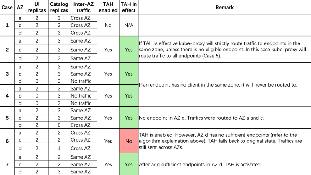
Some further conclusions we can draw from these examples are:
- If TAH is effective, kube-proxy strictly routes traffic to endpoints in the same zone, unless there is no eligible endpoint. In this case, kube-proxy routes traffic to all endpoints.
- If an endpoint has no upstream in the same AZ, then it won’t have incoming traffic. External traffic to NodePort is out of scope of TAH. However, once traffic arrives at the node, it is distributed by kube-proxy, which is affected by TAH as well.
- TAH won’t affect headless services, and all endpoints will be resolved by kube-dns.
- Number of pods in each AZ should be in proportion to the number of vCPUs in the same AZ. An optimal situation would be to have nodes equally distributed among AZs, and pods are spread among AZs by Topology Spread Constraints.
Cleaning up
You can delete created resources to avoid additional cost. It’s simple to delete all resources at once as they are deployed using Terraform. Run the following command:
Now you have deleted all resources created during the walkthrough. You may also want to check if there are any dangling Elastic Load Balancing (ELB) on AWS Console. You can safely delete it if you find any.
Conclusion
In this post, we showed you an overview of how TAH works, and how TAH impact to workloads running on Amazon EKS. The TAH feature is a Kubernetes-native way to attempt to route traffic within the same zone as it originates, and is available as of Amazon EKS v1.24. By using TAH in your architecture, you can reduce latency and inter-AZ data transfer costs, while still gaining benefits from the resiliency of a multi-AZ architecture. However, due to the overload mechanism, TAH can only be used when workloads are evenly distributed between AZs.
For more information, you can see Document of Topology Aware Routing on Kubernetes documentation for you reference. Please be noted that Kubernetes is under continuous development, and the behavior of TAH may change in further version. Stay tuned on AWS Containers Blog for further update.