Containers
On-premises egress design patterns for Amazon EKS
Introduction
When adopting a Kubernetes platform, architect teams are often highly focused on INGRESS traffic patterns. Why? Kubernetes has a first-class support for in-cluster traffic flows as well as into-cluster traffic flow implemented by ClusterIP and the INGRESS constructs .The object model allows the load balancing of Kubernetes pods natively and also extends the constructs to allow an integration with Elastic Load Balancing (ELB) services using the controller model. It goes even further; the Kubernetes INGRESS object allows us to specify configuration for Layer 7 traffic routing such as path-based/host-based and Transport Layer Security (TLS) termination. Recently the SIG-NETWORK community introduced Kubernetes gateway API, which is a new model for Kubernetes service networking, defining a new way for vendors to model networks of services. With Amazon Elastic Kubernetes Service (Amazon EKS), customers can use Amazon VPC Lattice through the use of AWS Gateway API controller, which is an implementation of the Kubernetes Gateway Application Program Interface (API).
Solution overview
The challenge: What about egress traffic?
In Amazon EKS, egress use cases range from simply providing internet egress connectivity for Pods located on Virtual Private cloud (VPC) Private Subnets (i.e., the common use case), to fine-grained rule based L4/7 egress connectivity to the internet or remote on-premises networks.
The first use-case is solved well with the implementation of the resilient, scalable, Network Address Translation (NAT) service (Public). The latter use-case is considered more advanced and in addition to the L4 connectivity, which often mandates configuration of fine-grained egress patterns. In those patterns often Pods are required to access only a set of permitted upstream endpoints.
In the traditional egress architectures, the source IP address is still used by on-premise firewalls as the identifier of a certain system or service, and is used for controlling access. In the new world of containers, Pods and IP Addresses are an ephemeral resource, yet organizations simply aren’t yet able to modernize existing legacy applications. Therefore, a balanced approach is required.
It is worth mentioning that in-cluster controls are covered well by using Kubernetes network policies. From our experience, there’s no typical phase where organizations adopt Kubernetes. Our customers tell us that they are adopting Amazon EKS to host their most mission critical workloads, from financial institutions to large telecommunication companies.
Those customers often operate in large complex brownfield environments, where on-premises workloads are constantly migrated to AWS in a gradual manner. One of the recurring patterns we’re able to observe is a networking team, which hands out specific network ranges to platform teams deploying Amazon EKS on AWS.
For these cases, we’re able to observe a recuring requirement to align certain applications and services with a dedicated egress (RFC 1918) Source IPs, which are expected to remain fixed and used in on-premises firewall as an access identity.
This requirement often leads to a friction between the networking and platform teams. The platform team is pulling toward application-level constructs that solve the challenge (i.e., application-level identity, authentication, and authorization). The aim is to reduce the dependency on ephemeral Pod networking IPs.
At the same time, the networking team defines the source IP as the downstream identity, which can be due to lack of strong application-level identities or traditional organizational policies.
Let’s look at the following figure, which depicts this challenge.

Figure 1. Upstream network firewall and router expects single source IP per tenant, application, and service
In the next part of this post, we’ll showcase four design patterns that can be used to adhere to the networking team requirement and state the advantages and considerations for each pattern.
Our goal is to provide the insights that allow you to make an informed decision on which pattern to choose.
Design pattern 1: VPC Subnet CIDR as source
In the pattern shown in the follow figure, the VPC is carefully crafted to collocate Amazon EKS worker nodes into dedicated subnets spanning two or more distinct availability zones (AZs). To couple the Kubernetes (i.e., logical) with the physical (i.e., subnets), we define a nodeGroup per workload and spin up worker nodes in this nodeGroup with a proper taint (i.e., app-a). The pods are labeled as app-a and configured to tolerate the app-a worker node taint.
Optionally, the app-a Pods could be associated with a Kubernetes namespace, app-a-ns, for further tenant logical Kubernetes level isolation. These are effective at setting in-cluster network policies and/or set namespace-based Kubernetes quotas.

Figure 2. Upstream network firewall/router allow-lists by CIDR range. The app is collocated into specific CIDRs
Advantages
- Simplicity: This pattern can be scaled by adding additional subnets and using Infrastructure as a code (IaC)/GitOps to associate the logical (i.e., Kubernetes) with the physical (i.e., additional VPC Subnets)
- Classless Inter-Domain Routing (CIDR) as source: The allow-list primitive is a Subnet based on CIDR, rather than Pod IPs that are ephemeral
- Network team: A common pattern that the upstream network administrative team are familiar with and requires no changes on their end
Considerations
- Security: The upstream access (via the firewall allow-list rules) means that the upstream firewall is required to completely trust the downstream Kubernetes scheduling constraints resulting a coarse-grained nature upstream firewall rules (CIDR) that leads to lack of granularity in the access permissions. Essentially, pods are scheduled into the respected worker-nodes using standard Kubernetes Taint & Tolerations, which are simply YAML configurations. To mitigate a possible configuration exploit, unintentional mistakes that may lead to unauthorized access it is advised to implement strong controls along the application pipeline. A good start would be a configuration validation for your continuous integration (CI)/continuous deployment (CD) pipeline (as left as possible), to runtime controls, which blocks the scheduling of Pods with the incorrect taints and target namespace assignment. This can be achieved with Policy-as-a-Code engines such as Open Policy Agent (OPA)/Gatekeeper or Kyverno). In use cases where teams are assigned full ownership on namespaces, it is advisable to add fine-grained Kubernetes Role-based access control (RBAC) controls to scope namespace permissions (i.e., least privilege approach).
- Efficiency: The Kubernetes constraints and VPC design may lead to under-utilized Amazon EKS worker nodes, which may lead to a non-cost optimised architecture, this can be mitigated with right sizing Amazon Elastic Compute Cloud (Amazon EC2) instances.
- Scale and complexity: Upstream Application access sources scale with adding multiple subnets across distinct AZs. In a large-scale multiple upstream applications deployment, the VPC CIDR needs to be planned carefully to allow applications growth. In brownfield environments, this could be a challenge. Mitigation is possible by taking the custom networking approach.
- Pod source IP: The Pod source IP will be subject to Source NAT (i.e., the VPC-CNI default behavior), using the primary private IP of the Amazon EC2 instance it resides on.
When should I consider to adopt this pattern?
When your architecture is hybrid and there are a relatively low number of legacy applications access patterns. Another use-case could be a migration and/or modernizing phase where you are mandated to support those legacy applications traditional access.
Design pattern 2: VPC Subnet CIDR as source, routed via private NAT gateway
In this following figure, the pattern we use the same VPC Subnet, nodeGroup, and namespace logical isolation model (Figure 1). For egress, we take the centralized Source Network Addresses Translation (SNAT) approach.
We deploy a highly available, resilient Private NAT gateways that spans at least two subnets in distinct AZs. We then use standard VPC subnet routing tables to route the default gateway via the respective Private NAT gateway.

Figure #3 upstream network firewall/router allow-lists by Private NAT Gateways, apps are mapped to Private NAT Gateways
Advantages
- Architectural flexibility:
- Upstream firewall allow-List: The allow-list contains very few Private IPs representing the corresponding NAT Gateway as source, which allows a fine-grained permission control.
- Consolidation: Logically supports common applications upstream access profiles by controlling the access using a route to the specific NAT Gateway. In simple words, multiple applications that may share a common upstream access pattern could be logically combined by sharing the same route to the NAT Gateway. (No changes at upstream are required).
- Overlapping CIDRs: The worker node CIDRs could overlap with the on-premises network CIDR. All the nodes and pods egress are subject to SNAT using the private NAT Gateway Primary IP as the Source. (The NAT Gateway subnets must not overlap with the on-premises network CIDR).
- Egress SNAT de-coupling: this pattern uses a centralized purpose-built NAT service that carries the entire SNAT load, thus offloading it from the worker node (Amazon VPC CNI plugin). The default behaviour for the VPC-CNI is to SNAT any egress Pod traffic destined outside the VPC CIDR with the worker node primary IP Address. When using this pattern, the VPC CNI SNAT could be turned-off. Please see this documentation for further information.
- Operational offload: The NAT Gateway is a fully managed service. The service also scales as the demand grows (see service characteristics and limitation).
Considerations
- Security – See Figure 1.
- To mitigate a possibility of clients which bypass the NAT gateway or connect to their non-mapped NAT gateway, it is a good practice apply Kubernetes network polices that limit the pods and namespace to egress only the corresponding NAT Gateway.
- Application networking: This pattern uses L4, which has no application networking awareness (L7) and requires the administrator to craft the VPC, subnets, and routes according to the application access pattern logic.
- Cost: The NAT gateway service has multiple price dimensions.
In high volume of data processing (1GB units of data processed by the NAT gateway), This pattern may generate high data transfer costs. - Scale and complexity – See Figure 1.
- VPC design: As an application is mapped to a private NAT Gateway construct, the Private NAT Gateway subnets CIDR should be large enough to accommodate future growth and scale of NAT Gateways.
- Pod source IP: The Pod source IP is subject to Source NAT using the Private NAT Gateway assigned Primary Private IP.
When should I consider to adopt this pattern?
If the sheer number of applications and their access patterns are few and the aggregated traffic volume isn’t generating a cost challenge, then this pattern may be a good fit. An additional use case could be that the upstream network CIDR overlaps with the VPC CIDR, You could add an additional CIDR to the existing VPC and deploy the NAT Gateway service onto subnets created from this new secondary VPC CIDR.
Design pattern 3: Egress IP/Gateway using alternate compatible CNI plugin
In this pattern, the Amazon EKS cluster uses the Isovalent Cilium CNI (an Alternate compatible CNI plugin).
Cilium (and some other alternate compatible CNI plugins) offers a construct called Egress IP/ Gateway. Cilium’s egress gateway is able to dynamically SNAT the incoming Pod source IP in a performant manner using the eBPF engine.
The SNAT Egress IP criteria may include Kubernetes Pod Labels as sources to SNAT using specific Egress IP/Elastic Network Interface (ENI). See Cilium’s official docs for more information.
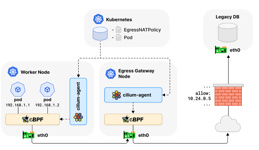
Figure #3 upstream network firewall/router allow-lists of source IPs which will undergo Source NAT
The diagram was taken from cilium’s official docs
Advantages
- Kubernetes constructs tight integration: This pattern offers a flexible Kubernetes object-level integration.
- Performant: The SNAT is handled on the Egress Gateway using Extended Berkeley Packet Filter (BPF) constructs, as opposed to the classical IPtables based masquerade.
- Simplified Architecture: Subnet, NodeGroup, and namespace logical isolation and scheduling constraint for pods and nodes (Figures 1 and 2) aren’t mandatory to cover the egress IP use-case when using this pattern. Egress traffic traversing the gateway applies an EgressNATPolicy that evaluates the source based on Kubernetes constructs such as Pod Label, in turn will wire the configurable egress IP to SNAT.
Considerations
- Security – In addition to Design Pattern #1, using Pod Selector allows a greater flexibility and the source security dimension becomes a Pod Label. It is recommended to implement strong controls to validate that Pods cannot be mislabeled or misallocated to the wrong namespaces which will allow an unauthorized upstream access.
- High availability: The Egress gateway runs on an in-cluster Amazon EC2 instance because “everything fails, all the time”. The recommended architecture should be multiple redundant Egress Gateways spread across distinct availability zones. Cilium offers an Egress Gateway High Availability (HA) Pattern. contact Isovalent for more information on this pattern.
- Scale: On high connection rate egress connectivity patterns, it is advisable to choose Amazon EC2 instances that are network-optimized, and carefully monitor the networking primitives.
- Expectations: Cilium expects the administrator to set, manage, and monitor the entire operational aspects of the Amazon EC2 instances that are used as egress gateways.
- Current Limitations: AWS Fargate Pods are not supported.
- Support: Cilium is an alternate compatible CNI plug-in and isn’t supported by AWS. AWS only supports the VPC-CNI Add-On with Amazon EKS. We recommend to obtain commercial support from isovalent in this case.
When should I consider to adopt this pattern?
If the sheer number of applications and access patterns is large and the current brownfield AWS environment can’t be crafted to meet the upstream environment, then this pattern may be a good fit.
Design pattern 4: Egress Gateway with service mesh
In this pattern, We deploy istio (i.e., service mesh) inside the Amazon EKS cluster. We deploy Istio with its Egress Gateway construct, as shown in Figure 4. The Egress Gateway can be viewed as a horizontal scalable service that implements just the envoy instance and its sole purpose is to control the mesh outbound traffic. The gateway is integrated into Istio’s service mesh core constructs, which allows the administrator to create fine-grained L7 rules and policies on how to route and authorize traffic from meshed services to services that reside outside of the mesh boundary.
This pattern uses five istio constructs (ServiceEntry, Gateway, VirtualService, DestinationRule, and AuthorizationPolicy), It is beyond the scope of this post to go deeper. To learn more, here is a good starting point and a full example.

Figure 4. Upstream network firewall/router allow-list authorizes Istio egress gateways. (L4), L7 routing, and authorization is done by Istio at source
Advantages
- Scalability: The SNAT is handled on the Egress Gateway, which are envoy Pods. Those Pods are horizontally scalable using Horizontal Pod Autoscaler (HPA).
- Application networking: The Egress Gateway is L7 aware, which allows it to support fine-grain authorization and accept routing policies that brings it closer to the application logic.
- On boarding new applications: Each VirtualService is part of the Mesh and is subject to fine-grained upstream connectivity under the authorization and routing polices. Adding a new service involves creating five istio constructs and a Kubernetes namespace, which can be fully automated using GitOps. The underlying (L4) constructs (VPC, Subnets, Security groups) remains in-tact.
- Upstream network: The upstream firewall and router allow-list includes solely the downstream istio egress gateway networks (i.e., VPC Subnets)
Considerations
- Security – See Pattern #1
- Architecture (Egress Gateways): The Egress gateway Pods are running on Amazon EC2 Worker Nodes. It is advisable to:
- Isolate the Egress Gateway Pods into their own subnets that span at least two distinct AZs.
- Deploy the Egress Gateways into:
- A dedicated Amazon EKS-managed node group
- A dedicated Kubernetes namespace
- Configure Taints and Tolerates to collocate only Egress Gateway Pods
- Set Pod spread constraints to achieve pod-level high availability
- Scale: For on high connection rate application egress connectivity patterns, it is advisable to choose Amazon EC2 instances that are network-optimized and to carefully monitor the networking primitives.
- Security consideration: istio is unable to securely enforce that all traffic flows through the egress gateways. Please see ways to mitigate.
- Support: istio is a Cloud Native Computing Foundation (CNCF) Graduated project and comes with its complexity. Known to work (well) with Amazon EKS, but not supported by AWS. We advise you to evaluate the tradeoffs and asses the learning curve required to successfully implement, maintain, and support production istio environments. Tetrate is an AWS Technology Partner who offers commercial support for istio.
- Current Limitations: AWS Fargate Pods are not supported.
When should I consider to adopt this pattern?
If the sheer number of upstream applications and their access patterns are high and/or the application access patterns are dynamic, then using this pattern will be a good fit. An additional reason for using this pattern could be an AWS brownfield environment where the VPC design can’t be changed to meet the upstream requirements. We have also seen use cases where customers migrated upstream application in a gradual manner using this pattern.
Conclusion
In this post, we showed you four uses cases of Egress Architecture Patterns that solve the egress source IP challenge. We believe that using Source IP as an identity is a traditional pattern that quite often forces inefficient designs and leads to security challenges, operational overhead, and cost optimization challenges. It is also important to mention that security and network teams must be part of the pattern discussions and decision loop, because they represent the organizational security policy. It’s an organizational policy that drives security and architecture and not the opposite.
As a path forward, we observe organizations that draft a short to mid-term plan where they start with a Layer 4 based patterns, then gradually migrate to Layer 7 based. They work collaboratively with the network and security teams to approve patterns and set mid- to long-term goals.