Networking & Content Delivery
Introducing AWS Gateway Load Balancer: Supported architecture patterns
Customers often ask me how they can maintain consistent policies and practices as they move to the cloud, especially as it relates to using the network appliances. They trust third-party hardware and software appliances to protect and monitor their on-premises traffic, but traditional appliance deployment models are not always well suited to the cloud. Last year, AWS released VPC ingress routing, making it easier to route traffic to specific EC2 instances within a VPC. This was a step forward, but customers still wanted the ability to target a load balancer and Interface VPC endpoints (such as AWS PrivateLink) in a VPC route table. By combining a transparent network gateway and a load balancer, the new AWS Gateway Load Balancer meets this requirement, creating a new way to deploy, scale, and provide high-availability for third-party virtual network appliances.
Network appliances sit in line with network traffic and inspect incoming and outbound traffic flows. The most common use case is to insert a network firewall, but functions can vary from deep packet inspection, enforcement, optimization, packet or payload manipulation, or non-intrusive visualization and tracing. This type of transparent insertion has many names, service chaining, bump-in-the-wire, and network functions virtualization.
Industry leading partners
One thing you may have noticed, is that in this post I refer to “third-party” virtual appliances specifically. One way Gateway Load Balancer is unique is that it is designed for virtual appliances from AWS Partners and ISVs in AWS Marketplace. This is an important part of the value Gateway Load Balancer provides. You can find, test, and buy virtual appliances from third-party vendors directly in AWS Marketplace. By creating this integrated experience, we hope to remove friction from the deployment process, so you see value from your virtual appliances more quickly—whether you want to work with the same vendors you do today, or test another options. We’re excited to be working with industry leading partners at the launch of Gateway Load Balancer. Before we jump into the supported architecture patterns I want to highlight the great things they have been doing:
- Check Point Software – blog >>
- Fortinet – blog >>
- Palo Alto Networks – blog >>
- Radware – blog >> | blog >>
- Trend Micro – blog >>
- Valtix – blog >>
- cPacket Networks – blog >> | video demo >>
- Glasnostic – blog >>
- NETSCOUT Systems – blog >> | video demo >>
- Aviatrix – blog >>
- Cisco Systems – blog >>
- HashiCorp – partner profile >>
- ePlus Technology, Inc. – partner profile >>
Introduction and core concepts
OK, let’s take a look at the core components and concepts surrounding Gateway Load Balancer.
Control and data plane: In any technology system you are typically going to be dealing with a control plane and a data plane. You can think of the control plane as the brain, the configuration, the rules. You can think of the data plane as the worker doing the work, pushing the packets, and filtering the traffic. In almost any system there will be both control and data plane components. These are not mutually exclusive. Typically, when customers ask for centralization, they are looking for control-plane centralization, and don’t consider the data plane until performance, cost, or reliability come into play.
Appliance: This is the “bump-in-the-wire” function that sits in the network path. These can be firewalls, inline analytics, or other inline functions that have traditionally been referred to as network appliances. In the cloud these are virtual appliances (instances or partner solutions that you can access via AWS Marketplace).
Gateway Load Balancer (GWLB): A managed service that makes it easy for customers to deploy and manage a fleet of horizontally scalable inline network virtual appliances in a transparent manner for purposes such as security inspection, compliance, policy controls, and other networking services.
Gateway Load Balancer Endpoint (GWLBE): This is a data plane component of the GWLB and provides a way for customers to flexibly place interface VPC endpoints in both centralized and distributed deployments. A GWLBE is similar to AWS PrivateLink, which allows you to place your service across many accounts and VPC’s without losing centralized control and administration.

AWS Transit Gateway appliance mode: Some network appliances, such as stateful firewalls, require visibility to a network flow’s bidirectional transaction in order to assess valid traffic from potential threats or attacks. For these scenarios asymmetric routing can hinder the effectiveness of stateful solutions. By default, the AWS Transit Gateway attempts to isolate traffic within the availability zone the traffic originated. While this behavior is optimal for most architectures, it is not ideal for centralized stateful firewall implementations that span multiple availability zones. It can introduce asymmetric routing which can result in traffic disruption. To solve this problem the AWS Transit Gateway now supports appliance mode. Appliance mode ensures bidirectional traffic forwarding to the same VPC attachments, also known as symmetric routing. This removes the need for complex workarounds, such as source-NAT, to force traffic to return to the correct appliance. We will dive into this in more detail later.
Architecture patterns for inline inspection
Customers that are implementing inline appliances typically fall into one of three architectural patterns. To maintain consistency across the various examples we will use a firewall appliance to help describe the use-cases. However, keep in mind this could be any type of inline function.
-
- Single VPC with north/south connectivity
- Many VPC’s with centralized north/south connectivity
- Many VPC’s with centralized east/west connectivity
The terms north/south and east/west have been used for years in traditional networking and data center environments to help describe the flow of traffic. North/south generally refers to traffic leaving your network or the data center, and is most commonly describing traffic that is coming from or going to the internet. East/west refers to traffic flowing between resources within your data center or network. These metaphors also apply in AWS where a single VPC or collection of VPC’s acts as a virtual data center and network.
Single VPC with north/south connectivity: This model represents a VPC that requires a firewall or other inline function to be placed between resources inside the VPC and outside of the VPC such as over the Internet. In this model you have the flexibility to centralize or distribute the control plane and maintain a distributed data plane.

Distributed control and data plane (GWLB + GWLBE)

Centralized control plane (GWLB) distributed data plane (GWLBE)
This architecture pattern supports placing a firewall or other inline auto-scaling appliance fleet in between the VPC’s Internet Gateway and a public IP address such as an Elastic IP. The public IP can be associated directly to an EC2 instance, AWS NAT Gateway, Application or Network Load Balancers, or other addressable resources within the VPC.
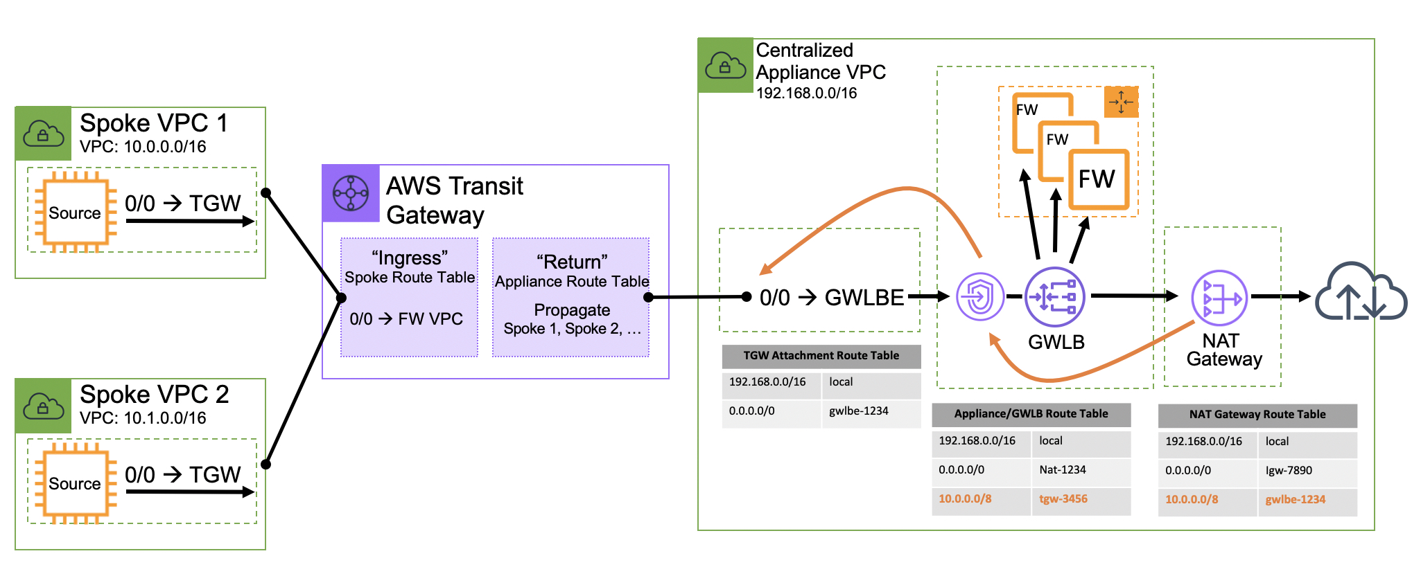
Many VPC’s with centralized north/south connectivity: This model is also focused on connectivity out of VPC’s over primitives like the AWS Internet Gateway and Direct Connect, or VPN via AWS Transit Gateway. This would apply the inline bump-in-the-wire functionality in a centralized VPC. This is typically accomplished with the AWS Transit Gateway to help control separation of duties between accounts that are performing the inline functionality, and the spoke VPCs that are hosting applications. In this pattern both control and data plane functionality are centralized.
Centralized north/south connectivity
Many VPC’s with centralized east/west connectivity: This model addresses connectivity between two or more VPCs and is often times combined with the centralized north/south connectivity model over the AWS Transit Gateway.
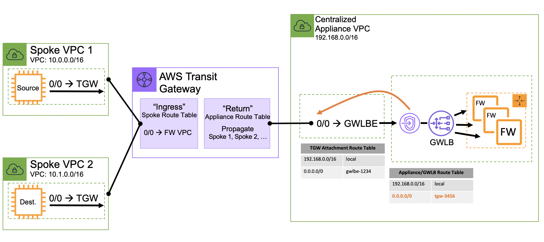
Centralized east/west (inter-vpc) connectivity
There is a fourth option that we have not addressed above, which is a single VPC that requires some sort of inline east/west functionality between subnets in the same VPC. Today this is not supported because the VPC does not allow more specific routes than a VPC’s CIDR allocation to be defined within a VPC route table. For example, if you assign a VPC with the CIDR allocation 10.0.0.0/16 you cannot enter a route table entry for something that is more specific such as 10.0.1.0/24. Because of this, a VPC route table does not allow you to redirect traffic through an appliance if the source and destination are in the same VPC. If this functionality is desired you may want to consider segmenting these untrusted dependencies in different VPC’s, or utilizing instance or host-based solutions such as security groups or third party software agents. There is one exception to this rule and it applies to edge routing tables. An edge routing table allows you to force traffic entering a VPC from an Internet Gateway through a Gateway Load Balancer. This is referred to as ingress routing. You can read more about ingress routing and edge routing tables here.
*Side note: When this blog published, VPC ingress routing with edge route tables are only supported on the Internet Gateway and are not supported on the Virtual Gateway.
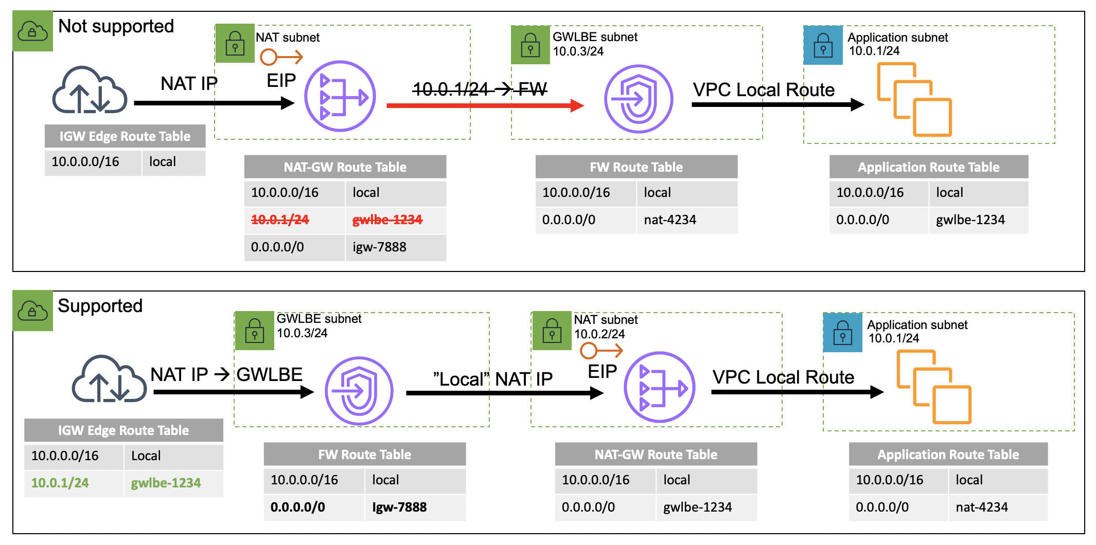
For this same reason it is important to consider the placement of your inline functions for internet bound workloads as well. If you are using an AWS NAT Gateway or self-managed NAT instances the GWLBE must reside between the Internet Gateway and the publicly-facing resource directly. To be specific, for traffic coming in from the internet, you cannot place the inline functionality or GWLBE after the NAT and in-between your private instances as it would require a more specific route within the VPC route table. This can present a problem for certain use-cases that require the appliance to have visibility of the backend resources IP address instead of the NAT resources IP address. If you require instance level visibility you should consider the centralized north/south option discussed above.
VPC local route preference and distributed GWLBE/NAT placement
Stateful firewalls…require state
Asymmetric routing is a term that describes when a client’s request to a server traverses a different network path than the server’s reply. If the asymmetric return path sends the packet through a different firewall valid traffic could be discarded due to something called connection tracking–a core component of stateful firewalls. A stateful firewall tracks a connection or network flow for the entire length of a transaction (such as with TCP connections from the initial SYN packet to the final FIN notification). For a firewall to track a connection effectively the network must ensure that packets are sent to the same firewall instance in both directions (client-to-server, and server-to-client). If for any reason an active flow gets routed to a firewall that is not tracking the flow’s state it can lead to unwanted packet drops.
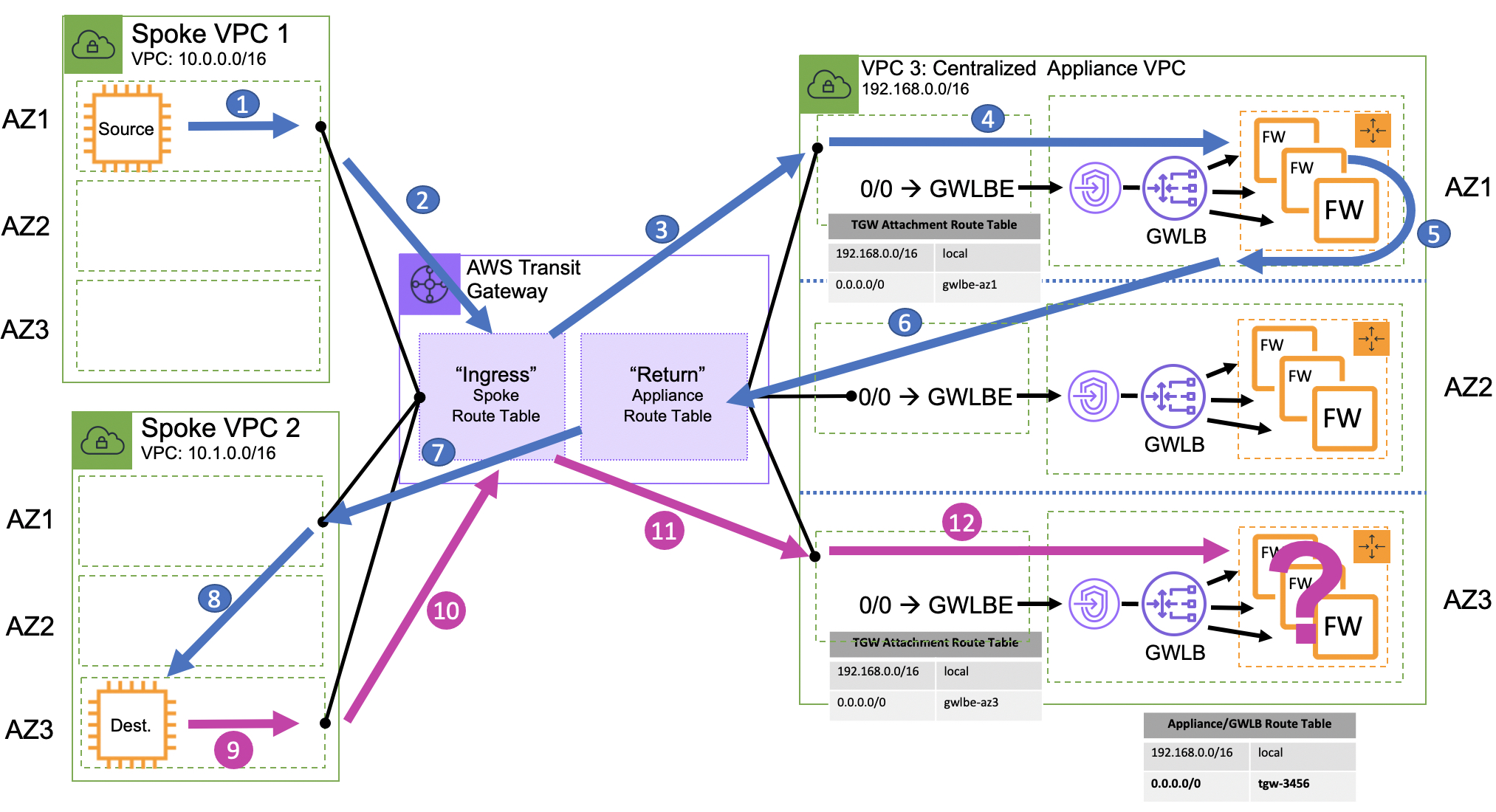
By default, the AWS Transit Gateway applies a very specific routing algorithm that is optimized to maintain availability zone affinity. While this is ideal for performance and availability it can present problems for the centralized firewall architectures we are discussing in this blog. This is especially true in the centralized east/west architecture pattern where the source and the destination might be in two different availability zones.
Stateful firewall’s with asymmetric routing
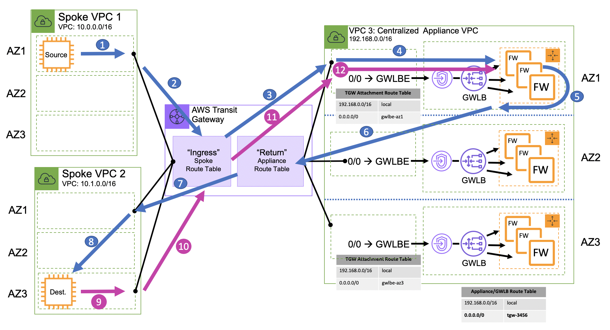
In the diagram above there are three VPC’s. Spoke VPC 1 (where the source of the traffic is), Spoke VPC 2 (where the destination of the traffic is), and VPC 3 (where the centralized firewall is configured). The AWS Transit Gateway in the middle is setup to route all traffic from spoke VPC’s to the centralized firewall VPC, and all traffic from the centralized firewall VPC back to the correct spoke VPC.
When the source initiates a connection to the destination, the packet is directed to the AWS Transit Gateway attachment in the same availability zone. The Transit Gateway then forwards the packet to the centralized firewall VPC (based on the AWS Transit Gateway’s routing table rules) out the attachment in the same availability zone as long as one exists, otherwise it will load balance across available attachments in other, non-local availability zones. The centralized firewall VPC is configured to send traffic to a specific firewall endpoint and back to the AWS Transit Gateway.
So far everything has remained in availability zone 1. The AWS Transit Gateway will then send the packet out the attachment in Spoke 2 VPC in availably zone 1. From there the packet will cross the availability zone boundary to its destination in availability zone 3. When the destination initiates the reply back to the source it is directed to the AWS Transit Gateway attachment in availability zone 3 and is then forwarded to the centralized firewall VPC on the attachment in availability zone 3. This is where things get tricky.
Before GWLB, customers had to choose between a single instance design or perform source-NAT on each appliance to ensure the return path is forced to the correct firewall instance. These scenarios are not ideal as they limit scalability, availability, and performance. Some organizations have implemented more complex workarounds with NAT and additional layers of VPN tunneling as discussed in How to integrate third-party firewall appliances into an AWS environment. This comes with significant cost and operational burden.
With GWLB, you can scale your inline appliance fleet per availability zone, significantly improving both reliability and scalability. But how do you scale beyond a single availability zone in a centralized architecture without causing the asymmetric routing issues described above? This is where the new AWS Transit Gateway appliance mode comes in.
With the AWS Transit Gateway appliance mode, you have the ability to specify attachments that should forward network flows out of the same availability zone regardless of the flow’s direction and what availability zone it originated. The AWS Transit Gateway Appliance Mode ensures that network flows will be symmetrically routed to the same availability zone and network appliance. (You can read more about AWS Transit Gateway appliance mode here.)
Symmetric routing with AWS Transit Gateway Appliance Mode
Deciding which architecture is best for you:
Deciding on the architecture pattern that is right for you is highly dependent on how you prioritize the five pillars of the The AWS Well-Architected Framework. Every architecture pattern has both advantages and disadvantages that have to be considered. For cost optimization you need to do the math. The GWLB has two cost components, an endpoint-hour and data processing. The number of VPC’s and the volume of traffic processed will dictate which architecture is more cost effective. For operational excellence, the best architecture is often the one that you can best manage and operationalize. Depending on your organizational structure you may find that the centralized approach allows you to maintain a solid separation of duties. If this is the case you need to ask yourself if you want to separate the control and management plane, the data plane, or both.
So far, we have addressed some of the foundational elements of scaling inline bump-in-the-wire functionality with the Gateway Load Balancer. Check out another blog on this topic, Scaling network traffic inspection using AWS Gateway Load Balancer, and stay tuned for future posts that will address how to implement GWLB and GWLBE for internet ingress and egress filtering, or as we described above, north/south connectivity in both centralized and distributed architectures, and more.
This is just an introduction to what Gateway Load Balancer can do. I encourage you to check out the product detail pages and faq. You might also want to check out this video demo that walks through five steps of setup and testing, and check out the code samples published in this Github repository.
 Justin Davies
Justin is a Principal Solutions Architect and Network Specialist for Amazon Web Services (AWS) based in San Diego, California. He has over 15 years of experience designing, implementing, and operating service provider network architecture and application connectivity.