Containers
Deploy geo-distributed Amazon EKS clusters on AWS Wavelength
Introduction
In December 2019, we announced AWS Wavelength, new AWS infrastructure that allows customers to deploy workload closer to 5G-connected users and devices. Customers can now use AWS Wavelength to deploy Amazon Elastic Compute Cloud (Amazon EC2) instances, Amazon Elastic Kubernetes Service (Amazon EKS) clusters and a suite of supported partner solutions available on the AWS Marketplace.
The value proposition of AWS Wavelength was simple: the closer the workload to the end user’s device, the lower latency and more reliable network performance could be unlocked. However, we could never have imagined some of the innovative use cases from our customers to use the power of both 5G and mobile edge computing.
As an example, previously distinct mobile apps (e.g., eCommerce, video chat, and 360-degree streaming) now converge into a single mobile experience with the exponential increase in bandwidth afforded by 5G millimeter wave connections. Beyond high-immersive user experiences, 5G and AWS Wavelength provides opportunities to drive social impact and digital inclusion. With near-real time computer vision for business-to-business (B2B) applications, retailers and large-scale venues can bridge the communication gap for the hearing or visually impaired communities by translating American Sign Language into the spoken word — and vice versa — using machine learning.
From an implementation perspective, application builders were tasked with defining from scratch what mobile edge compute architecture should look like. Early on, one of the pieces of collective feedback from our customers was that a solution was needed to remove the complexity of managing highly geo‑distributed mobile workloads. While some customers opted to manage AWS Auto Scaling groups for each AWS Wavelength Zone, this approach quickly became unwieldy as the number of AWS Wavelength Zones increased.
As a result, Amazon EKS has quickly become the architecture of choice for mature edge applications. With a single Control Plane orchestrating containers across an entire AWS Region, developers use a single pane-of-glass to deploy workloads across all the Availability Zones (AZs) and AWS Wavelength Zones within a given region.
In this post, you’ll learn about AWS Wavelength and how Amazon EKS can be used to deliver highly geo-distributed applications for low-latency application access.
Solution overview
Through AWS Outposts, Local Zones (LZs), and AWS Wavelength, new infrastructure services can deliver a consistent experience to support applications with low latency or local data processing requirements. While AWS Outposts is designed to select applications that remain on-premises, both LZs and AWS Wavelength Zones offer compute and storage services with lower latency than traditional AZs can provide.
What makes AWS Wavelength Zones especially unique is its network architecture. Unlike Availability Zones (AZs), each AWS Wavelength Zone isn’t interconnected to one another and thus resembles a hub-and-spoke topology.

AWS Wavelength Zones are logically isolated data centers, within the telecommunication providers’ networks, that are connected back to the AWS Region via redundant, low latency, and high-throughput connectivity. This directly contrasts the networking model of AZs where, in the absence of restrictive network access control lists (NACLs), one can expect full mesh connectivity. Each AZ can seamlessly connect to one another either via Private IPs within the virtual private cloud (VPC) or via Public IPs via the Internet Gateway.
Moreover, many customers assume that LZ and AWS Wavelength Zones can be seen as interchangeable for low-latency edge computing. While both infrastructure solutions can be used to satisfy low-latency applications or stringent data residency requirements, the application access pattern is what uniquely differentiates the two services. While LZs are designed to offer multi-access connectivity, regardless of the end device’s mode of access (i.e., 5G vs. Wi-Fi) or mobile carrier, AWS Wavelength Zones is accessible only via the wireless network of the partner supporting the AWS Wavelength Zone. As a result, a consumer cloud gaming application may be most optimal for LZs whereas an Internet-of-Things (IoT)-based agriculture technology solution may be most performant with AWS Wavelength.
To bring AWS Wavelength’s hub and spoke model to life, consider the following: for each Parent Region supporting AWS Wavelength, two or more AZs could each connect to one or more AWS Wavelength Zones, separated by up to hundreds of miles. As an example, the N. Virginia (us-east-1) region supports both a Miami and Boston Wavelength Zone — each of which are separated by 1,000 miles!
By demonstrating the traffic flows behind this unique hub-and-spoke architecture, AWS Wavelength provides the foundation to design some of the most effective geo-distributed workloads to date, if carefully managed.
Wavelength zones and carrier IPs
Much like AZs, subnets launched within AWS Wavelength Zones are allocated a Classless Inter-Domain Routing (CIDR) range within the customer’s VPC CIDR and don’t require customer-owned IP addresses (i.e., AWS Outposts). However, these private IP addresses inherit some special properties within mobile environments. First, Private IP addresses within an AWS Wavelength Zone can’t communicate with Private IP addresses within a second Wavelength Zone; this traffic flow is blocked at the service-level and not supported. However, two subnets within the same AWS Wavelength Zone (e.g., public/private subnet within the same AWS Wavelength Zone) can inter-communicate. For traffic flows destined to the public internet or mobile devices, the Carrier Gateway is used for network address translation (NAT) from Private IP addresses to Carrier IP addresses.

For each AWS Wavelength partner — such as Verizon, Bell Canada, and Vodafone, among others — pools of IP addresses corresponding to the carrier’s packet core in that given geography are exposed as Carrier IPs. Much like Elastic IPs, Carrier IPs can be attached to network interfaces, auto-assigned at launch (via Amazon EC2 Console), or allocated/de‑allocated as the customer sees fit. From a pricing perspective, un-allocated Carrier IP addresses is charged per hour used.
With a broader understanding of the carrier network VPC architecture, we wanted to provide customers a readily available Amazon EKS deployment guide specifically for AWS Wavelength environments. This post captures 2-years-worth of customer feedback, best practices, and holistic lessons learned from their environments.
Amazon EKS reference architecture
Today, Amazon EKS on AWS Wavelength doesn’t support managed node groups or AWS Fargate. As such, it’s critical to note the following design considerations for your cluster:
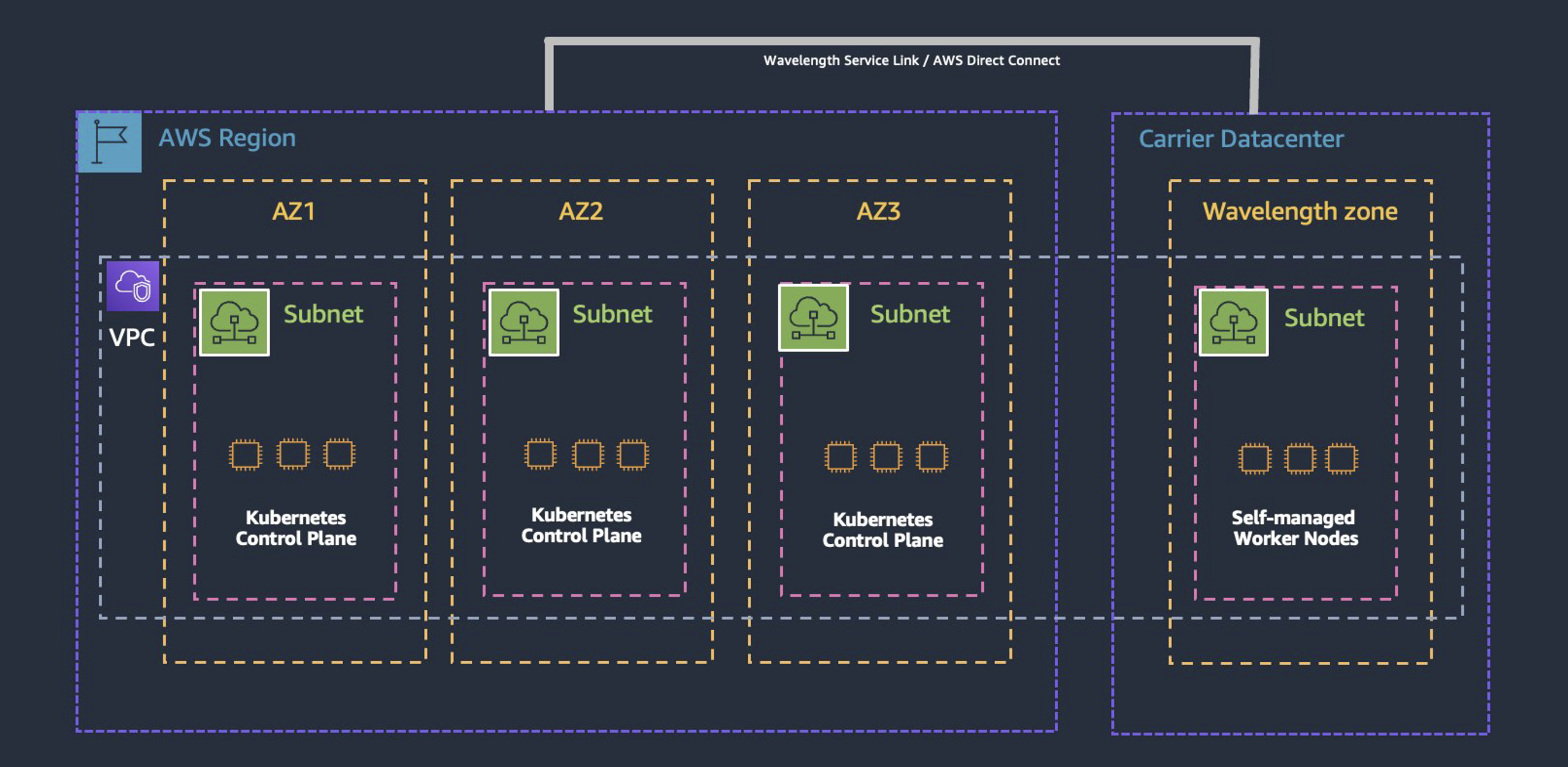
Amazon EKS Control Plane: Much like traditional clusters, Amazon EKS requires two VPC subnets to launch the Control Plane. However, neither of the two subnets can include an AWS Wavelength Zone; and unlike AWS Outposts, Local clusters for Amazon EKS is not supported.
EKS Worker Nodes: To create node groups, we need to launch AWS Auto Scaling Groups running an Amazon EKS-optimized Amazon Machine Image (AMI). This AMI has the kubelet configured to connect back to the Amazon EKS Control Plane in the Parent Region.
Service Link: To connect the worker nodes back to the Control Plane across each AWS Wavelength Zone, the Service Link connects each AWS Wavelength Zone back the Parent Region. Unlike AWS Direct Connect, this connectivity link is abstracted away from the customer. Traffic over the service link is charged similarly to inter-AZ traffic within a region.
Walkthrough
Prerequisites
By default, AWS accounts are not automatically allow-listed access to AWS Wavelength Zones. To access each set of Wavelength Zones on a per-region basis, you can utilize the AWS Console or AWS command line interface (CLI) to opt-in. As an example, you can opt-in to all AWS Wavelength Zones in the us-east-1 Region with the following:
Deploying the Amazon EKS cluster
To deploy your first Amazon EKS cluster to an AWS Wavelength Zone, start by creating an Amazon EKS cluster in the Parent Region using the Amazon EKS User Guide. When selecting your Amazon EKS version number (e.g., 1.21), take note of the version selected. This becomes critical when instantiating the worker nodes because the Amazon EKS-Optimized AMI version should match that of the Amazon EKS cluster Kubernetes version or have a version skew of up to two minor versions. To learn more about the available AMIs, visit Amazon EKS optimized Linux AMIs or Kubernetes Version Skew Policy.
To create the self-managed nodes, you can use eksctl to launch Auto Scaling groups of Linux nodes that register with your Amazon EKS cluster.
Specifically, for self-managed nodes in AWS Wavelength, additional configuration is needed to distinguish the subnets in the Control Plane (e.g., us-east-1a) from the worker nodes (e.g., us-east-1-wl1-bos-wlz-1).
- AWS Wavelength Zone subnets must not have been passed in when you created the cluster. You must create the node group with a config file that specifies the subnets running within the AWS Wavelength Zone.
- The config must also explicitly define the volume type as volumeType: gp2, as only General Purpose SSD (gp2) volumes are supported in AWS Wavelength.
For more information, see Create a nodegroup from a config file and Config file schema in the eksctl documentation.
Troubleshooting the Amazon EKS cluster
Match Kubernetes versions
If you deploy your cluster using eksctl, self-managed nodegroups inherit the Amazon EKS Kubernetes version from the Control Plane (–version=auto). However, outside of eksctl, it’s likely that the selected versions of self-managed nodes could differ from the Control Plane. In select cases, this could cause the node group to fail to register to the Control Plane, resulting in a NotReady state error. To minimize errors, ensure that both the Amazon EKS Control Plane and worker node AMIs match the same Kubernetes version or adhere to the current Version Skew Policy.
Enabling AWS IAM access to your cluster
With select deployment methods, the underlying cluster administrator may assume an AWS Identity and Access Management (AWS IAM) role with different permissions than those assigned to the entity who instantiated the Amazon EKS cluster. As such, kubectl commands may fail unless the appropriate AWS IAM roles are matched to Kubernetes permissions. To grant additional AWS users or roles the ability to interact with your cluster, you must edit the aws-auth ConfigMap within Kubernetes and create a Kubernetes rolebinding or clusterrolebinding with the name of a group that you specify in the aws-authConfigMap.
To learn more about provisioning your ConfigMap, visit Enabling IAM user and role access to your cluster for Amazon EKS.
Amazon EKS cluster endpoint access control
To illustrate another popular deployment scenario, nodes may fail to register with kubectl despite properly configuring the aws-auth ConfigMap. As an example, in the following bootstrap script for an Amazon EKS-Optimized AMI, the kubelet seeks to connect to your HTTPS-based cluster endpoint, which might look something like this:
In this case, the underlying Amazon EC2 instance resolves this fully qualified domain name
FQDN (<https://your-cluster-endpoint>) using the +2 address within the instance’s underlying subnet. How the FQDN resolves; however, is determined by a particular setting within the Amazon EKS cluster’s configuration.

Under API server endpoint access, the cluster defaults to Public access, which routes outbound traffic through the Internet Gateway over the public internet. This means that, by default, unless your worker nodes in AWS Wavelength Zones have attached Carrier IP addresses, the nodes cannot register to the Control Plane.
To remedy this, self-managed nodes in AWS Wavelength subnets can be automatically assigned a Carrier IP address at launch. Alternatively, Carrier IP addresses can be allocated and attached to these self-managed nodes in the Elastic IP section of the Amazon EC2 Console or via the AWS Command Line Interface (AWS CLI).
To achieve the most optimal security posture for you cluster, however, private clusters without outbound internet access are strongly recommended. In this design, no Carrier IPs are needed for the worker nodes and the cluster API server endpoint is resolved by public DNS servers to a private IP address from the VPC. To learn more about this configuration, visit Amazon EKS Private cluster requirements.
In the case that Private cluster access is enabled, AWS Wavelength nodes may still fail to register to the Amazon EKS Control Plane. As a result, the nodes will not show up when running kubectl get nodes as they seek to connect to the EKS Control Plane with no path to do so. To remedy this, create an EC2 interface endpoint and ensure that the Private DNS names is enabled so you can run AWS API calls over AWS PrivateLink and not the public internet.
EC2 interface endpoints are needed because self-managed nodes are not associated with a VPC, so you cannot access the EKS control plane using the DNS endpoint that is available within the VPC. Instead, the EC2 interface endpoints establishes a secure and private connection to the control plane, which allows you to manage and deploy your edge applications to your self-managed nodes.
When configured appropriately, the nodes will register to the EKS control plane with the status Ready.
Cluster DNS resolution
In select cases with worker nodes spanning two or more AWS Wavelength Zones (among other AZs), there are scenarios in which core-dns pods could be scheduled to the Wavelength Zone subnets. In this scenario, a service running in an AWS Wavelength Zone (e.g., us-east-1-wl1-bos-wlz-1) may seek to resolve a service name from a core-dns pod in another AWS Wavelength Zone (us-east-1-wl1-nyc-wlz-1). Given that this traffic flow is blocked, the DNS query would not resolve; moreover, a graceful failover to the other core-dns pod may not occur.
To more deterministically solve cluster-wide DNS support issues, ensure that all core-dns pods in the kube-system namespace are scheduled to the Parent Region. One approach is to add a custom label to the AWS Wavelength Zone worker nodes and then patch the deployment using the broader label, which could span multiple AZs. To start, when your worker nodes invoke the Amazon EKS bootstrap script, add a custom label, which might look something like this:
Next, patch the core-dns deployment with the custom label (parentregion.resources=true) you just created.
Regardless of whether a Parent Region workload is needed, all multi-Wavelength Zone Amazon EKS deployments require at least one node in the Parent Region for core-dns to be scheduled. In practice, highly available workloads should be architected with at least two nodes in the Parent Region and leverage pod anti-affinity rules to tell the scheduler never to place multiple core-dns pods on a single node.
Workload design and solution architecture
Namespace Segmentation
Consider a generalized 2-tier web app with the following required microservices: frontend and backend. To run this application in a traditional Amazon EKS cluster in the Region, the frontend service could be exposed via Application Load Balancer (ALB) and backend could be scheduled to any of the AZs in which the cluster’s node groups are deployed. Assuming no additional ACLs were introduced, each frontend Pod would seamlessly be able to intercommunicate with each backend Pod fear of a select east-west traffic route being blocked.
How could Kubernetes route to each service and ensure cross-Wavelength Zone traffic isn’t attempted?
In the event that separate service names at scale becomes unwieldy (e.g., frontend-wlz19), one approach could be to name your microservices frontend and backend, but utilize a separate namespace for each AWS Wavelength Zone in your architecture. Namespaces allow DNS to natively resolve services, such as frontend, without its FQDN (frontend.wavelength1-namespace.svc.cluster.local).
To ensure that all deployments targeted for a given namespace land within the desired AWS Wavelength Zone, pod affinity rules can be used ensure that the scheduler places a Pod on a node that has a given label, such as topology.kubernetes.io/zone=<your-availability-zone-id>. Using this approach, you can ensure that all deployments targeted for wavelength1-namespace land on nodes within AWS Wavelength Zone 1.

In a separate post, we’ll discuss using service mesh technologies to further isolate edge traffic flows and control for advanced failover and high-availability strategies.
Load balancing
For customers looking for an AWS-native approach, the AWS Load Balancer Controller manages AWS Elastic Load Balancers for a Kubernetes cluster and provisions an AWS Application Load Balancer (ALB) when you create a Kubernetes Ingress. To deploy this solution, visit Installing the AWS Load Balancer Controller add-on.
After configuring the requisite AWS IAM resources and AWS Load Balancer Controller Helm Chart, it’s crucial to add additional annotations to your Ingress resources to ensure that the ALB is deployed in the AWS Wavelength Zone and not in the Parent Region. As an example, if you wanted to deploy an Ingress resource in the wavelenth1-namespace routing all traffic to the frontend service over port 80, then create the following manifest.
Please note the cross-zone load balancing across multiple AWS Wavelength Zones are not supported. As a result, a separate ALB is needed for each AWS Wavelength Zone and can be triggered based on an Ingress that references the frontend service deployed to the same namespace in the respective Wavelength Zone.
To select the most optimal endpoint, traffic could be evenly distributed to these ALBs using a weighted routing policy with Amazon Route 53 DNS records, but this approach wouldn’t take the client’s mobile topology (or geography) into consideration. To embed mobile network intelligence into north-south traffic routing, carrier-developed Edge Discovery Service APIs are critical to the end-to-end architecture and will be covered in a separate post.
Deleting your cluster
As always, if you no longer need the resources, be sure to terminate them. To do so, delete the Amazon EKS cluster and delete the AWS Auto Scaling Group responsible for your self-managed nodes. Additionally, be sure that you delete any EC2 interface endpoints created and release any Carrier IP addresses not attached to any EC2 instances or network interfaces.
Conclusion
In this post, we described a series of best practices to extend Amazon EKS to multiple AWS Wavelength Zones at scale. Across connectivity, security, and availability, we demonstrated popular configurations of Amazon EKS that enables customers to deploy workloads that leverage multiple AWS Wavelength Zones concurrently.
If you are interested in more information about AWS Wavelength, then we encourage you to watch The Cutting Edge: 5G Edge Computing for 5G Applications, a 6-episode Twitch series focusing on a variety of AWS Wavelength topics including featured customers, architectural best practices, and use case deep dives.