Networking & Content Delivery
Best practices for deploying Gateway Load Balancer
As of September 5, 2024, GWLB allows you to configure the GWLB transmission control protocol (TCP) idle timeout from 60 seconds to 6000 seconds. And, GWLB uses either a 2-tuple, 3-tuple, or a 5-tuple hash to define a flow and routes all packets of a flow to one of its backend targets. Refer to the blog post “Introducing configurable TCP idle timeout for Gateway Load Balancer” for more details.
Introduction
At re:Invent 2020, we launched Gateway Load Balancer (GWLB), a service that makes it easy and cost-effective to deploy, scale, and manage the availability of third-party virtual appliances. These appliances include firewalls (FW), intrusion detection and prevention systems, and deep packet inspection systems in the cloud. Since the launch, a lot of customers have deployed GWLB with AWS Partner firewalls in the production environment. This blog post will focus on the most commonly used design patterns and optimal configuration setting as best practices to consider when deploying GWLB:
- Tune TCP keep-alive or timeout values to support long-lived TCP flows
- Enable Appliance Mode on AWS Transit Gateway to maintain flow symmetry for inter-VPC traffic inspection
- Understand when to use Cross-Zone Load Balancing
- Understand appliance and AZ failure scenarios
- Choose one-arm or two-arm firewall deployment modes for egress traffic inspection
- Choose one-arm or two-arm firewall deployment modes for SSL/TLS traffic inspection
1. Tune TCP keep-alive or timeout values to support long-lived TCP flows
Some applications or API requests, such as synchronous API calls to databases, have long periods of inactivity. GWLB has a fixed idle timeout of 350 seconds for TCP flows and 120 seconds for non-TCP flows. Once the idle timeout is reached or a TCP connection is closed for a flow, it is removed from GWLB’s connection state table. This can result in the flow timing out on the client side. Subsequent UDP packets for the already terminated flow may be sent to a different healthy firewall instance. Subsequent non-SYN TCP packets for a removed flow may be dropped by GWLB. New TCP connection requests using the same 5-tuple (source/destination IP, source/destination port and protocol) may be routed to a different target than before. Some firewalls have a default timeout of 3600 seconds (1 hour). In this case, GWLB’s idle timeout is lower than the timeout value on the firewall, which causes GWLB to remove the flow without the firewall or client being aware it was dropped.
To prevent this from happening, we recommend configuring the TCP keep-alive setting to less than 350 seconds on either client/server’s application/Operating System (OS) or update your firewall’s timeout settings to less than 350 seconds for TCP and less than 120 seconds for non-TCP flows, as shown in figure 1 below. This will ensure the client/server keep the flow alive if there is inactivity or the firewall removes the session before GWLB.

Figure 1: Set the keep-alive and timeout values at client/server (application or OS level) or firewalls respectively
For example, on a Linux distribution, the key parameter of TCP keep-alive configuration is the tcp_keepalive_time. You can make this change on the client or the server’s OS level. It is the period of time that a TCP connection has to be idle before a TCP keep-alive is sent. You should reduce the tcp_keepalive_time interval as following:
And, for non-TCP flows such as UDP, the timers associated with connection state are usually implemented at the application level. This is because operating systems do not typically have specific timer settings for UDP protocol.
2. Enable Appliance Mode on AWS Transit Gateway to maintain flow symmetry for inter-VPC (East-West) traffic inspection
This best practice is applicable for AWS Transit Gateway based deployment of GWLB. In order to enable inter-VPC communication through an Appliance VPC (sometimes also known as Inspection VPC or Security VPC or Shared Services VPC) with stateful firewalls for deep packet inspection, customers must enable the Appliance Mode feature on the Transit Gateway.
Here is why: as shown in figure 2a below, consider two EC2 instances deployed in two different VPCs in two different AZs. When the instances try to communicate with each other through AWS Transit Gateway with VPC attachments that are not in the same AZs results in asymmetric routing of packets. Forward flow and reverse flows from the same two communicating nodes, go to two different GWLB endpoints in two different AZs, and the traffic is disrupted. This happens because, by default, when traffic is routed between VPC attachments, AWS Transit Gateway keeps the traffic in the same AZ where it originated until it reaches its destination.

Figure 2a: Asymmetric traffic flow when Transit Gateway Appliance Mode is disabled on the Appliance VPC attachment (default behavior)
In order to solve this problem, we now have the “Appliance Mode” feature on AWS Transit Gateway. As shown in figure 2b below, this feature ensures symmetric bidirectional traffic forwarding between VPC attachments. In other words, the forward and reverse flows are sent to the same firewall instance the same AZ for the lifetime of that flow. This allows firewalls to see both directions of the given flow thereby maintaining stateful traffic inspection capability inside Appliance VPC.
You can read more about the Appliance Mode in the documentation or in this blog post. Note that exactly one AWS Transit Gateway must be connected to the Appliance VPC in order to guarantee stickiness of flows. Connecting multiple AWS Transit Gateways to a single Appliance VPC does not guarantee flow stickiness because AWS Transit Gateways do not share flow state information with each other.

Figure 2b: Symmetric traffic flow when Transit Gateway Appliance Mode is enabled on the Appliance VPC attachment
In certain use cases, for example, a deployment with a dedicated centralized Internet Egress Appliance VPC as shown in figure 2c below, there is no bidirectional traffic forwarding between VPC attachments, hence enabling Appliance Mode is optional. However, if you see workloads in a specific AZ from a Spoke VPC generating more egress traffic than others, you may be saturating the respective AZ’s firewalls. To distribute the traffic evenly across both the AZ’s firewalls, you can enable Appliance Mode on the VPC attachment connected to Appliance VPC.

Figure 2c: Appliance Mode is disabled (default behavior) on the dedicated Internet egress Appliance VPC
To summarize, Appliance Mode is disabled by default on the VPC attachments in AWS Transit Gateway. For VPC-to-VPC traffic inspection through Appliance VPC, you are required to enable Appliance Mode on the VPC attachment connected to the Appliance VPC. However, enabling Appliance Mode is optional for inspection of traffic originating from a spoke VPC destined to the Internet via dedicated Egress VPC. In either case, when you enable Appliance Mode, AWS Transit Gateway no longer maintains the AZ affinity, and lets traffic cross AZ. With the April 2022 announcement on AWS data transfer price reduction, you will not incur any inter AZ data transfer charges in this scenario.
3. Understand when to use Cross-Zone Load Balancing
By default, the load balancer distributes traffic evenly across registered appliances within the same AZ. In this configuration, customers typically register more than one target within a single AZ behind the GWLB for firewall service availability and to distribute the traffic. In the event of a single target appliance failing health checks, the GWLB will route traffic to other healthy instances within the same AZ. This provides a cost-effective solution because the traffic does not cross AZ boundaries. While this setup is cost-effective, customers lose both the high availability and traffic distribution aspects in the event that all the targets in a specific AZ fail.
In order to achieve high availability and balanced traffic distribution, some customers choose another approach by enabling a feature called “cross-zone load balancing” (see figure 3 below). This feature makes it easier for you to deploy and manage your applications across multiple AZs. When you enable cross-zone load balancing, GWLB distributes traffic across all registered and healthy targets regardless of which AZs these targets are in. Enabling cross-zone load balancing incurs standard inter-AZ charges when the traffic crosses an AZ.
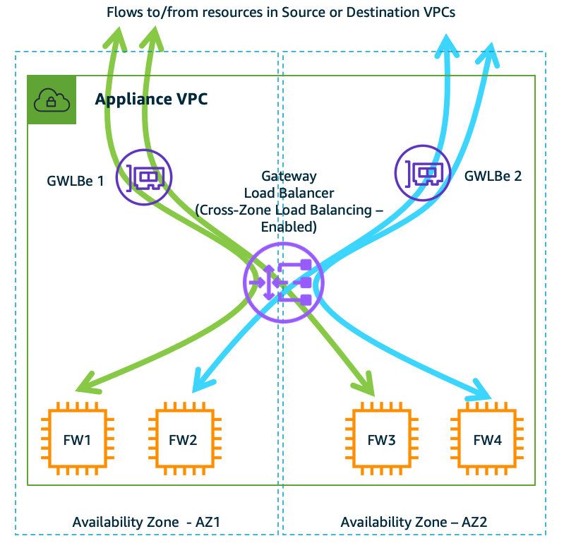
Figure 3: Typical deployment diagram of firewall with GWLB demonstrating how flows are distributed when cross-zone load balancing is enabled (disabled by default).
4. Understand appliance and AZ failure scenarios
The availability of firewall service can be impacted by two events: firewall failure or AZ failure. Like other AWS load balancers (Classic Load Balancer (CLB), Application Load Balancer (ALB), and Network Load Balancer (NLB)), GWLB is a regional service that runs in a VPC and is resilient to AZ failures. However, since GWLB Endpoint is an AZ resource, customers must create GWLB Endpoint in more than one AZ (see figure 3 above shown as GWLBe). And, unlike other load balancers, GWLB behaves differently in terms of flow management when such failure events occur (see table 1 below for summary).
Existing flows – When a target fails, load balancers like ALB and NLB terminate the existing flow/sessions and send a reset signal. However, because GWLB is a transparent bump-in-the-wire device, it works in a fail-open mode. That means the existing flows, being stateful in nature, continue to be associated with the failed target until they timeout or reset by the client. Refer to the recent enhancement made in AWS Gateway Load Balancer Target Failover for Existing Flows feature.
New flows – Based on the health check configuration (interval and threshold), once a target is flagged as unhealthy, GWLB adds up to 50-60 seconds of delay before it re-routes new flows to healthy targets. The minimum duration to start re-routing new flow is up to 70 seconds. It is a sum of 20 seconds for health checks (Min. Interval: 10s, Min. threshold: 2) and 50 seconds for GWLB backend to detect and re-route.
| Failure scenario | Cross-zone Load balancing | Existing flows | New flows |
| One of the FW fails in the AZ | Disabled | Timeout or need reset from client | Sent to healthy targets in the same AZ |
| One of the FW fails in the AZ | Enabled | Timeout or need reset from client | Sent to healthy targets in the same or across AZs |
| All of the FWs fail in the AZ | Disabled | Timeout or dropped until at least one target is restored | Timeout or dropped until at least one target is restored |
| All of the FWs fail in the AZ | Enabled | Timeout or need reset from client | Sent to healthy targets across AZs |
| One of the AZ fails in an AWS Region | Disabled or Enabled | Flows going through other AZs are not impacted | Flows going through other AZs are not impacted |
Table 1: The table above summarizes various failure scenarios with existing and new flows on an GWLB
The overall impact of the failure events on the existing or new flows depends on number of firewall instances serving those flows. For example, if you have 10 firewalls serving and if 1 firewall goes down, it impacts 10% of the flows up to 70 seconds.
5. Choose one-arm or two-arm firewall deployment modes for egress traffic inspection
GWLB supports two different models of firewall deployment (see figures 5a and 5b below) – one-arm with or two-arm where the firewall can also perform NAT.
One-arm mode: As shown in figure 5a below, the firewall is deployed in one-arm mode just for traffic inspection whereas NAT Gateway performs translation. This is the most common deployment method, and eliminates dependency on firewall supporting NAT functionality. Also, it increases performance of the firewall by offloading NAT to NAT Gateway.

Figure 5a: One-arm firewall deployment – The firewalls are just for traffic inspection whereas NAT Gateway is performing translation.
Two-arm mode: As shown in figure 5b below, the firewall is deployed in two-arm mode and performs both inspection as well as NAT. Some AWS partners provide firewall with NAT functionality. GWLB integrates seamlessly in such deployment mode. You don’t need to do any additional configuration changes in the GWLB. However, the firewall networking differs – one network interface is on the private subnet and the other is on public subnet. This mode requires software support from the firewall partner. Some of the GWLB partners (Palo Alto Networks, Valtix) support this feature, however consult with an AWS partner of your choice before using this mode.

Figure 5b: Two-arm FW deployment – The firewalls (in two-arm mode) perform both inspection and translation.
6. Choose one-arm or two-arm firewall deployment modes for SSL/TLS traffic inspection
GWLB acts as a transparent bump-in-the-wire device regardless of whether the traffic is encrypted or not. GWLB does not terminate the TLS flow or perform SSL offloading. Instead, it requires the firewall to perform decryption and deep packet inspection. In this use case too, GWLB supports two different firewall deployment modes (see figures 6a and 6b below).
One-arm mode: As shown in figure 6a below, the firewall is deployed in one-arm mode and GWLB passes through encrypted traffic. During the packet inspection process, the firewall decrypts and re-encrypts without changing the original 5-tuple (source/destination IP, source/destination port and protocol).

Figure 6a: The firewall, in one-arm mode, decrypts and re-encrypts before sending traffic out to Internet and vice-versa.
Two-arm mode: As shown in figure 6b below, the firewall is deployed in two-arm mode. The traffic enters firewall encrypted, which then gets decrypted and inspected before being sent to Internet or vice-versa. In this mode, the 5-tuple of two flows on the two arms of the firewalls do not have to match. Some of the GWLB partners that support this feature are Check Point, Palo Alto Networks, and Trend Micro. However, consult with an AWS partner of your choice before using this mode.

Figure 6b: The firewall, in two-arm mode, decrypts and encrypts before sending traffic out to Internet and vice-versa.
Conclusion
This post discussed best practices for Gateway Load Balancer that help you design and deploy third-party virtual appliances in your network architecture in a more robust, resilient, and scalable way. To get started on Gateway Load Balancer today, visit this page.
For more information about Gateway Load Balancer, you can refer to the following blogs:
- Gateway Load Balancer Deployment Patterns
- Centralized inspection architecture with Gateway Load Balancer and AWS Transit Gateway
- Scaling network traffic inspection using Gateway Load Balancer
If you have feedback or questions about this post, please start a new thread in Amazon Elastic Compute Cloud (EC2) forum or contact AWS Support.
An update was made on March 4, 2023: Expanded the behavior of idle timeout to address TCP flow and UDP packets. Referenced price reduction announcement for inter-az charges. Referenced enhancement made in target failover of the existing flows in GWLB.
An update was made on September 16, 2024: Clarified that reverse flows from asymmetric traffic is disrupted by GWLB endpoints instead of firewall instances. Callout that GWLB TCP timeouts are now configurable ad added support for 2-tuples, 3-tuples, and 5-tuples value to define flows.

Rohit Aswani
Rohit is a Specialist Solutions Architect focussed on Networking at AWS, where he helps customers build and design scalable, highly-available, secure, resilient and cost effective networks. He holds a MS in Telecommunication Systems Management from Northeastern University, specializing in Computer Networking.

Hrushikesh Gangur
Hrushi is a Sr. MLC Startups Solutions Architect at AWS with expertise in networking domain. He helps customer design and build resilient, scalable and cost-effective networks. Prior to joining AWS, Hrushi gained experience in OpenStack networking with NFV workloads.