Containers
Amazon EKS now supports Multus CNI
Today, Amazon Elastic Kubernetes Service (Amazon EKS) announced support for the Multus Container Network Interface (CNI) plugin, enabling customers to attach multiple network interfaces and apply advanced network configuration to Kubernetes-based applications. With Multus availability, communication service providers and other customers with unique networking requirements can configure their EKS clusters to run multi-homed Kubernetes pods that attach to multiple interfaces.
In this post, we’ll introduce the Multus CNI, cover applicable use cases, and walk through how to deploy and set up Multus CNI.
What is Multus CNI?
A CNI is the container network interface that provides an application programming interface to configure network interfaces in containers. Multus CNI is a container network interface plugin for Kubernetes that enables attaching multiple network interfaces to pods. In Kubernetes, each pod has only one network interface by default, other than local loopback. With Multus, you can create multi-homed pods that have multiple interfaces. Multus acts as ‘meta’ plugin that can call other CNI plugins to configure additional interfaces.
Multiple network interfaces for pods are useful in various use cases; examples include:
- Traffic splitting: Running network functions (NF) that require separation of control/management, and data/user plane network traffic to meet low latency Quality of Service (QoS) requirements.
- Performance: Additional interfaces often leverage specialized hardware specifications such as Single Root I/O Virtualization (SR-IOV) and Data Plane Development Kit (DPDK), which bypass the operating system kernel for increased bandwidth and network performance.
- Security: Supporting multi-tenant networks with strict traffic isolation requirements. Connecting multiple subnets to pods to meet compliance requirements.
Multi-homed pod
The Multus CNI plugin allows pods to have multiple interfaces in Kubernetes. The current version of EKS support for Multus bundles Amazon VPC CNI as the default delegate plugin (which is the only supported and validated default delegate plugin). The default delegate plugin configures the primary network interface (eth0) for pods to enable Kubernetes control plane traffic, including the IP Address Management (IPAM) for the primary network interface for the pods.
Here’s an example of how multi-homed pods can work on AWS. The image below shows two pods with two network interfaces, eth0 and net1. In both cases, the Amazon VPC CNI manages the pod eth0 (default Multus delegate). Interface net1 is managed by Multus via the ipvlan CNI plugin for pod1, which handles the user plane (eg: voice, video) traffic separated from the k8 control plane traffic. Where as pod2 net1 gets connected to the host elastic network interface through the host-device CNI plugin, and enables DPDK to accelerate the packet processing.

Let’s now look at how to set up a Multus CNI on an Amazon EKS cluster. We will demonstrate traffic splitting scenario with simple ping test across two sample applications. We will set up ipvlan CNI for managing secondary interface for pods. The ping test will be performed for the network provided by ipvlan plugin and managed by Multus.
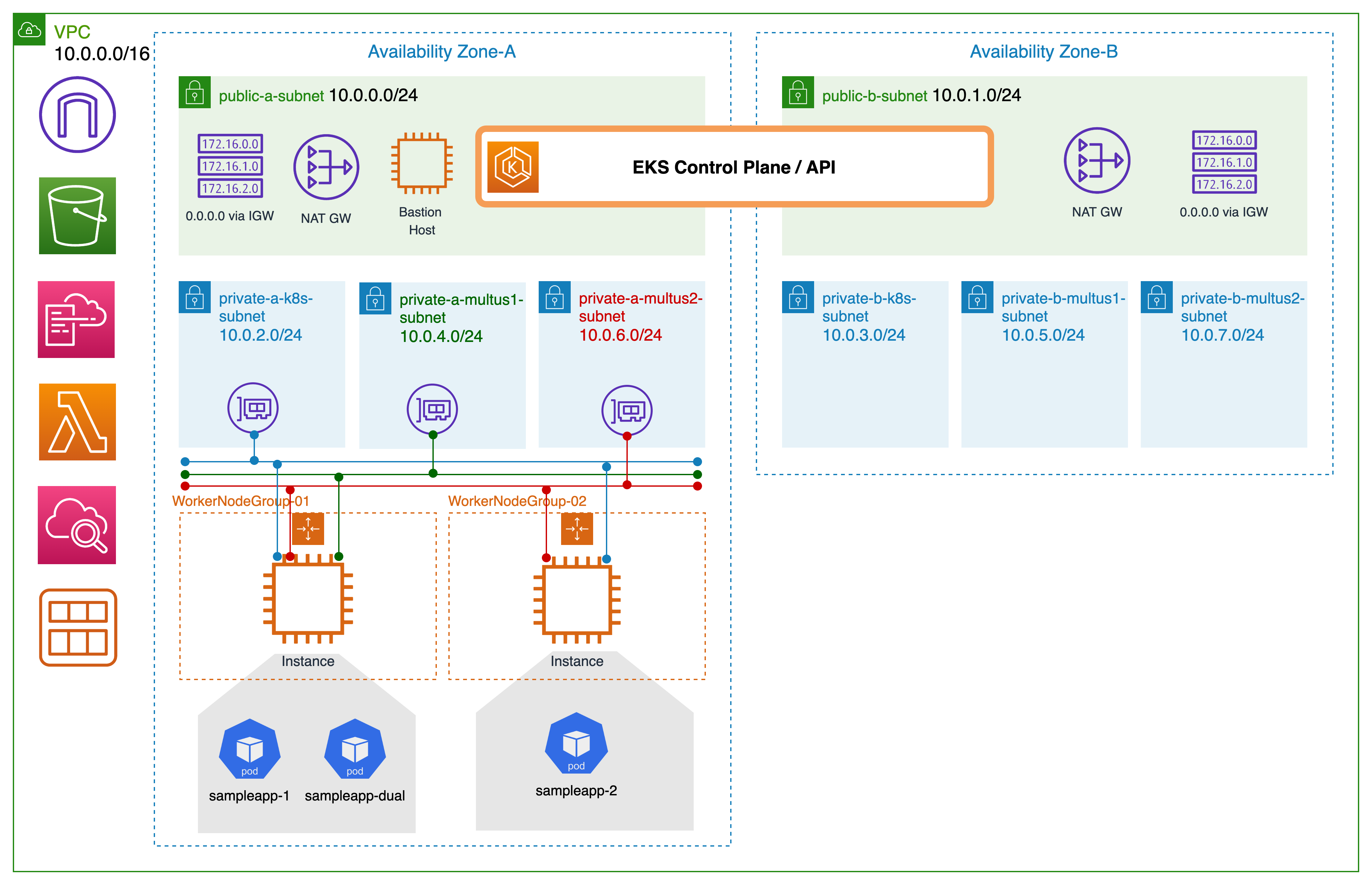
In this setup, we use CloudFormation templates to create the infrastructure, an EKS cluster, and a self-managed node group. The infrastructure template provisions Amazon Virtual Private Cloud (VPC), public and private subnets for clusters and Multus, and a bastion host to perform EKS operations. The node template creates worker nodes with additional ENI’s attached to run multi-homed pods. The two AWS CloudFormation templates together create the following resources:
- The infra creation template
- VpcCidr: A VPC CIDR that will be used for the deployment.
- AvailabilityZones: Minimum of two availability zones as per EKS requirement.
- PublicSubnet1/2: These subnets will host the bastion host to run kubectl commands. Also, this will host the NAT-GW to provide internet access for the private subnets.
- PrivateSubnetAz1/2: Subnets for the EKS control-plane in AZ1 and AZ2.
- MultusSubnet1Az1/2: The first subnet that Multus will be used to create secondary interfaces in the sample pods.
- MultusSubnet2Az1/2: The second subnet that Multus will be used to create secondary interfaces in the sample pods.
- BastionInstance: The bastion host where we can run EKS cluster operations from (kubectl).
- EksCluster: EKS cluster that will run sample workloads.
- EKS worker node group creation template
- NodeGroup: Worker node group to run sample pods.
- LambdaAttachCNI: Lambda function for attaching additional Multus subnet networks to worker nodes.
- EventbridgeEventRule: CloudWatch Event Rule for monitoring instance scaling up and down to trigger Lambda hook to attach additional Elastic Network Interfaces (ENI) from Multus subnets to worker node groups.
Prerequisites
- An AWS account with admin privileges: For this blog, we will assume you already have an AWS account with admin privileges.
- Create an EC2 key pair using the AWS Management Console (the steps are mentioned in EC2 user guide).
- Command line tools: Mac/Linux users need to install the latest version of AWS CLI, aws-iam-authenticator, and git on their workstation. Whereas Windows users might want to Cloud9 environment in AWS and then install these CLIs inside their Cloud9 environment.
- To get started with the Multus install, clone the
eks-install-guide-for-multusgithub repository on your local workstation or Cloud9 instance. - Locate the
eks-install-guide-for-multus/cfn/templates/cfn/nodegroup/lambda_function.zipfile in the local folder where you recently cloned your repo. Navigate to S3 in the AWS Management Console and create a bucket namedeks-multus-cluster. Select the same AWS Region as the EKS cluster and leave the rest as default. Click ‘Upload’ on the newly formed bucket. Tap ‘Add files’. Uploadlambda_function.zip. The S3 bucket name will be used as one of the input parameters when running the CloudFormation of worker node group described in the ‘Provision Worker Node Groups’ section.
Step 1: Create VPC and EKS cluster
Run the CloudFormation for infrastructure creation
- Log in to the AWS Console with your admin privileges, and go to CloudFormation.
- Click on Create stack → With new resources (standard).
- Upload a template file and choose ‘
eks-install-guide-for-multus/cfn/templates/infra/eks-infra.yaml’ . - Enter stack name ‘
eks-multus-cluster’, the stack name will also be the EKS cluster name. - Select two availability zones from the drop down.
- Use default VPC CIDR (
10.0.0.0/16) block and subnet ranges. - Choose bastion instance type (default,
t3-mediumshould also be ok). - Choose the EC2 key pair name from the drop down.
- For this exercise, you may use the default AMI Id.
- Click on Next → I Acknowledge → Create Stack.
Wait for the CloudFormation stack to finish (CREATE COMPLETE). An Amazon VPC with two public and private EKS subnets, four Multus subnets (two per AZ), an EKS cluster, IGW, and NAT-GW are created. The stack also builds security groups for Multus subnets and control plane security groups.
Record EksCluster, EksControlSecurityGroup, PrivateSubnetAz1/2, MultusSubnet1/2Az1/2, MultusSecurityGroup, and VpcId from the CloudFormation console outputs for the stack named ‘eks-multus-cluster’. Also, record BastionPublicIp from infra stack outputs. You will need this IP in the next section.
Bastion host configuration
To connect to your bastion using SSH:
In a terminal window, use the ssh command to connect to the instance. Specify the path and file name of the private key (.pem), the public ip recorded from the previous step. To connect to your instance, enter the following command.
ssh -i /path/my-key-pair.pem ec2-user@BastionPublicIpYou will see a response like the following:
The authenticity of host 'ec2-198-51-100-1.compute-1.amazonaws.com (198-51-100-1)' can't be established.
ECDSA key fingerprint is l4UB/neBad9tvkgJf1QZWxheQmR59WgrgzEimCG6kZY.
Are you sure you want to continue connecting (yes/no)
Enter ‘Yes’.
To configure AWS CLI:
You can use temporary credentials to run AWS CLI commands linked with the admin profile. You will use your own keys (below keys will not work for your environment).
export AWS_ACCESS_KEY_ID=AKIAIOSFODNN7EXAMPLE
export AWS_SECRET_ACCESS_KEY=wJalrXUtnFEMI/K7MDENG/bPxRfiCYEX...
export AWS_DEFAULT_REGION=us-west-2
export AWS_SESSION_TOKEN=FJ9BrbSXgCN4XYxFin+QYXsG8L6+lMMkMIv9xwZC48UqpwII9P.....
Confirm credentials with below command.
aws sts get-caller-identityOutput:
To install and configure kubectl:
curl -o kubectl https://amazon-eks.s3-us-west-2.amazonaws.com/1.21.2/2021-07-05/bin/linux/amd64/kubectl
curl -o kubectl.sha256 https://amazon-eks.s3.us-west-2.amazonaws.com/1.21.2/2021-07-05/bin/linux/amd64/kubectl.sha256
openssl sha1 -sha256 kubectl
chmod +x ./kubectl
mkdir -p $HOME/bin && cp ./kubectl $HOME/bin/kubectl && export PATH=$PATH:$HOME/bin
echo 'export PATH=$PATH:$HOME/bin' >> ~/.bashrc
kubectl version —short —client
To create your kubeconfig file with the AWS CLI:
aws eks update-kubeconfig --name eks-multus-cluster
kubectl get svc
Output:
Step 2: Provision node group
As part of this step, we will create self-managed node group. This step requires the S3 bucket created under prerequisites as well as the infrastructure stack to be complete. Alternatively, open the infrastructure stack CloudFormation output console in a new tab. The node group stack will use these outputs.
Run the CloudFormation template for node group creation
- Log in to the AWS Management Console with your admin privileges and go to CloudFormation.
- Click on Create stack → With new resources (standard).
- Specify a template, and upload a template file.
- Choose the
eks-install-guide-for-multus/cfn/templates/node-group/eks-nodegroup-multus.yamlfile from your local repo location. - Specify Cluster name and ClusterControl Plane Security Group from previous stack creation
- Enter stack name
multus-cluster-ng01. - Enter
multus-cluster-ng01as the Node group name. - Specify 1 for node autoscaling group desired capacity, max, and min size.
- Choose c5.large for instance type and 20 for volume size.
- Use default Node ImageId SSM Param and leave blank to use default EKS AMI.
- Choose the EC2 key pair created under the prerequisites section.
- You can use the default parameters for bootstrap.
- Choose
vpc-eks-multus-clusterVPC Id. - Select EKS subnets where the workers will be created (
privateAz1-eks-multus-cluster). - Specify Multus subnets (
multus1Az1-eks-multus-cluster, multus2Az1-eks-multus-cluster). - Enter Multus security group,
eks-multus-cluster-MultusSecurityGroup* - Specify the lambda S3 bucket name as
eks-multus-clusterand the S3 key aslambda_function.zip. - Click on Next → I Acknowledge → Create Stack.
Wait for the CloudFormation stack to finish (CREATE COMPLETE). To attach ENIs from defined Multus subnets, the node group stack deploys AWS Lambda function and Amazon CloudWatch event rule. The stack launches EC2 instance with ENIs attached from Multus subnets along with tag no_manage: true. AWS VPC CNI will not manage ENI’s tagged no_manage: true. This is a must step for Multus to manage additional networks for pods.
Record NodeInstanceRole from the CloudFormation console outputs.
Apply K8s ConfigMap update
Log in to the bastion host where you can run kubectl commands.
Download, edit, and apply the AWS authenticator configuration map:
curl -o aws-auth-cm.yaml https://s3.us-west-2.amazonaws.com/amazon-eks/cloudformation/2020-10-29/aws-auth-cm.yamlOpen the file with your favorite text editor. Replace ‘rolearn’ with NodeInstanceRole (output from worker node groups CloudFormation stack) and save the file. Do not modify any other lines in this file.
apiVersion: v1
kind: ConfigMap
metadata:
  name: aws-auth
  namespace: kube-system
data:
  mapRoles: |
    - rolearn: arn:aws:iam::my-account:role/worker-nodegroup-01-NodeInstanceRole-1M3F6VK25IKB0
      username: system:node:{{EC2PrivateDNSName}}
      groups:
        - system:bootstrappers
        - system:nodes
Apply the configuration. This command may take a few minutes to finish.
kubectl apply -f aws-auth-cm.yamlWatch the status of your nodes and wait for them to reach the Ready status.
kubectl get nodes --watchStep 3: Install and configure Multus
Install Multus CNI using a daemonset
Log in to the bastion host where you can run kubectl commands.
Run the following command to download and install the Multus daemonset. This command configures AWS VPC CNI as the default delegate plugin for Multus CNI.
kubectl apply -f https://raw.githubusercontent.com/aws/amazon-vpc-cni-k8s/master/config/multus/v3.7.2-eksbuild.1/aws-k8s-multus.yamlValidate the deployment by running the following command. Each node should have one pod named kube-multus-ds.
kubectl get pods -n kube-systemCreating additional interfaces
Next, we’ll create configurations for each additional interface we add to pods. Multus provides a Custom Resource Definition (CRD) named NetworkAttachmentDefinition. We’ll use this CRD to construct additional interface settings.
Create ipvlan-conf-1
Use ipvlan CNI to configure an additional interface (from Multus subnet 10.0.4.0/24) for the pod. Apply configuration to the cluster.
cat <<EOF | kubectl apply -f -
apiVersion: "k8s.cni.cncf.io/v1"
kind: NetworkAttachmentDefinition
metadata:
  name: ipvlan-conf-1
spec:
  config: '{
      "cniVersion": "0.3.0",
      "type": "ipvlan",
      "master": "eth1",
      "mode": "l3",
      "ipam": {
        "type": "host-local",
        "subnet": "10.0.4.0/24",
        "rangeStart": "10.0.4.70",
        "rangeEnd": "10.0.4.80",
        "gateway": "10.0.4.1"
      }
    }'
EOF
Create ipvlan-conf-2
Create another ipvlan CNI for the second Multus subnet (10.0.6.0/24). Apply configuration to the cluster.
cat <<EOF | kubectl apply -f -
apiVersion: "k8s.cni.cncf.io/v1"
kind: NetworkAttachmentDefinition
metadata:
  name: ipvlan-conf-2
spec:
  config: '{
      "cniVersion": "0.3.0",
      "type": "ipvlan",
      "master": "eth2",
      "mode": "l3",
      "ipam": {
        "type": "host-local",
        "subnet": "10.0.6.0/24",
        "rangeStart": "10.0.6.70",
        "rangeEnd": "10.0.6.80",
        "gateway": "10.0.6.1"
      }
    }'
EOF
Validate the configurations by running following command.
kubectl describe network-attachment-definitionsTo learn more about the configuration choices and examples for network attachments, please refer to the Multus how-to-use guide.
Step 4: Deploy sample application
Deploy sample application with single ipvlan attachment
Log in to the bastion host where you can run kubectl commands.
Create a sample application sampleapp-1 with network annotation we created in the previous step.
cat <<EOF | kubectl apply -f -
apiVersion: v1
kind: Pod
metadata:
  name: sampleapp-1
  annotations:
      k8s.v1.cni.cncf.io/networks: ipvlan-conf-1
spec:
  containers:
  - name: multitool
    command: ["sh", "-c", "trap : TERM INT; sleep infinity & wait"]
    image: praqma/network-multitool
EOF
Verify the pods network with the following command.
$ kubectl exec -it sampleapp-1 -- ip -d address1: lo: <LOOPBACK,UP,LOWER_UP> mtu 65536 qdisc noqueue state UNKNOWN group default qlen 1000
link/loopback 00:00:00:00:00:00 brd 00:00:00:00:00:00 promiscuity 0 minmtu 0 maxmtu 0 numtxqueues 1 numrxqueues 1 gso_max_size 65536 gso_max_segs 65535
inet 127.0.0.1/8 scope host lo
valid_lft forever preferred_lft forever
3: eth0@if7: <BROADCAST,MULTICAST,UP,LOWER_UP> mtu 9001 qdisc noqueue state UP group default
link/ether 82:62:21:8a:b5:98 brd ff:ff:ff:ff:ff:ff link-netnsid 0 promiscuity 0 minmtu 68 maxmtu 65535
veth numtxqueues 1 numrxqueues 1 gso_max_size 65536 gso_max_segs 65535
inet 10.0.2.215/32 scope global eth0
valid_lft forever preferred_lft forever
4: *net1@eth0*: <BROADCAST,MULTICAST,NOARP,UP,LOWER_UP> mtu 1500 qdisc noqueue state UNKNOWN group default
link/ether 06:e4:d4:62:f4:6d brd ff:ff:ff:ff:ff:ff promiscuity 0 minmtu 68 maxmtu 65535
ipvlan mode l3 bridge numtxqueues 1 numrxqueues 1 gso_max_size 65536 gso_max_segs 65535
inet 10.0.4.70/24 brd 10.0.4.255 scope global net1
valid_lft forever preferred_lft foreverAWS VPC CNI manages interface eth0, whereas ipvlan CNI manages interface net1 via Multus network attachment definition (ipvlan-conf-1).
Deploy sample application with dual ipvlan attachment
Create a sample application (sampleapp-dual) with dual network annotations ipvlan-conf-1 and ipvlan-conf-2.
cat <<EOF | kubectl apply -f -
apiVersion: v1
kind: Pod
metadata:
  name: sampleapp-dual
  annotations:
      k8s.v1.cni.cncf.io/networks: ipvlan-conf-1, ipvlan-conf-2
spec:
  containers:
  - name: multitool
    command: ["sh", "-c", "trap : TERM INT; sleep infinity & wait"]
    image: praqma/network-multitool
EOF
Verify the pod network with following command.
$ kubectl exec -it sampleapp-dual -- ip -d address
1: lo: <LOOPBACK,UP,LOWER_UP> mtu 65536 qdisc noqueue state UNKNOWN qlen 1000
    link/loopback 00:00:00:00:00:00 brd 00:00:00:00:00:00 promiscuity 0
    inet 127.0.0.1/8 scope host lo
       valid_lft forever preferred_lft forever
3: eth0@if15: <BROADCAST,MULTICAST,UP,LOWER_UP> mtu 9001 qdisc noqueue state UP
    link/ether f6:45:bf:ea:22:06 brd ff:ff:ff:ff:ff:ff link-netnsid 0 promiscuity 0
    veth
    inet 10.0.2.208/32 scope global eth0
       valid_lft forever preferred_lft forever
4: *net1@eth0*: <BROADCAST,MULTICAST,NOARP,UP,LOWER_UP> mtu 1500 qdisc noqueue state UNKNOWN
    link/ether 06:e4:d4:62:f4:6d brd ff:ff:ff:ff:ff:ff promiscuity 0
    ipvlan
    inet 10.0.4.76/24 brd 10.0.4.255 scope global net1
       valid_lft forever preferred_lft forever
5: *net2@net1*: <BROADCAST,MULTICAST,NOARP,UP,LOWER_UP> mtu 1500 qdisc noqueue state UNKNOWN
    link/ether 06:c2:b5:a5:08:c5 brd ff:ff:ff:ff:ff:ff promiscuity 0
    ipvlan
    inet 10.0.6.55/24 brd 10.0.6.255 scope global net2
       valid_lft forever preferred_lft forever
Test the connectivity across pods for Multus interfaces.
$ kubectl exec -it sampleapp-dual -- ping -I net1 <sampleapp-net1-ipaddress>
PING 10.0.4.77 (10.0.4.77) from 10.0.4.76 net1: 56(84) bytes of data.
64 bytes from 10.0.4.77: icmp_seq=1 ttl=255 time=0.034 ms
64 bytes from 10.0.4.77: icmp_seq=2 ttl=255 time=0.025 ms
64 bytes from 10.0.4.77: icmp_seq=3 ttl=255 time=0.023 ms
64 bytes from 10.0.4.77: icmp_seq=4 ttl=255 time=0.028 ms
Congratulations on the successful deployment of Multus CNI and running sample applications. You can refer to the Multus quick-start-guide for complete annotation options available for pods.
Cleanup
To avoid incurring future charges, you can delete all resources created using the CloudFormation service. Log in to the AWS Management Console, navigate to CloudFormation, and delete stacks (in the order of worker-node stack and infra stack) one by one.
Conclusion
In this blog post, we covered Multus CNI and its possible use cases. We also created an Amazon EKS cluster using Multus CNI and configured additional network definitions for sample pods to show traffic splitting.
This standardized process can be further automated with the use of AWS Cloud Development Kit (CDK) and AWS CodePipeline, or with third-party tools and an orchestrator through the API integration. Please refer to the aws-samples Git repo for CDK examples. Also, visit Amazon EKS user guide for Multus install instructions and for any recent product improvements.
Please note that the current support for Multus CNI does not include native configuration support for the pods secondary network interface, or other higher-order interfaces. This includes the IPAM for the Multus managed interfaces on the worker node (ENI’s tagged with no_manage: true) and the CNI driver and configuration associated with the higher order pod interfaces. While we continue to evolve the Multus experience for EKS customers, please provide feedback and suggest new features on the AWS Containers Roadmap available on GitHub.
For additional information, check out this blog post on how to construct a 5G mobile core network using Open5gs and Amazon EKS using Multus CNI.