AWS for Industries
LTE and 5G Data Network Breakout Designs on AWS
When Communication Service Providers (CSP) deploy Long Term Evolution (LTE) or 5G network functions on AWS, they are presented with different options for user plane data network breakout through the SGi (for LTE) or N6 (for 5G) interface. 3GPP defines SGi Interface as the reference point between the Packet Data Network (PDN) Gateway – S-GW and P-GW and the data network. Furthermore, N6 is defined as the reference point between the User Plane Function (UPF) and the data network. PDN can be a public external (e.g., Internet) data network, private packet data network (e.g., VPN), or intra operator packet data network.
This post covers data network breakout options for LTE or 5G UPFs on AWS in a non-roaming scenario. The term UPF refers to nodes such as SGW-U, PGW-U, TDF-U, and UPF as mentioned on 3GPP TS 29.244. PGW-U will be referred to in this document as P-GW.
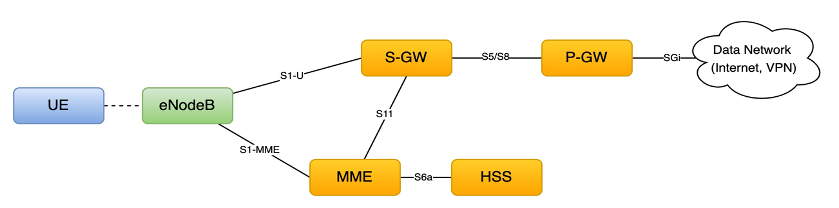
Figure 1: The SGi interface between the PDN Gateway, the P-GW, and data network (Internet) for LTE

Figure 2: The N6 interface between the UPF and data network (Internet) for a 5G
Solution Designs
LTE or 5G networks on AWS are operated by CSP as either Public Networks or Private Networks. Each network type can process different types of use cases: Enhanced Mobile Broad Band (eMBB) which usually relates with the Public Network’s consumer market, Ultra Reliable Low Latency Communications (URLLC) with strict requirements on latency like use cases related to autonomous vehicles, and Massive Machine Type Communications (mMTC) which involve supporting numerous devices sending data. Whatever the use case concerned, user plane traffic would involve exiting the P-GW or UPF to terminate to an application. There are different methods for reaching the data network when running network functions on AWS. We discuss the different breakout architectures using a 5G UPF function as reference.
Design 1: User plane breakout to public data network (e.g., Internet) via AWS Internet Gateway

Design 2: User plane breakout to public data network (e.g., Internet) via CSP’s on- premises network

This design shows N6 traffic routed back to an on-premises network. This approach hairpins user plane traffic to and from the UPF located on AWS. CSP using this type of architecture can continue to leverage their existing ISP connection to the internet or their private connections toward their enterprise customers. The VPC routing table for the N6 ENI subnet has the AWS Transit Gateway as the next hop for Internet traffic destinations. On the Transit Gateway, N6 data network traffic will be routed back to the N6 Virtual Routing and Forwarding (VRF) segment to reach on-premises.
Design 3: User plane breakout to private data network via Amazon Site-to-Site VPN
![]()
The previous architecture is typical for private network use cases where N6 traffic from the UPF terminates toward a third-party location via a secure VPN connection using AWS Site-to-Site VPN or a VPN appliance. The AWS Site-to-Site VPN service can be established using virtual private gateway or a Transit Gateway on the AWS side. More details on setting up Site-to-Site VPN can be found here. Bandwidth capacity of a single VPN connection of an AWS Site-to-Site VPN should be taken into account, which is 1.25Gbps. However, equal Cost Multi-path (ECMP) of multiple VPN tunnels can increase the overall bandwidth traffic required.
Design 4: User plane breakout to private data network on AWS via VPC Peering

The previous architecture is also typical for private network use cases where the 5G network functions and the use case application both run on AWS on each of their own VPCs. The two VPCs are interconnected using VPC peering. A VPC peering connection is a networking connection between two VPCs that enable traffic routing between them using private IPv4 addresses or IPv6 addresses. Instances or workers in either VPC can communicate with each other as if they are within the same network. When N3 traffic arrives from on-premises to the UPF on AWS, the UPF will do an NAT to translate the UEIP to the UPF ENI IP before sending out to the N6 interface. N6 data network traffic from the UPF is routed toward the application VPC using VPC peering as the next hop. Fully Qualified Domain Name (FQDN) application addresses are resolved by associating the network function VPC with an Amazon Route53 private hosted zone of the application VPC.
Design 5: User plane breakout to private data network on AWS via Transit Gateway

The architecture above is another typical use case for private networks. The 5G network functions and the use case application both run on AWS on their own VPCs. The two VPCs are interconnected using a Transit Gateway via VPC attachment. More details on VPC attachment can be found here. The N6 data network traffic from the UPF is routed toward the application via Transit Gateway as the next hop. FQDN application addresses are resolved by associating the network function VPC with a Route53 private hosted zone of the application VPC. Unlike VPC peering, Transit Gateway allows transitive routing.
Design 6: User plane breakout to private data network on AWS using subnet sharing via AWS Resource Access Manager

The previous architecture is another private network use case where N6 data network traffic from the UPF, which runs on an account, is sent to an application running on another account. Both the N6 interface of the UPF and application interface are sitting on the same subnet. Subnet sharing is made possible using AWS Resource Access Manager (AWS RAM) by creating a resource share. The VPC owner, the network function VPC, shares a subnet to the application account. Once shared, the application account can access the subnet and launch VPC resources. More on subnet sharing can be found here.
Conclusion
There are multiple designs for how LTE or 5G user plane traffic can breakout to the internet or to an application for a non-roaming scenario. AWS offers various services that enable CSP to send SGi or N6 traffic toward an application for both public and private network use cases. In choosing an architecture design, factors like latency, application entry point or access point, and use case should be considered. Visit AWS for Telecom to read more.