AWS for M&E Blog
Part 2: Working with SMPTE ST 2110 on the AWS Elemental Live Appliance
This multi-post series is a dive deep into the Society of Motion Picture and Television Engineers (SMPTE) ST 2110 suite of standards. The series explores the reasons customers transition from Serial Digital Interface (SDI) infrastructure to IP. It also looks at the trade-offs to consider when making the switch, and best practices to use AWS Elemental Live with SMPTE ST 2110.
PART 1: Background and key benefits of SMPTE ST 2110 on AWS Elemental Live
PART 2: Working with SMPTE ST 2110 on the AWS Elemental Live Appliance (this post)
PART 3: Simplifying SMPTE ST 2110 Management with NMOS
AWS Elemental Live appliances now support Society of Motion Picture and Television Engineers (SMPTE) ST 2110 for both inputs and outputs. This post walks through some of the necessary configurations and showcases sample workflows. This post assumes you have a basic familiarity with the AWS Elemental Live user interface and the SSH protocol.
LIVE 2110 SUPPORT OVERVIEW
Here is brief summary of the SMPTE ST 2110 capabilities that are currently supported in the AWS Elemental Live appliance.
2110 input:
- Standard Definition (SD), High Definition (HD) and 4K progressive and interlaced video sources (2110-20)
- Pulse-code modulation (PCM) (2110-30) and AC3/EAC3 (2110-31)
- 608/708 captions, teletext, and SCTE-35 (2110-40)
2110 output:
- SD, HD, and 4K progressive and interlaced video sources (2110-20)
- 2022-7 redundant outputs
- PCM (2110-30) and AC3/EAC3 (2110-31)
- 608/708 captions (2110-40)
- SCTE-35 to SCTE-104 conversion
- High-dynamic-range (HDR) support: HDR10, HLG2020
- PTP timing (Precision Time Protocol)
REQUIREMENTS
- 2.19.3 or newer software build (work with your account manager or visit the AWS Management Console to get the latest software build)
- SMPTE ST 2110 is supported on the newest models of Elemental Live L800 series that include the 25 GbE PCIe cards.
- In the Settings >> Network Settings >> Network Devices section of the Live console, enable SMPTE 2110 on the ethX port you want to use, and restart the Elemental service. The following image shows the eth4 port enabled for SMPTE 2110. The eth5 can also be used, but the other four ports are not compatible, as they are not 25 GbE ports.
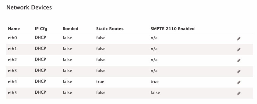
Network Devices Configuration in Elemental Live
SMPTE 2110 Enabled check box is checked
CONFIGURING 2110 INPUTS
Now I walk through the process to set up a 2110 input to the Live appliance. There are only a few items you need to ensure are in place. First, select the Input Type “SMPTE 2110 Input“. Naming the input and including an Ancillary SDP URI is optional. Since the information about the flows is controlled by the SDP file, all the Live appliance needs to know is where to access the SDP files.
NOTE: To ensure that your Live appliance can access the SDP files, you can use cURL from the node after you’ve SSH’d into the machine. For example:
curl http://10.12.132.24/emsfp/node/v1/sdp/76ff3bde-ef86-4218-8c5a-40a36ba0f05c
The preceding cURL responds with the contents of the video SDP, which tell the Live appliance how to properly decode the feed:
v=0
o=- 1443716955 1443716955 IN IP4 10.12.132.24
s=emsfp-A0-F0-5C 0-0-0
t=0 0
m=video 20000 RTP/AVP 96
c=IN IP4 238.132.24.101/64
a=source-filter: incl IN IP4 238.132.24.101 10.12.132.24
a=rtpmap:96 raw/90000
a=fmtp:96 sampling=YCbCr-4:2:2; width=1920; height=1080; exactframerate=50; depth=10; TCS=SDR; colorimetry=BT709; PM=2110GPM; SSN=ST2110-20:2017; TP=2110TPN;
a=mediaclk:direct=0
a=ts-refclk:ptp=IEEE1588-2008:00-02-c5-ff-fe-1b-9f-11:127
The audio SDP in this example looks like this:
v=0
o=- 1443716955 1443716955 IN IP4 10.12.132.24
s=emsfp-A0-F0-5C 0-1-0
t=0 0
m=audio 20000 RTP/AVP 97
c=IN IP4 238.132.24.102/64
a=source-filter: incl IN IP4 238.132.24.102 10.12.132.24
a=rtpmap:97 L24/48000/2
a=mediaclk:direct=0 rate=48000
a=framecount:48
a=ptime:1
a=ts-refclk:ptp=IEEE1588-2008:00-02-c5-ff-fe-1b-9f-11:127
This specific example originates from an AJA Ki Pro Ultra Plus to play out Apple ProRes content via 3G-SDI. It feeds into an Embrionix encapsulator added to the network switch, generating the 2110 flows pushed to our multicast network.
The following image shows the proper setup of a 2110 input. It pulls the first essence flow referenced in the SDP file for each of the Video, Audio and Ancillary data over eth4. The Media Index of “0” signifies the first essence in the SDP. Since you can include multiple essence flows in one SDP file, it is often used if building redundancy with multiple input sources. Note that you have manual control of these flows, so leave the NMOS Control unchecked. I discuss NMOS in more depth in part 3 of this series.
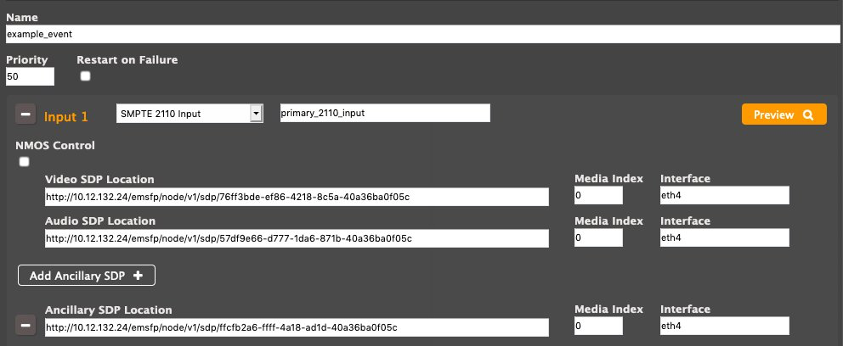
SMPTE 2110 Input is selected with Video and Audio SDPs added to the configuration
Finally, to confirm that your input is valid and functional, click the Preview button. This starts up the flows and shows you a video preview window and a MediaInfo dump, shown in the following image.
Notice the new setting – stream_uri: smpte2110://1
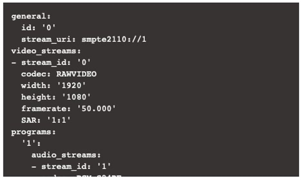
MediaInfo showing the 2110 Input
It’s important to get the settings correct to prevent issues with your flows. This is not isolated to 2110; it also applies to SDI inputs. Depending on the Live model and resolutions of your inputs, you may experience dropped frames when generating outputs. This is more prevalent with UHD inputs and outputs due to the sheer bitrate. There are two key places to make adjustments. First, under Additional Global Configuration, adjust the number of frames in the Input Buffer Size. This uses more memory, but prevents dropped frames at the cost of latency. The following image shows the default settings and the buffer size of 60 frames.
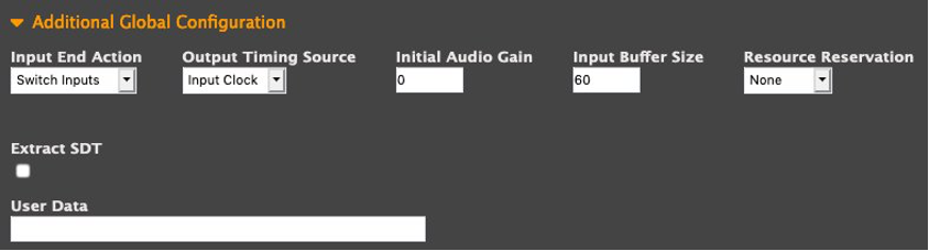
Input Buffer Size is set to 60 frames
Second, the Density vs. Quality setting can be adjusted towards density when dealing with AVC/HEVC outputs. The recommended settings are “-1” for AVC, and “.5” for HEVC.
It’s also important to never duplicate the usage of 2110 inputs on the same machine. Each source should be used only once, just like you would with SDI inputs. If you’re still experiencing issues, ensure that your network is not being overloaded.
CONFIGURING 2110 OUTPUTS
Precision Time Protocol (PTP) is required for 2110 outputs and must be configured before you start your Live events. Since Network Time Protocol (NTP) is used by default, and cannot be used with PTP, the NTP, the service must be disabled. If Live can’t communicate with, or receive updates from, the PTP leader clock, it throws a new alarm. After configuring the PTP leader clock on your network, select Enable PTP and click Save from the Hostname, DNS, and Timing Server section of your Settings>>Network tab.
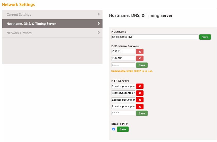
Enable PTP check box is checked
To generate a 2110 signal out of a Live appliance, first create a 2110 Output Group. Then create an output for every SMPTE 2110 video, audio, or ancillary stream desired. In this example, I generate a video flow and an audio flow.
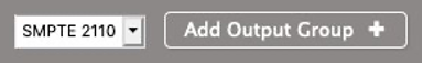
SMPTE 2110 Output is Selected in the Drop Down for Outputs Groups
Each flow has only one component, so all others need to be removed from the output. In this example, I am going to remove the audio from the first output, and the video from the second output. The order of the “Streams” is irrelevant to the functionality since they are indeed independent. See the following image, which shows the four main changes required.
- Add an output resolution
- Video Codec is Uncompressed
- FourCC is set to s210
- Audio Codec is PCM
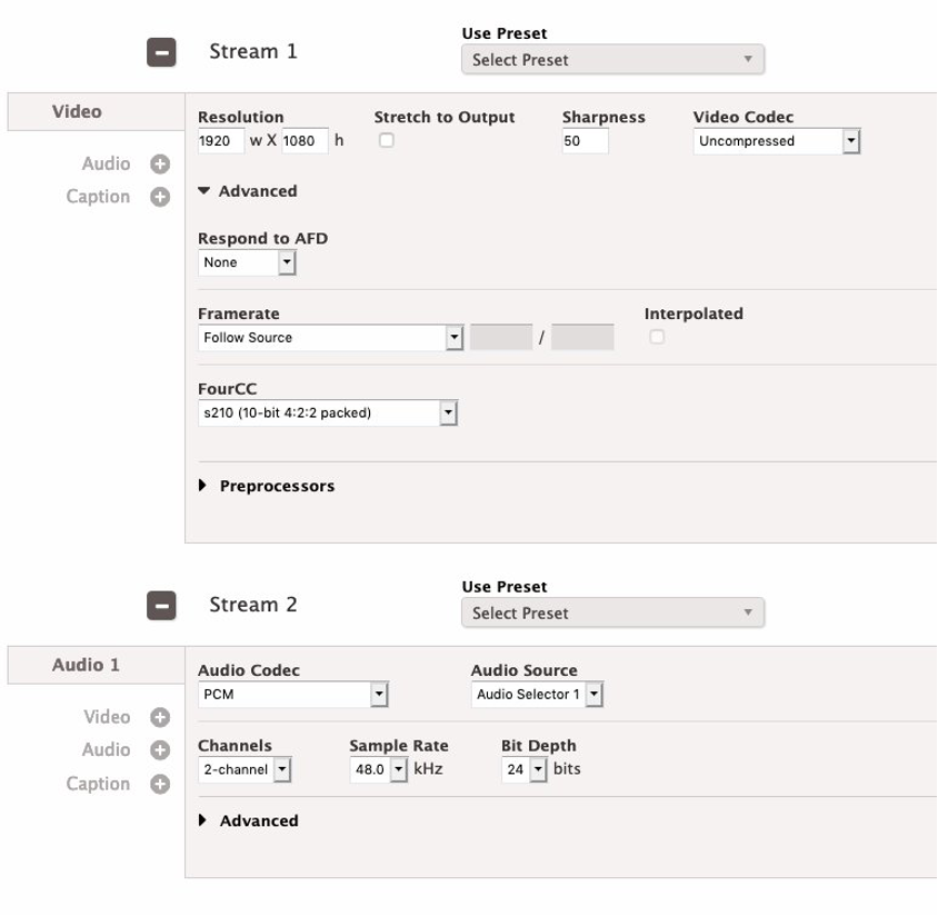
Stream Settings with the previously mentioned changes applied
Now configure the RTP addresses on your network where the flows are pushed to. The “Primary Destination” and “Interface” is required and the “Secondary Destination” and “Interface” can be used for a SMPTE 2022-7 redundant output. The outputs can be Unicast or Multicast, but requires RTP per the 2110 specification. You need to be sure to use a 25GbE interface that is enabled for SMPTE 2110. This example uses eth4. Depending on your 2110 receiver capabilities, you can select a Packet Time of 1000 or 125.
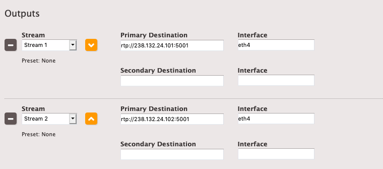
Outputs shown with RTP URIs included
You can manually create the SDP files and store them locally on the Live appliance. If you place the SDP in, for example, /opt/elemental_se/web/public/2110_video.sdp it is available on http://localhost/2110_video.sdp. Here you can test another event on the same machine using this as the 2110 input. Other machines on your network could access that SDP file using the local IP Address instead, such as http://10.12.132.24/2110_video.sdp.
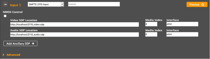
Input shown with localhost addresses for video and audio SDPs
Alternatively, you can rely on the SDP file that is generated by the Live appliance. You can find the SDP files appear in:
/opt/elemental_se/web/log/1000/<event_number>/*eme_.log
If you search for the string: “Writing SDP file to” you see a result that contains a path to your SDP, which you can download by copying the remainder of the string after “/opt/elemental_se/web/public”. The full example would be available at:
http://hostname/SmpteSt2110Output.LiveEvent_1.OutputGroup_output_group_1.video_185.sdp
I discuss this more in the next section, but if the output is NMOS managed, the SDP file would instead be located in:
http://hostname/sdp/SmpteSt2110Output.LiveEvent_1.OutputGroup_output_group_1.video_185.sdp
In this post, I walked through the setup for both input and output of 2110 flows while manually controlling the SDP configurations. I also discussed the importance of setting up PTP for 2110 outputs. In the next post, I look at simplifying this process with the use of an NMOS registry.