Networking & Content Delivery
Test Automation of multicast IoT devices at Doppelio using IGMP v2 and the AWS Transit Gateway
Context
IoT solutions today are both complex and business critical. At the same time, testing them thoroughly proves difficult because of the need to apply conditions of load, network, sensor behavior, and others. To address these, “Doppelio” – a SaaS-based IoT test automation solution was built as it helps alleviate IoT test limitations. It does so by spinning up virtual devices on-demand to simulate several conditions. A customer creates virtual devices – called Doppels, that behave like real devices. Doppels are controlled using our simulation engine to verify if IoT applications can handle different scenarios.
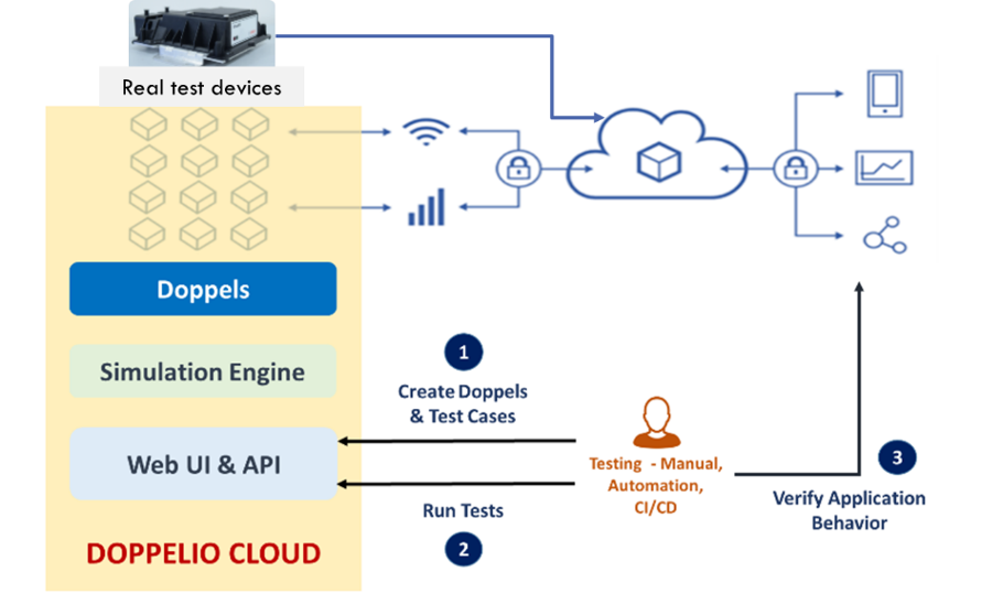
Figure 1 : IoT applications testing using virtual devices in Doppelio Cloud
Most IoT devices use typical application protocols like MQTT, HTTP, Web Sockets, or at times even raw TCP. All these protocols are supported by Doppelio solution that allows it to communicate with the customer hosted cloud applications.
The customer first sets up their device models, creates virtual devices – the Doppels – and then authors various tests to ramp-up load. This introduces network and data faults or various data patterns to validate behavior of their cloud applications under different conditions.
Recently, we had a requirement to simulate IoT devices that used multicast communication. Since we are hosted on AWS, our first question was whether AWS supported multicast. AWS Transit Gateway supports multicast natively, hence could leverage this capability in our setup.
Considering the availability of Internet Group Management Protocol (IGMP) Multicast on AWS Transit Gateway, we built the architecture on AWS. We also referred to the blog Integrating external multicast services with AWS where we saw reference architectures that met our hybrid multicast source and receiver requirements.
This post describes in detail how we went about building this architecture to enable multicast routing between AWS and on-premises.
Scenario
The scenario involved simulating a system akin to SIP devices (also known as VoIP phones) that could be used for group addressing using multicast audio. The devices could be used to join a conference call or to broadcast to a group of devices. The devices would be in a network with multicast routers. For group addressing, they would send streams to a specific multicast group which other devices would join. For a conference call, would be initiated by a person when they “dialed in” to their conference code.
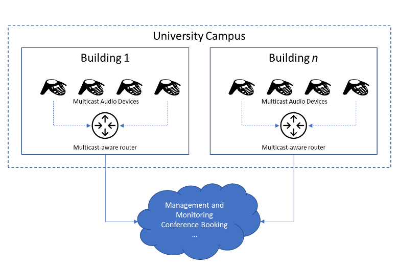
Figure 2 : Multiple audio devices communicating over multi-cast network
Doppelio was to be used to create these virtual SIP devices, communicating over multicast with each other, and with a cloud-based system for managing and monitoring them. Additionally, the intent was to simultaneously test with both real devices and Doppels. The overall picture would then look like:
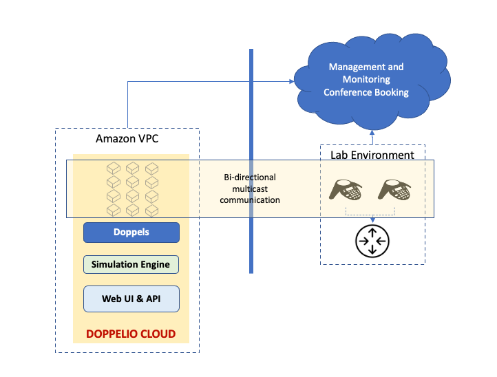
Figure 3 : Multicast testing with hybrid setup: Doppelio Cloud along with real devices
This posed multiple challenges that we needed to address:
- Multicast support was needed inside the Amazon Virtual Private Cloud (Amazon VPC) for virtual devices to communicate.
- Devices needed to be added / removed dynamically on-demand. This meant multicast groups cannot be static and must have full IGMP support – at least v2.
- Multicast required between real devices in remote lab environment and virtual devices in Amazon VPC.
Setting up multicast in AWS and on premises using Transit Gateway
The approach we took was to build architecture incrementally to eventually reach final state. The steps we considered were:
- Build multicast network within the VPC, using AWS Transit Gateway and dynamic multicast with IGMP v2. This was followed by verifying that Doppelio instances (in AWS) can send multicast traffic between themselves.
- Build connectivity between our VPC and the on-premises remote lab. This was done using AWS Transit Gateway Site-to-Site VPN underlay and GRE overlay.
- Site-to-Site IPsec Tunnel between AWS Transit Gateway and Customer Edge Device (represented as Customer Gateway inside AWS which is an on-premises CSR1000v)
- Provision a virtual router CSR1000v in private subnet and establish GRE Tunnel between it and customer edge device (on-premises also a CSR1000v)
- Enable Multicast routing on either side of the tunnel, configuring PIM (Protocol Independent Multicast) on both sides more details regarding this are given in the following sections
- Finally, verify successful multicast bi-directional traffic flows i.e. from the Doppels instances in VPC to the real lab device on-premises and vice versa.
Step 1: Build dynamic multicast in AWS using AWS Transit Gateway
Our first step was to look at the newly introduced support for IGMP v2 to see if we could use that for dynamic membership.
- Create a Transit Gateway with multicast support enabled, in a region that supports IGMP v2 (we used N. Virginia). Kindly refer to this link for the list of supported regions
- Create an attachment between this Transit Gateway and the VPC.
- Create a Transit Gateway Multicast Domain with IGMPv2 support enabled. Kindly refer to documentation for more details on creating a Transit Gateway Multicast domain with IGMPv2
- Set up receivers using EC2 instances with following considerations :
-
- We used Nitro instances (we used m5n instances) for all nodes. Kindly disable source/destination checks if you are using non-Ntro instances.
- On our Ubuntu machines, we set up a route for the multicast traffic:
sudo route add -net 224.0.0.0 netmask 240.0.0.0 ens5-
- Verify that the network interface type is correct for your instance by using ifconfig. ens5 is what we had for our instances.
- We forced the IGMP version on all the instances to v2:
echo “2” > /proc/sys/net/ipv4/conf/eth0/force_igmp_versionPlease note senders do not require any special configuration as above.
- Send/receive multicast traffic between instances
iperf -s -u -B 239.10.10.1 -i 1
In a couple of seconds, the Transit Gateway Multicast Group showed the receivers as members of the above group. After this, we used another instance as a source, by running iperf in client mode:
iperf -c 239.10.10.1 -u -T 32 -t 3 -i 1And with this, the traffic was reflected correctly on all receivers!
Step 2: Build connectivity between VPC and on premises lab
To enable private traffic flow between AWS and on-premises network, we need to establish network connectivity between these two sites. AWS offers different options to set up VPC connectivity e.g.,AWS Direct Connect, AWS Managed Site-to-Site VPN.
For this demonstration, we will be configuring 2 overlay tunnels as follows:
- Create Site-to-Site IPsec Tunnel between AWS Transit Gateway created in previous section and Customer Edge Device (represented as Customer Gateway inside AWS which is an on-premises CSR1000v)
- Once IPSec tunnel is UP, setup a GRE Tunnel between CSR1000v (virtual router in private subnet) and customer edge device (on-premises CSR1000v)
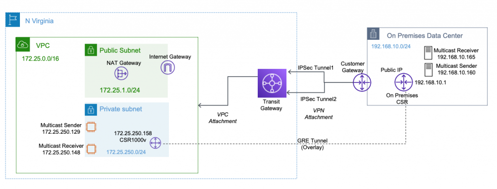
Figure 4 : Multicast setup on AWS and on premise using Transit Gateway
Configuration of both the tunnels is summarized below for easy reference of the readers.

Configuration of GRE tunnel between Amazon VPC and on premises
- Configure a Tunnel interface on the CSR router running on AWS
Loopback interface configuration (required for multicast to work over GRE)
Note: The GRE tunnel source can be a loopback, physical, or L3 EtherChannel interface. As a , we have configured loopback interface as tunnel source interface. For more details on configuring GRE tunnels kindly refer the link.
Kindly make sure for this loopback IP to be reachable from both the sites.
Loopback Interface along with static route to reach loopback IP address on the CSR router in the on-premises network
Tunnel interface configuration
- Configure the Tunnel interface on the Remote CSR running on on-premises.
Loopback interface configuration :
Static route to reach loopback IP address of the CSR router in AWS and Tunnel interface configuration :
Verify the Tunnel configuration by pinging the Remote IP address.
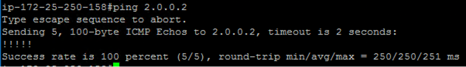
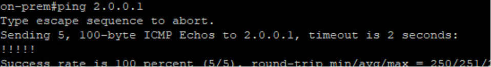
Figure 5 : Verify GRE tunnel configuration between AWS and On premise network
Step 3: Enable Multicast routing between VPC and on-prem lab
Now that we have successfully established a GRE tunnel between both the sides, it’s time to log in to both the CSRs and set up multicast routing and enable PIM on the relevant interfaces so that both the CSRs will start forwarding Join requests from receivers towards multicast sources.
Multicast routing should be configured on the first hop router (FHR), the rendezvous point (RP) and the last hop router (LHR) to support multicast over the GRE tunnel.
For more details on RP configuration kindly refer the following link.
We have configured the AWS side CSR as a RP router. 192.168.250.1 is the lookback interface configured on the CSR running inside Amazon VPC
Sample multicast configuration on the AWS side CSR
Sample multicast configuration on the On-Premises CSR.
Verify the multicast configuration
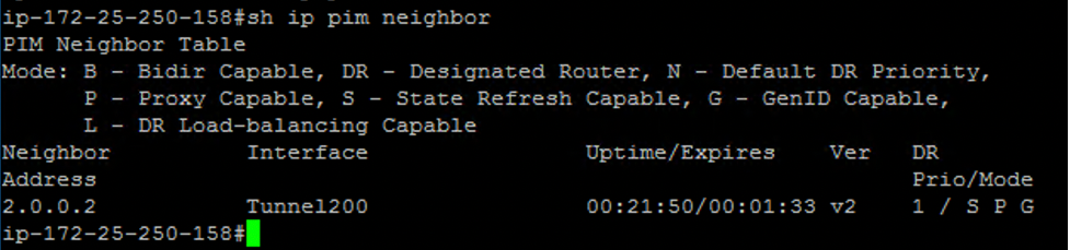
Figure 6 : PIM neighborship output from AWS CSR1000V instance
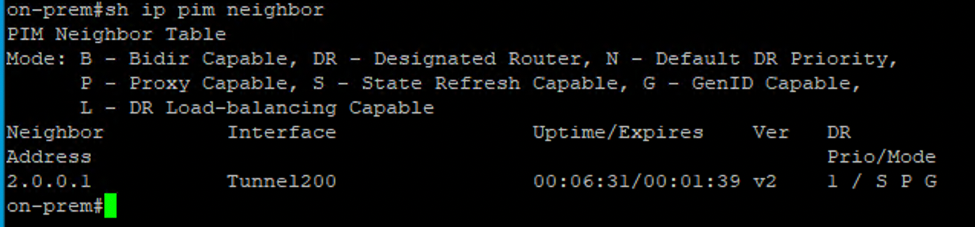
Figure 7: PIM neighborship output from AWS CSR1000V instance
Step 4: Verify Multicast Traffic flow
Once multicast setup was up, we used VLC Media Player/ Singlewire testing utility on Windows Ec2 instance to send /receive multicast traffic from AWS to on-premises and vice-versa.
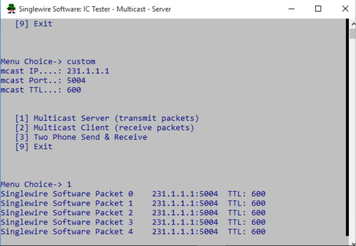
Figure 8: Multicast sender/server
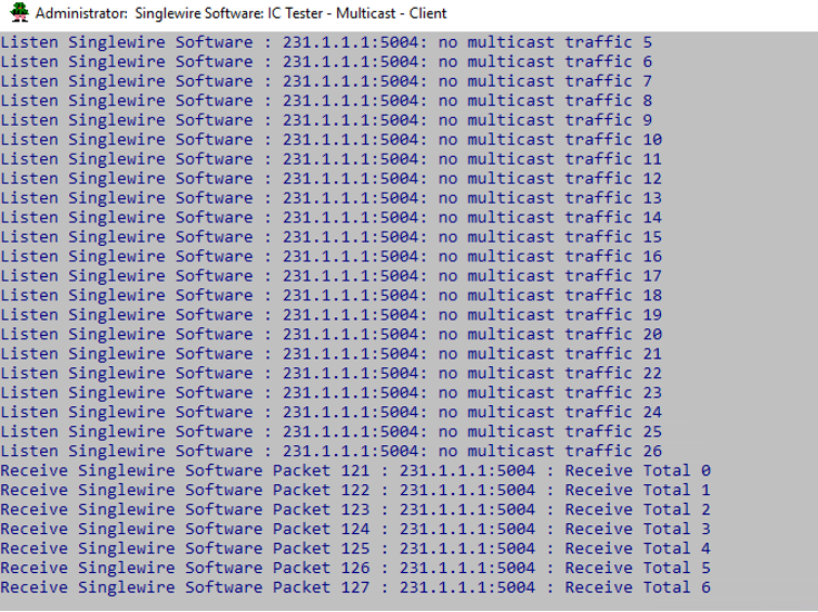
Figure 9: Multicast Receiver/Client
We then set up our Doppelio EC2 instances so that they had the same OS configuration as Step -1 above, and when we created our virtual devices the Doppels – on these instances, they were able to send and receive multicast traffic with on prem appliances.
Conclusion
IoT solutions are becoming more and more widespread and mission critical, and their testing is therefore essential. Devices are also evolving beyond simple point data sources to being rich multimedia capable entities, and the ability to interact with them using mechanisms such as multicast right from the cloud is an important element.
Multicast on transit gateways allows us to build advanced architectures to perform multicast routing on AWS.
The AWS support for IGMP is a key capability that customers can use in this area. It makes it easier for customers to scale up multicast workloads, while also simplifying the management of multicast group membership and network deployment.
Author bio
|
Srinivas Bhagavatula |
At Doppelio, we significantly leverage the IaaS and PaaS capability of AWS for our SaaS solution. I am a software architect and developer, and my day job is to make key technical decisions at Doppelio. |
|
Saravanan Mani |
Saravanan Mani is a Cloud Architect at Stovl Consulting. He works on designing and implementing cloud solutions for new age startups and large enterprise customers primarily focusing on SaaS, Cloud Native, containers, Kubernetes and Microservices based applications.
|
|
Vijay Jadhav |
Vijay Jadhav is a senior Cloud Architect at Stovl Consulting with 15+ years of overall IT experience. In recent years, focusing on designing innovative solutions for AWS customers and sharing knowledge with the other cloud enthusiasts |
|
Mahesh Beri |
Mahesh Beri is Enterprise Architect at Amazon Web Services. He works with large enterprise Financial Services customers in India to help accelerate their cloud adoption journey. |


Suggested tags: Transit Gateway, Multicast, IoT