The Internet of Things on AWS – Official Blog
Monitor and visualise building occupancy with AWS IoT Core, Amazon QuickSight and Raspberry Pi
Occupancy monitoring in buildings is a valuable tool across different industries. From healthcare to industrial, and from entertainment to retail, customers are looking for modern and scalable IoT solutions to make practical business decisions. For example, many exhibitions in public art museums employ an open-ended approach, where there is no clear starting or finishing point to the exhibition. The layout of an exhibition needs to take into consideration the way in which the viewers find their way through the exhibition contributes to the viewers’ engagement with the artwork. However, museums can vary the placement of the gallery based on the popularity and number of visitors. They can analyse occupancy data in near real-time and decide the particular gallery should be at the entrance of the building to gain more views or it is already popular and can be moved and grouped with other exhibitions.
This blog describes a simple solution that uses building occupancy data to monitor how space is being utilised. It shows how busy each sub-area of the building gets during different times of the day based on a motion sensor’s location. We place the physical device which consists of a Raspberry Pi with Passive InfraRed (PIR) sensor at the entrance. The PIR sensor allows one to sense the motion in direct proximity, (i.e., whether a human has moved in or out of the sensors range) and will generate the data which then will be connected to cloud native services for data storage, analysis and visualisation in near real-time.
Solution Overview
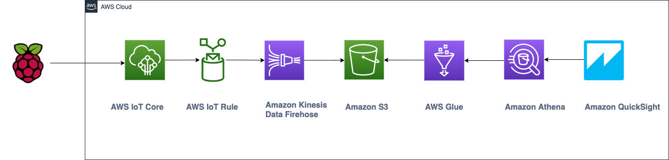
The diagram shows a high level architecture overview. The data is generated locally on the Raspberry Pi and published in JSON format to AWS IoT Core that easily and securely connects devices through the MQTT and HTTPS protocols. Rules Engine, a feature of AWS IoT Core, continuously processes incoming messages, enabling your devices to interact with other AWS services and streams IoT data into Amazon Kinesis Data Firehose. Kinesis Data Firehose allows you to capture and automatically load streaming data into Amazon S3. AWS Glue creates a data catalog with a table for Amazon Athena to query this data from Amazon S3 bucket. Amazon QuickSight, the cloud-powered business intelligence tool, connects to Amazon Athena to create a visualisation dashboard for further analysis.
Prerequisites
Minimum requirements:
- An AWS account.
- Raspberry Pi 4 Model B with a pre-installed Operating System SD card and a power cable.
- Passive InfraRed (PIR) sensor.
- Breadboard with female to female(F2F) and male to male (M2M) jumper wires, LED light and resistor.
During the process I use the headless connection type with third party software providers to access the Raspberry Pi, additionally you can access via SSH.
Step-by-step Implementation
Note: I use a stock Raspberry Pi 4 Model B. Figure 1 shows the Raspberry Pi mounted on a Black Case Box kit. This Box kit neatly packages the Pi and prevents damage, but is not necessary.
Figure 1 shows a Raspberry Pi with marked colours where the same-coloured wires will be connected with the sensor and a breadboard. I use the following pinout in Raspberry Pi:
- 5V power – marked as red
- GROUND – purple
- GPIO 4 (GPCLK0) – orange
- GPIO 17 – green
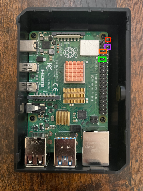 Figure 1: Raspberry Pi.
Figure 2 shows necessary components such as a breadboard, PIR sensor, a resistor, red LED light, 5 male-to-female and 1 female-to-female jumper wire cables.
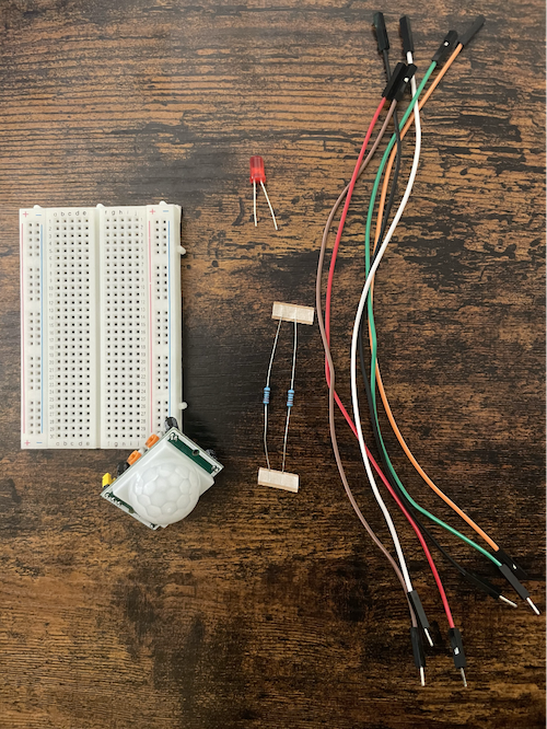
Figure 2: Necessary components.
Figure 3 demonstrates the breadboard marked with colours where the same coloured wires belong. Let’s look at them in more detail:
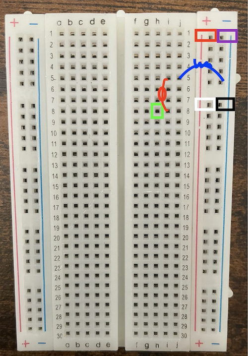
Figure 3: Breadboard with the wires, resistor and LED light diagram
- The blue curve indicates the resistor and the same-coloured jumper wire will be inserted into ‘5-’ and ‘5J’.
- The red LED light is shown as a red line with a circle on top. If you look at the LED light, you will see that it has two different tip lengths, the short part will be inserted into ‘I5’ and the long one into ‘I8’.
- The green square marked in ‘H8’ is used for the LED light to communicate with Raspberry Pi and LED light.
- The white and black squared ‘7+’ and ‘7-’ wires are connected with the PIR sensor, in particular to the GND and VCC pinout of the sensor.
- The red and purple squared ‘1+’ and ‘1-’ wires are connected with the coloured pins in Raspberry Pi, in particular to the 5V power and GROUND pinouts.
Figure 4 shows the Passive InfraRed (PIR) sensor with VCC, GND and OUT pinouts, where black, white and orange coloured jumper wires will be connected.
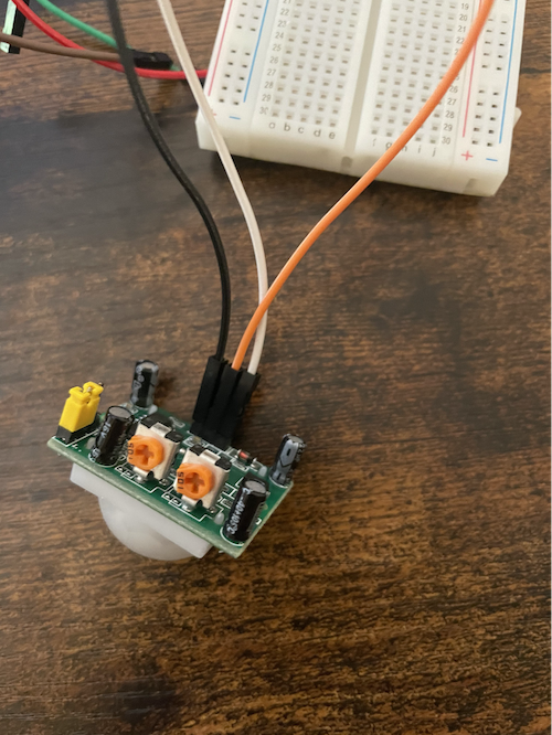
Figure 4: PIR sensor connected with the Raspberry Pi and the breadboard.
- The white and black wires on the PIR sensor are connected with the same colour marked pins in the breadboard, as seen in Figure 3.
- The orange wire is connected to the Raspberry Pi GPIO 4 (GPCLK0) pinout or as marked in orange colour, as seen in Figure 1.
Now, it’s time to connect the PIR sensor, the breadboard with the red LED light and the resistor, and Raspberry Pi with each other. If everything is connected correctly, the red LED light will turn on if any motion detected as seen in Figure 5, the code for which we will write up in later steps.
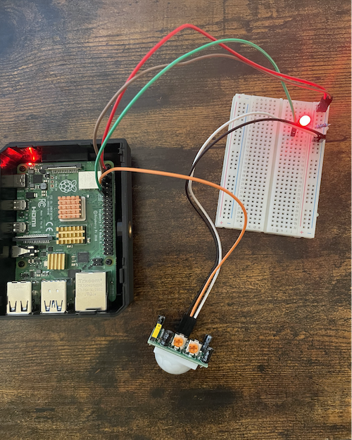
Figure 5: Mounting everything together on Raspberry Pi.
Once the physical construction is complete, we are ready to look into details on how to connect and send JSON motion detection data to AWS and save it securely.
The rest of the blog details 5 steps for publishing IoT data to the cloud and developing near real-time dashboards. The steps are briefly summarised and then described in further details below.
- How to connect a Raspberry Pi to AWS IoT Core
- How to stream JSON data to Amazon Kinesis Data Firehose and save to Amazon S3
- Create AWS Glue Data Catalog
- Configure Amazon Athena
- Visualise object movement with Amazon QuickSight dashboard in near real-time
Step 1. How to connect a Raspberry Pi to AWS IoT Core
In this section, I describe how to set up the PIR sensor that when motion is detected the red LED light turns on and we see a message “Motion Detected” on the Raspberry Pi. Next, we will need to connect our Raspberry Pi with AWS by registering it as a “thing”, creating a policy and certificates. In the end, we will see the motion messages transmitted to the cloud and saved securely for further analysis.
1.1 Start creating a policy in AWS IoT Core and we will attach this policy to our thing in the next step.
- Navigate to the AWS IoT Core console. In the navigation pane, choose Secure, Policies, Create a policy.
- For the Name give your policy a name.
- For Add statements choose Advanced mode and add the policy statement with your AWS region, account number and topic name as seen below. Please check this source for more policy examples.
- Select Create.
1.2 Create and download the AWS IoT Core device certificate
The Raspberry Pi requires an AWS IoT root CA (fetched by the install script), certificate, and a private key to authenticate with AWS IoT Core. Create a new certificate and attach the IoT policy deployed by the serverless application.
- Navigate to the AWS IoT Core console. In the navigation pane, choose Manage, Things, Register a Thing, Create a single thing.
- For the Name give your thing a name.
- For the rest leave it as default
- Select Next and Add a certificate for your thing
- Create a certificate with One-click certificate creation (recommended)
Once you followed the steps above and initiated the ‘one-click certificate creation’, you will see a message that the certificate is generated successfully, as seen below. Now, the certificates are available for download. Save these certificates securely as you will not have a second chance to download the same certificates.
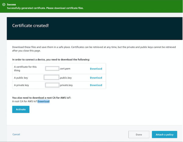
Having created a certificate, you need to do the following:
- Select Download “a certificate for this thing” and “a private key”. (Save these securely, as this is the only time you can download this certificate.)
- You also need to download a root CA for AWS IoT (right click on download and select on RSA 2048 bit key Amazon Root CA1, save as a file)
- Activate the Root CA for AWS IoT.
- Choose Attach a policy (that we created on step 1.1).
1.3 Download certificates and securely save it to your computer.
Now, we need to copy these certificates to Raspberry Pi, so that it understands where to connect and send the generated data. There are several options to connect with Raspberry Pi and copy over the files. I use the SFTP route and save the certificates in a safe folder in my Raspberry Pi from where I can reference in my code later.
1.4 Install AWS IoT Python SDK in the Pi and create a motion_detected.py file to write our python code
1. Open the terminal in the Raspberry Pi and install AWS IoT Python SDK:
2. Create a motion_detected.py file in the Raspberry Pi to write our Python script that will identify whether motion has been detected by the PIR sensor.
3. Copy and paste the python script below to motion_detected.py file:
Let’s examine the code above:
1. We import some directories from the Python library (LED, motion sensor, date and time, MQTTClient which was installed from AWSIoTPythonSDK)
2. We connect our Raspberry Pi to AWS IoT Core by setting up a name for MQTT client, such as “ClientID’” in my case it is myMQTTClient = AWSIoTMQTTClient(“ClientID”)
3. We create a loop to turn the LED light on/off upon movement detection.
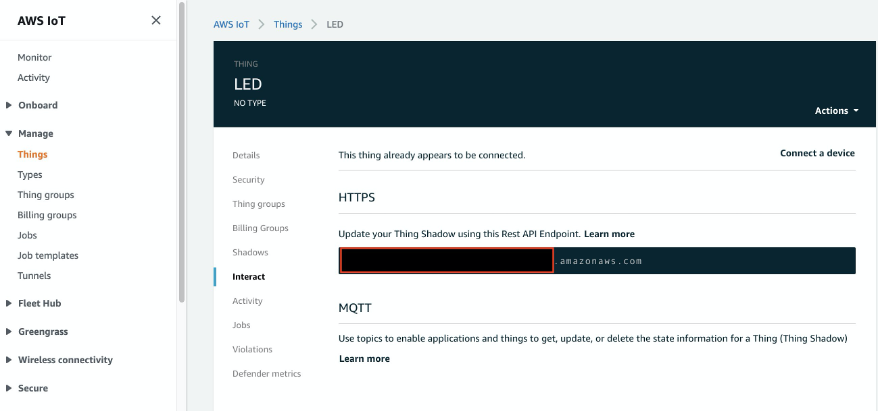
1.5 Copy your endpoint name from the AWS IoT Core console.
We need the endpoint to configure our Raspberry Pi for MQTTClient.
1. In the AWS IoT console, navigate to IoT Core, Manage, Things, select on your created thing name, on the left side select Interact.
2. Copy HTTPS endpoint.
3. Once you copied the Rest API endpoint, you need to paste it into your motion_detected.py file to connect with AWS endpoint:
4. Now, configure your credentials (with the certificates that we downloaded earlier in the step 1.2) with the code below:
Note: I renamed the downloaded certificates for the convenience as follows: root-CA.pem – which is the ‘root-CA’ certificate that we activated, LED-private.pem.key – ‘a private key’, LED.pem.crt – ‘a certificate for this thing’. as we mentioned in 1.3.
5. Once we set the variable for our MQTTClient and set the endpoint, connect to that endpoint with:
6. Since we want our motion to be detected with date and time frame, set the date variable in the code:
8. Now, its time to create a loop based on the motion detection as following:
Once you followed the steps above in the motion_detected.py document, do not forget to save it and then run the code. If everything is set up correctly, upon the movement detection within a 1–2-meter radius from the PIR sensor, you will see a message “Motion Detected” and the red LED light in your breadboard will turn on (as seen in Figure 5). Alternatively, if there’s no motion it will show “No Motion” and the LED light will turn off.
Step 2. How to stream JSON data to Amazon Kinesis Data Firehose and save into Amazon S3
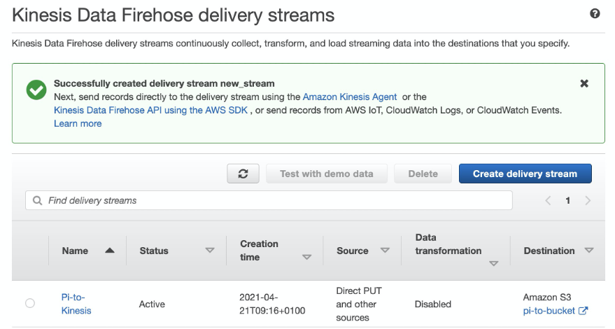
2.1. Create a delivery stream with Amazon Kinesis Data Firehose.
Once we connected our Raspberry Pi with AWS IoT Core, we need to create an Amazon Kinesis Data Firehose Delivery Stream using the following field values:
| Name | Pi-to-Kinesis |
| S3 Bucket | <Create one> |
| S3 Prefix | s3://pi-to-bucket/2021/ |
A successfully created delivery stream with the name Pi-to-Kinesis looks like this:
2.2. Configure the AWS IoT rule
After creating the Amazon Kinesis Data Firehose Stream with the defined storage location in Amazon S3, we need to set the rules for AWS IoT Core to take all the data from the topic, stream it to Amazon Kinesis Data Firehose, and save this data into the Amazon S3 bucket.
1. In the AWS IoT console, navigate to AWS IoT Core, Act, Rules, Create a rule.
Create a new AWS IoT rule with the following field values:
| Name | ‘RaspberryPiRule’ |
| Query Statement | * |
| Topic Filter | ‘topic/pi’ |
| Add Action | Send messages to Amazon Kinesis Data Firehose |
| Stream name | ‘Pi-to-Kinesis’ |
| Select Separator | ‘\n (newline)’ |
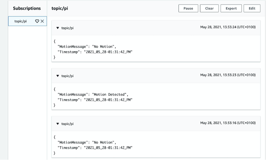
2. Let’s test if we are getting motion messages with timestamps on AWS IoT Core.
3. Navigate to AWS IoT Core, MQTT test client, subscribe to a topic, “topic/pi” (the topic name that you set in your python script), Subscribe.
4. If everything is set up correctly you will see the motion messages sent from the Pi as below:
2.3. Check the streamed data saved in Amazon S3
1. Navigate to Amazon S3 to see the bucket that you have created in step 2.1 while setting up an Amazon Kinesis stream. You will see the created S3 bucket, in my case its called ‘pi-to-bucket’.
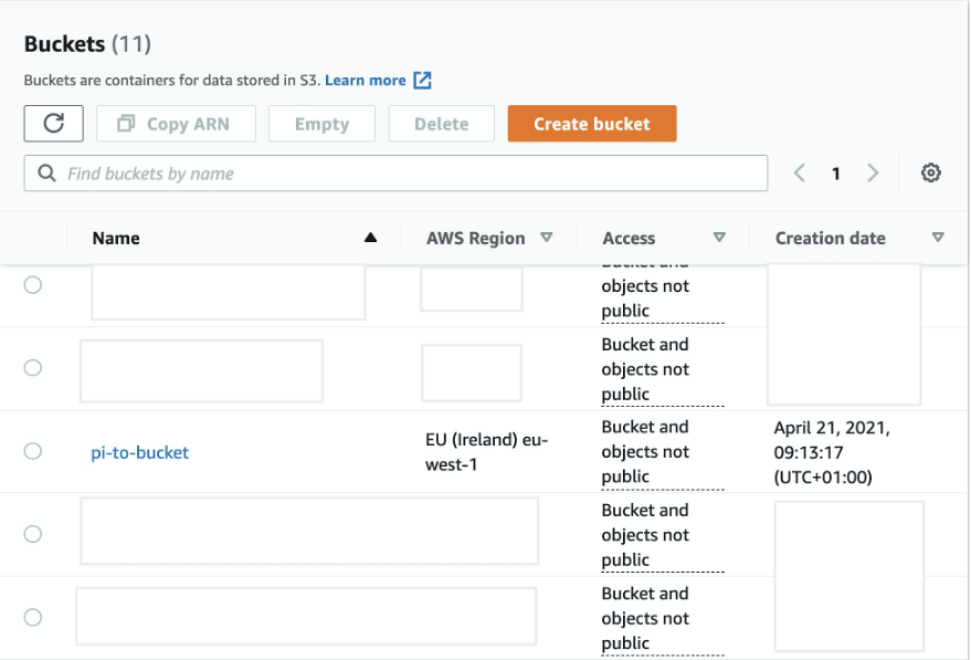
2. Select the ‘pi-to-bucket’ and check if the generated JSON data successfully saved. You will see objects in your bucket as below:
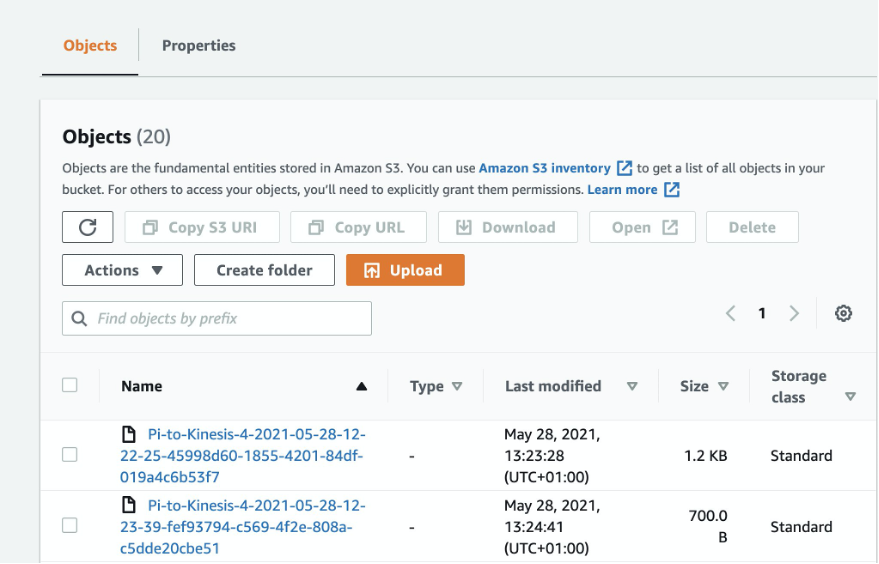
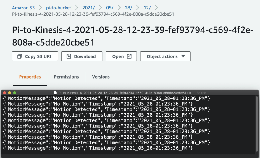
3. Select one of those objects and choose Download or Open. If everything is set correctly you will see your data as shown in the screenshot below:
Step 3. Create AWS Glue Data Catalog
Our data lake is successfully created and all the data saved securely in Amazon S3 bucket. Now, it is time to use AWS Glue to create a data catalog with a table for Amazon Athena to query this data using Simple Query Language (SQL).
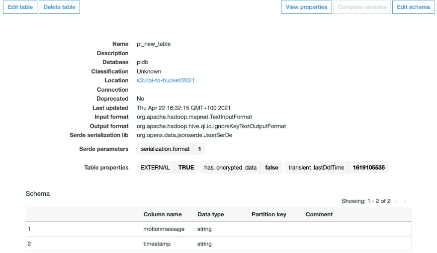
Please follow the instructions here to create a table in the AWS Glue console. You will need to create a table with column name “motionmessage” and “timestamp” with data type – string. Your table will look like this:
Step 4. Configure Amazon Athena
In the previous steps, we saw that our Raspberry Pi is successfully connected with AWS IoT Core and displays the motion messages live. We also confirmed that the stored JSON data is saved in our created Amazon S3 bucket – ‘pi-to-bucket’. Now, we want to easily analyse the stored data with an interactive query service called Amazon Athena.
Amazon Athena will play an instrumental role for the connection with the data visualisation tool Amazon QuickSight which we discuss in later steps.
* Note: for more detailed information on how to create the table please follow this instruction.
4.1. Create a simple table in Amazon Athena that will query our Amazon S3 bucket that we created earlier.
1. Log in to the Athena Console. In the Query Editor, create a table using the following query:
2. Once the table is created you can run the query below to see your data:
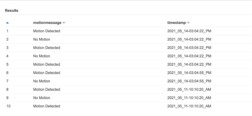
To sum up the above steps, we created a simple table with two columns: the motion message and the timestamp, then we queried the data from the Amazon S3 bucket where our PIR sensor-generated JSON data is stored.
Step 5. Visualise object movement with the Amazon QuickSight dashboard in near real-time
Now, we are ready to analyse the data in the cloud-native and fully managed business intelligence tool Amazon QuickSight.
Note: You may have to give Amazon QuickSight explicit permissions to view your Amazon Athena table.
To visualise data with Amazon QuickSight, follow these steps:
1. Open the Amazon QuickSight console.
2. Select New analysis, New dataset.
3. Choose Athena as a new data source.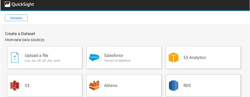
4. Set the data source name (it is a catalog name in Amazon Athena).
5. Select Create data source.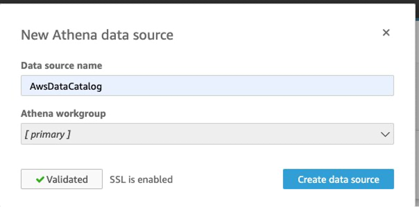
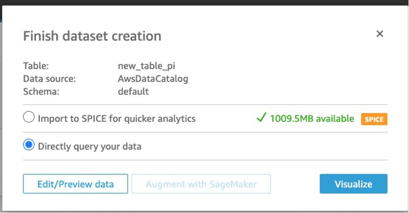
6. Once the data source is created, you need to choose a database that contains a set of tables and select the specific table which you want to visualise. Choose Select:

7. In the screenshot below you see a defined table, data source and an option to choose how you want to query your data. Select ‘Directly query your data’ and select Visualise.
8. Design the Amazon QuickSight visualisations in the drag and drop editor. You can choose any option from visual types that are listed on the left side. I selected a vertical bar chart and a donut chart which you see in the two screenshots below.
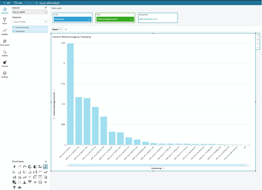
9. From the Fields list on the left pane you will see column names that we created earlier in Amazon Athena. Drag a ‘timestamp’ field to the X-axis and ‘motionmessage’ to the Value field wells.
The bar chart below shows the number of motions detected for hourly intervals over a specific period of time. For example, the highest number of motions (1.25K) in the venue was detected at 10:49 AM on April 27,2021.
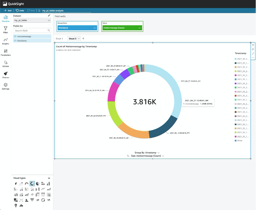
You may want to analyse the occupancy data through a different visual format. Simply choose a ‘donut chart’ in visual types and you will see the total number of motions divided across different periods. As seen on the screenshot below, 3.816K motions in total has been detected in the building across different dates and time. In particular, 33% of total movement has been noted at 10:49 AM on April 27,2021.
Conclusion
In this blog post I showed how to track, monitor, and visualise the occupancy of a building using Raspberry Pi and AWS serverless and managed services architecture. This is a scalable solution which uses cloud native services with motion sensors to get occupancy data into the cloud. You can manage and analyse the data to start building a space planning application. For example, insurance companies can assess the fire risk by knowing the capacity of the building and how often the building gets busy during different times, then build an agile application without managing any servers or provisioning the capacity.
This blog post demonstrated how to visualise data from a securely connected remote IoT device. The solution is achieved by first connecting the Raspberry Pi to AWS IoT Core using MQTT followed by forwarding messages from the topic stream using AWS IoT Rules and putting records on an Amazon Kinesis Data Firehose delivery stream. The latter, in turn, stores the data in an Amazon S3 bucket to create a data lake. AWS Glue created a data catalog with a table which is queried using Amazon Athena, and then the data is visualised using Amazon QuickSight to derive the insights on a weekly, daily or hourly basis.
To learn more, check out this blogpost on how to use Amazon QuickSight and AWS IoT Core for different use cases.
About the author

Jamila Jamilova is a Solutions Architect in the UK Public Sector. She enjoys helping customers to solve complex technical problems. Her area of interest includes Internet of Things (IoT) and Machine Learning (ML). In her spare time, she is running, playing piano and learning how to play chess.