Networking & Content Delivery
Segmenting hybrid networks with AWS Transit Gateway connect
Virtual Routing and Forwarding (VRF) is a traditional network feature which uses isolated logical routing domains (route tables/VRFs) to keep network traffic separated within the same physical infrastructure. Customers ask us how to combine the segmentation provided by AWS Cloud WAN and AWS Transit Gateway with VRF isolation when connecting their on-premises networks to AWS. In this post, we show how to use Transit Gateway connect attachments and AWS Direct Connect to connect on-premises VRFs to different Cloud WAN segments.
With Transit Gateway connect, you can build Generic Routing Encapsulation (GRE) tunnels between a transit gateway and a network appliance or router. A Transit Gateway connect attachment can use a Transit Gateway Direct Connect attachment as an underlying transport. You can create multiple Transit Gateway connect attachments to a transit gateway, terminating the GRE tunnels for each attachment in a different VRF in your on-premises network.
Architecture
In a previous post, Achieving traffic segmentation in multi-AWS Region environments using AWS Transit Gateway and AWS Cloud WAN, our colleagues introduced the use of Cloud WAN and Transit Gateway to segment traffic within a multi-Region AWS environment. We expand on their architecture to extend this segmentation to on-premises networks in multiple geographic locations.
The previous post described building traffic segmentation in the North Virginia (us-east-1) and Ireland (eu-west-1) Regions. That architecture has two different routing domains (Prod and NonProd) implemented as transit gateway route tables in each AWS Region attached to different segments in a Cloud WAN core network. This achieves cross-Region traffic segmentation between the two routing domains.
Building from the existing architecture, we add an on-premises location near each AWS Region, and extend the AWS routing domains to the on-premises network. We have simplified the topology from the previous post to a single Prod and NonProd VPC in each AWS Region as shown in in Figure 1.

Figure 1: Initial state network topology
At the conclusion of this post, the completed network with Direct Connect and Transit gateway connect attachments is as shown in Figure 2.

Figure 2: Final state network topology
Prerequisites
The following are necessary to follow the walkthrough in this post:
- Traffic segmentation within AWS using Cloud WAN and Transit Gateway is already completed by following the steps in the previous post, Achieving traffic segmentation in multi-AWS Region environments using AWS Transit Gateway and AWS Cloud WAN
- Your on-premises network devices support BGP, GRE, and VRF
Walkthrough
We walk through extending the AWS routing domains to a single on-premises location in North Virginia near the us-east-1 Region. You must repeat the walkthrough for the Ireland on-premises location near the eu-west-1 Region.
Create an AWS Direct Connect gateway
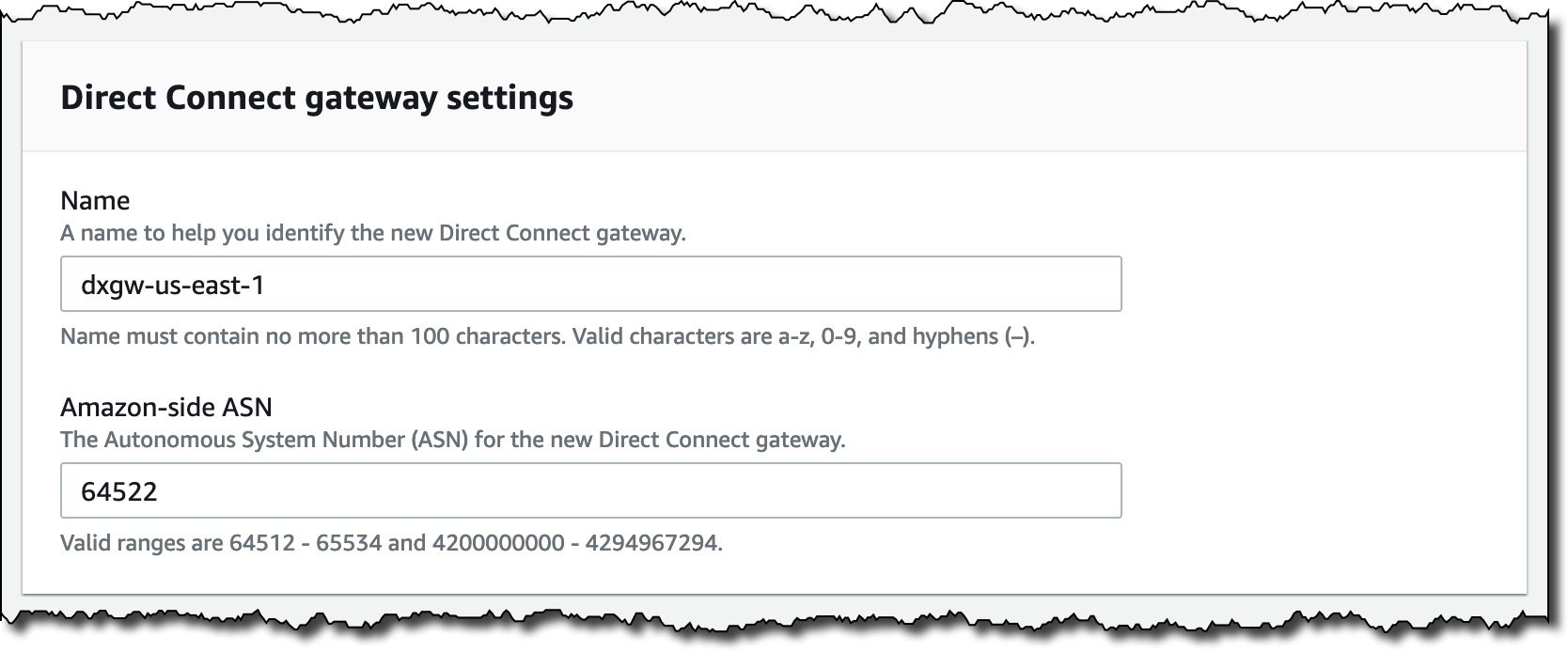
- From the Direct Connect console, select Direct Connect gateways on the left-hand side, then select the Create Direct Connect gateway button in the upper right.
- Provide a name and unique ASN as shown in the following screenshot. The Amazon-side ASN must differ from your Cloud WAN core network ASN range, your transit gateway ASN, and the ASN used in your on-premises network. Select the Create Direct Connect gateway button in the lower right.
Step 2: Configure the Direct Connect gateway
Connect the on-premises location to AWS using Direct Connect
There are different options for connecting to AWS using Direct Connect. Covering the full range of options and ordering processes is beyond the scope of this post. Whether using a dedicated connection or hosted connection from a Direct Connect Partner, make sure the connection supports a transit virtual interface (VIF).
When creating the transit virtual interface, attach it to the Direct Connect gateway you have just created as shown in Figure 3.
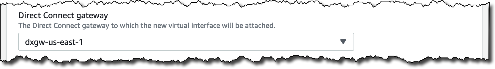
Figure 3: Attach the transit VIF to your new Direct Connect gateway
Prepare transit gateway
- From the VPC console, select Transit gateways on the left-hand side. Select your transit gateway, then from the Actions menu in the upper right, choose Modify transit gateway.
- Scroll to the bottom of the transit gateway settings, and add a transit gateway CIDR block as shown in the following screenshot. Transit Gateway selects IP addresses from this block to use as the outside addresses of the Transit Gateway connect GRE tunnels. Select the Modify transit gateway button in the lower right.
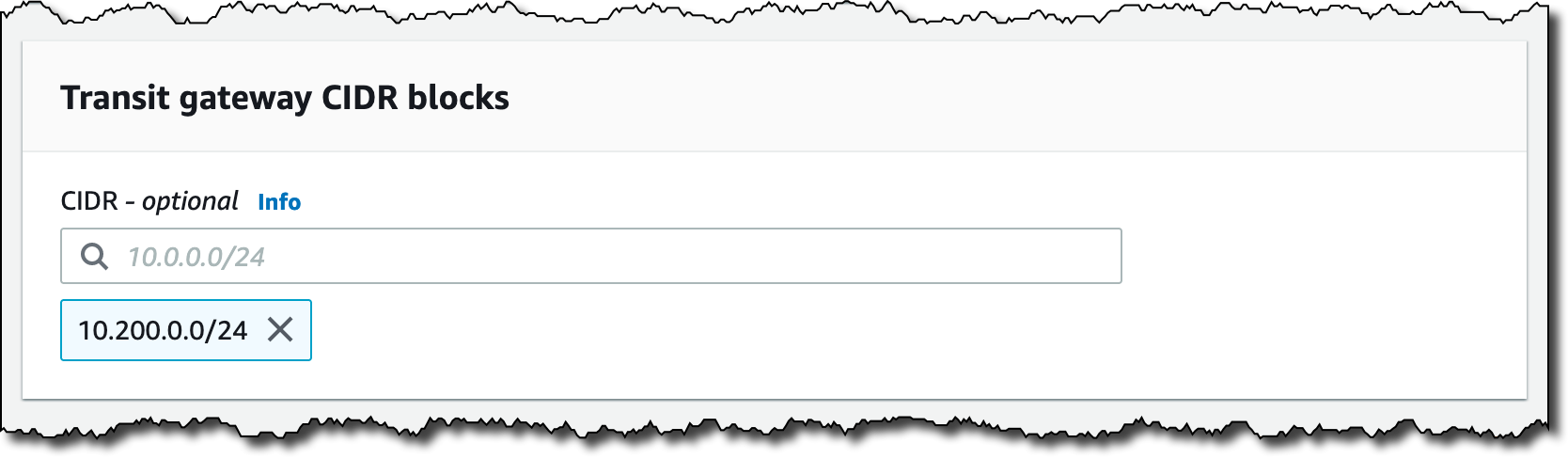
Step 2: Add a CIDR block to your transit gateway
Associate transit gateway with Direct Connect gateway
- From the Direct Connect console, select Direct Connect gateways on the left-hand side.
- From the list of Direct Connect gateways, select the gateway you just created. Select the Gateway associations tab toward the middle, then select the Associate gateway button on the right as shown in the following screenshot.
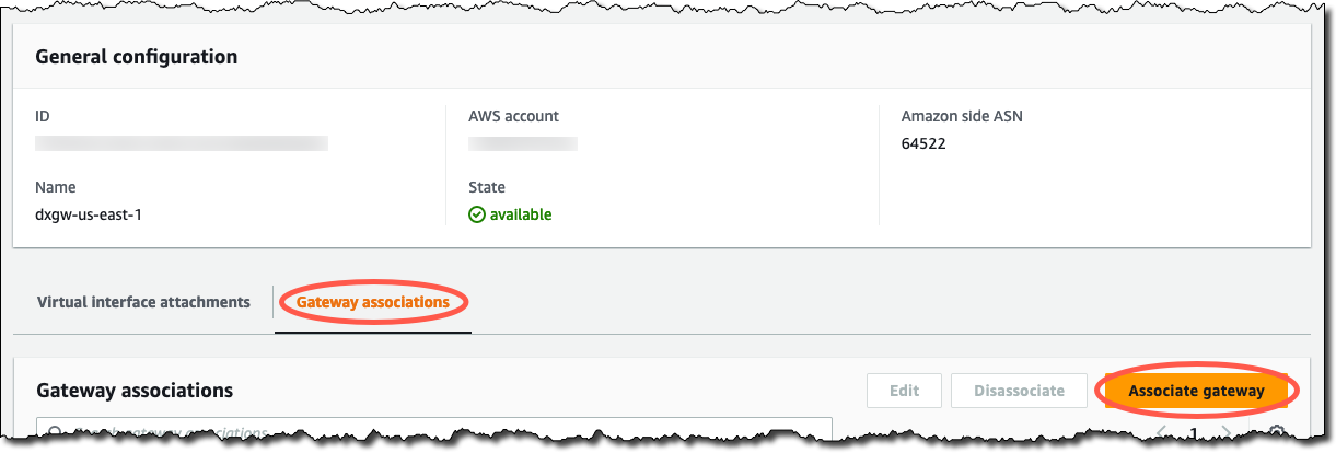
Step 2: Select the Associate gateway button under the Gateway associations tab
- Select your transit gateway and add the transit gateway CIDR block configured in the previous section as shown in the following screenshot. Adding the CIDR block here means the Direct Connect gateway advertises it to your on-premises network. Don’t add any prefixes representing the VPC CIDR blocks, as they are advertised inside the Transit Gateway connect GRE tunnels. Select the Associate gateway button in the lower right.
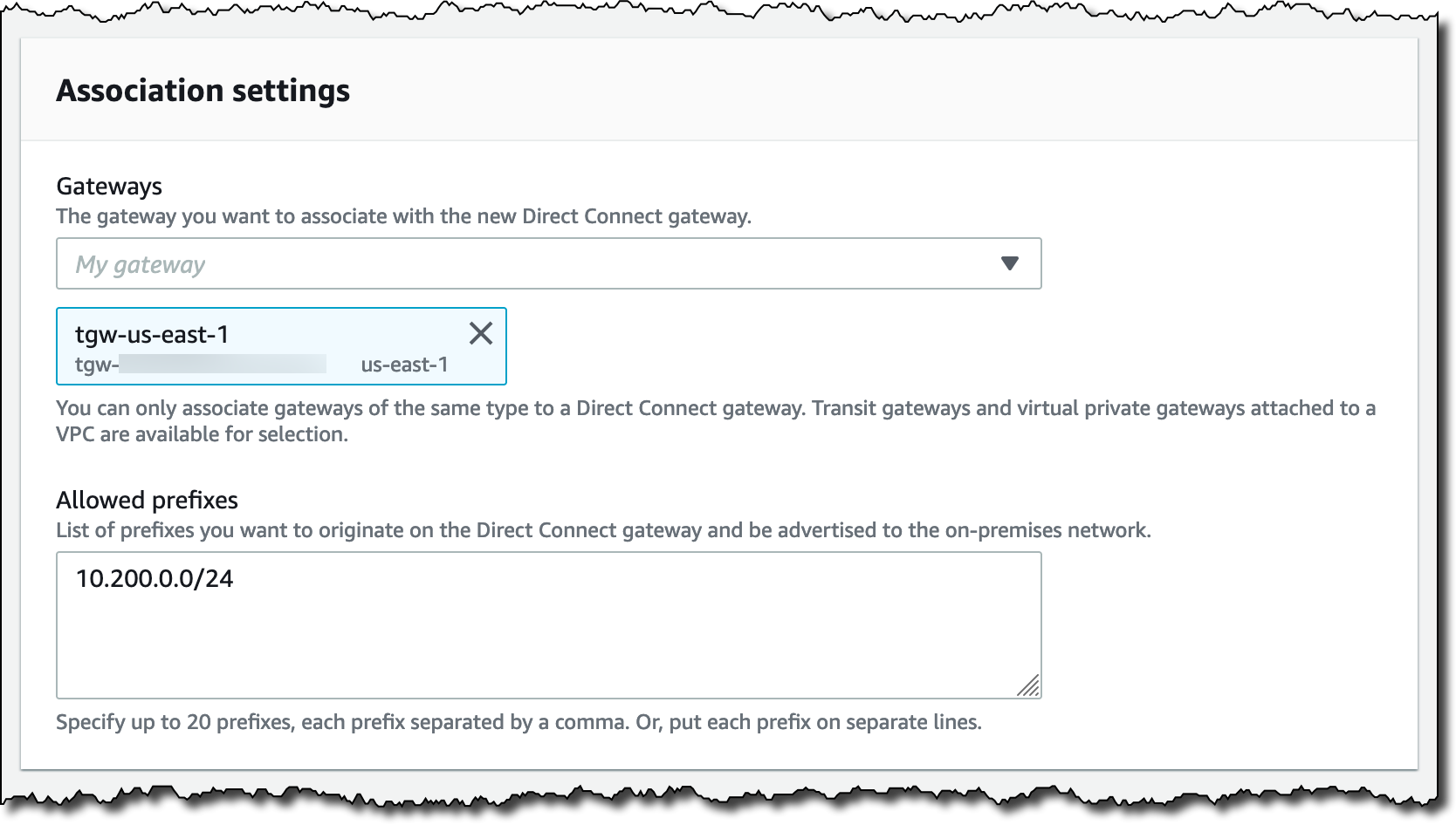
Step 3: Configure the transit gateway association
- From the VPC console, select Transit gateway attachments on the left-hand side.
- From the list of transit gateway attachments, select the Direct Connect gateway attachment. In the following Details tab, check the Association route table ID is not set. If it contains a
tgw-rtbID, then select the ID to load the relevant route table. Select the Direct Connect gateway attachment and select Delete association.
Create Transit Gateway connect attachments
Start by creating an attachment for the Prod VRF.
- From the VPC console, select Transit gateway attachments on the left-hand side, then select the Create transit gateway attachment button in the upper right.
- Provide a name for the attachment, select your transit gateway, and choose the Connect VPC attachment type. Select the transport attachment representing your Direct Connect gateway as shown in the following screenshot and select the Create transit gateway attachment button in the lower right.
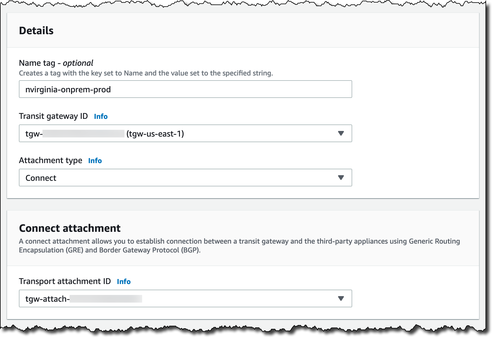
Step 2: Configure the Transit Gateway connect attachment
- From the list of transit gateway attachments, select the Transit Gateway connect attachment you just created. Select the Connect Peers tab toward the middle, then select the Create connect peer button on the right as shown in the following screenshot.
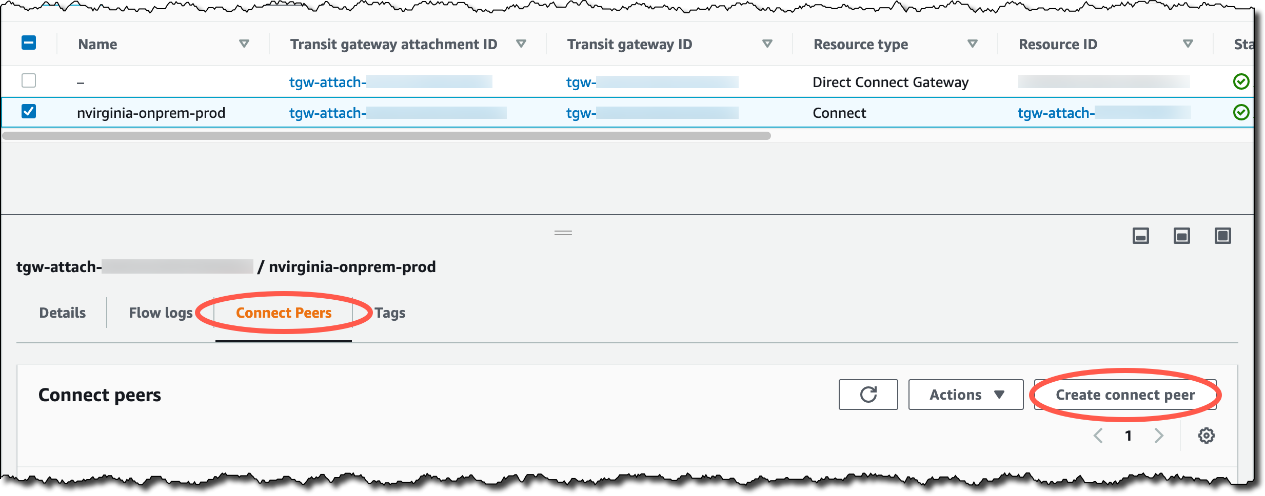
Step 3: Select the Create connect peer button under the Connect peers tab
- Provide a name for your connect peer. Leave the transit gateway GRE address blank so Transit Gateway will automatically select one from the transit gateway CIDR block. Enter a suitable address from your on-premises network as the peer GRE address. In our case, this is an address from the
10.210.0.0/24prefix advertised from the global route table of our on-premises router. Provide CIDR blocks from the permitted ranges for the inside of the GRE tunnel. Finally, enter the ASN for your on-premises network as shown in the following screenshot. Select Create connect peer in the lower right.
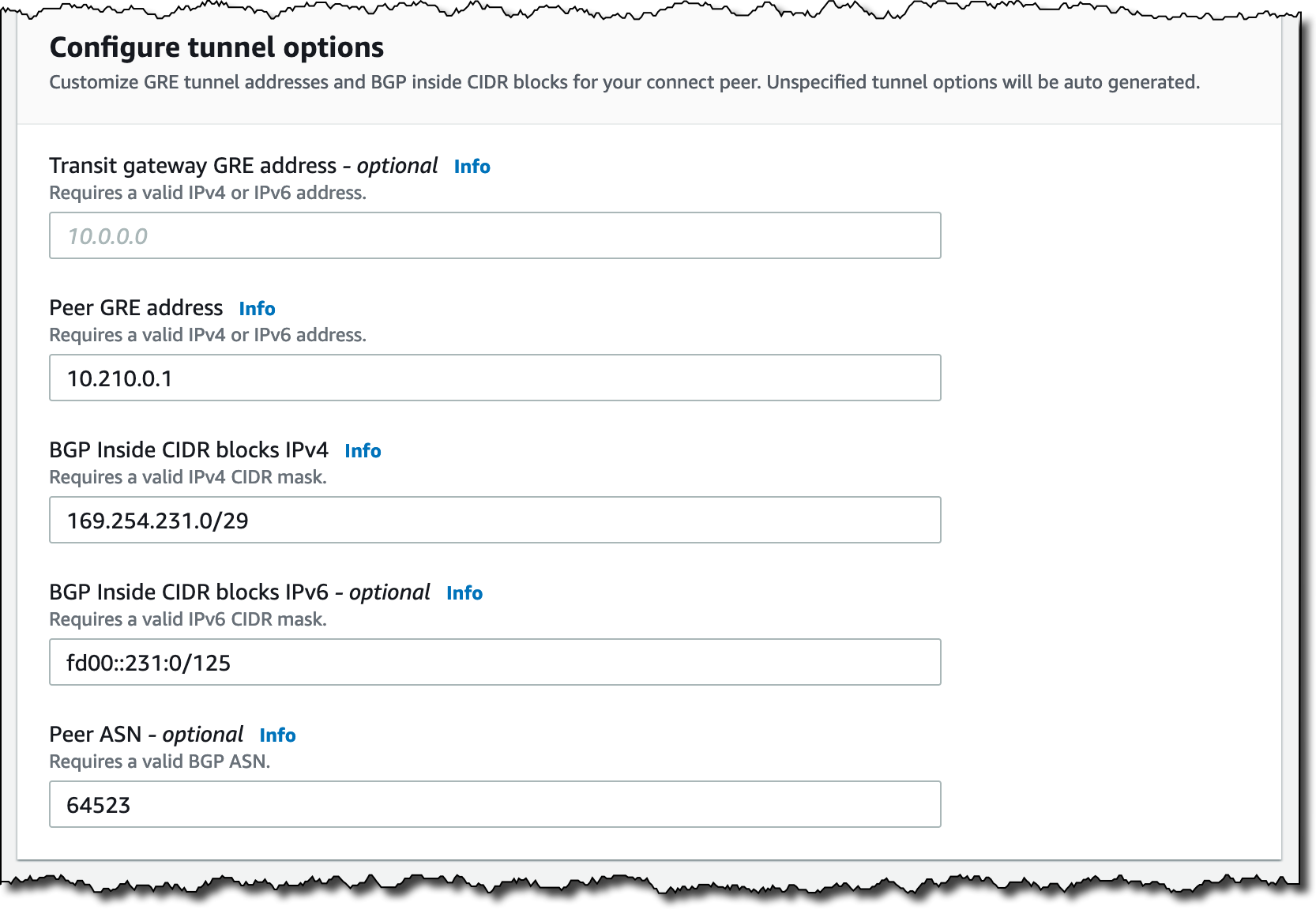
Step 4: Configure the GRE tunnel
- Make note of the Transit gateway GRE address selected by Transit Gateway. You need this address when configuring the GRE tunnel on your on-premises equipment later in the walkthrough.
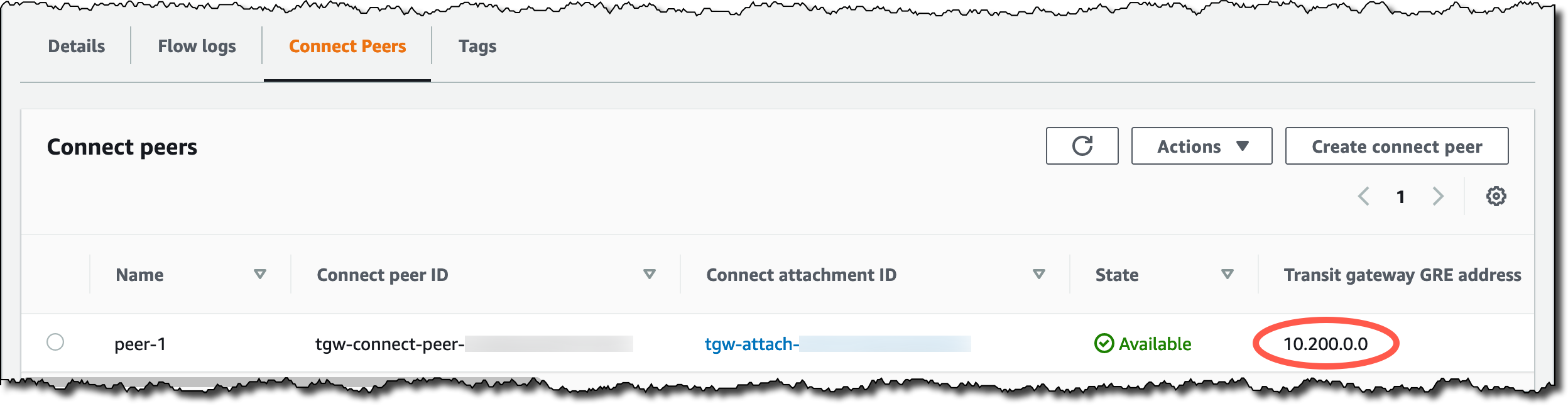
Step 5: Record the Transit gateway GRE address
- From the VPC console, select Transit gateway route tables on the left-hand side. In the list of transit gateway route tables, select the prod-rt-us-east-1 route table. Select the Associations tab toward the middle, then select the Create association button on the right.
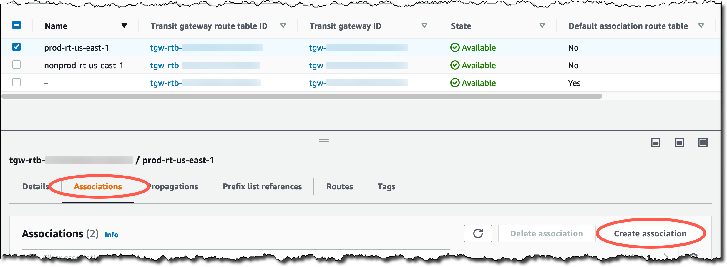
Step 6: Select the Create association button under the Associations tab
- Select the attachment representing your Prod Transit Gateway connect attachment and select the Create association button in the lower right. If you receive an error stating the attachment is already associated to a route table, delete the existing association for the attachment, and try this step again.
- Back at the transit gateway route tables list, make sure the prod-rt-us-east-1 route table is still selected. Select the Propagations tab toward the middle, then select the Create propagation button on the right.
- Select the attachment representing your Prod Transit Gateway connect attachment and select the Create propagation button in the lower right. If your transit gateway has default route table propagation configured, disable propagation of the Transit Gateway connect attachment to that route table.
Repeat the Transit Gateway connect steps for the NonProd VRF, selecting unique inside CIDR blocks for the Transit Gateway connect peer. Associate the NonProd Transit Gateway connect attachment to the nonprod-rt-us-east-1 transit gateway route table and create a propagation for the attachment.
Finally, repeat the entire walkthrough above for the on-premises location near the eu-west-1 Region.
Configure on-premises network
We have used a Cisco configuration in our example, and the exact commands used will vary based on your specific on-premises equipment and network configuration. For simplicity, we are using a single Direct Connect connection at each on-premises location. We recommend following the AWS Direct Connect resiliency recommendations to match the availability requirements for your network.
- Configure your router’s network interface and transit VIF BGP session. In our example, we are advertising
10.210.0.0/24from the router’s global route table, and using an IP address from this /24 as the GRE outside address.
interface GigabitEthernet0/0/1.101
 description Direct Connect to AWS
 encapsulation dot1Q 101
 ip address 169.254.96.14 255.255.255.248
!
router bgp 64523
 network 10.210.0.0 mask 255.255.255.0
 neighbor 169.254.96.9 remote-as 64522
 neighbor 169.254.96.9 password **********
- Bind the GRE outside address to a loopback interface so it is always available. Create the GRE tunnel interfaces to terminate the on-premises end of the Transit Gateway connect peers into their respective VRFs. Use the transit gateway GRE address you recorded earlier as the tunnel destination address.
interface Loopback0
 ip address 10.210.0.1 255.255.255.255
!
interface Tunnel0
 ip vrf forwarding Prod
 ip address 169.254.231.1 255.255.255.248
 tunnel source 10.210.0.1
 tunnel destination 10.200.0.0
!
interface Tunnel1
 ip vrf forwarding NonProd
 ip address 169.254.232.1 255.255.255.248
 tunnel source 10.210.0.1
 tunnel destination 10.200.0.1
- Establish the Transit Gateway connect BGP sessions from inside each VRF. Advertise the Prod and NonProd IP prefixes to the transit gateway. Transit Gateway connect eBGP sessions must be configured using BGP multihop. The remote ASN for the Transit Gateway connect sessions is that of the transit gateway, while the ASN for the transit VIF session is that of the Direct Connect gateway.
router bgp 64523
 !
 address-family ipv4 vrf NonProd
  network 10.100.3.0 mask 255.255.255.0
  neighbor 169.254.232.2 remote-as 64521
  neighbor 169.254.232.2 ebgp-multihop 2
  neighbor 169.254.232.2 activate
  neighbor 169.254.232.3 remote-as 64521
  neighbor 169.254.232.3 ebgp-multihop 2
  neighbor 169.254.232.3 activate
 exit-address-family
 !
 address-family ipv4 vrf Prod
  network 10.100.0.0 mask 255.255.255.0
  neighbor 169.254.231.2 remote-as 64521
  neighbor 169.254.231.2 ebgp-multihop 2
  neighbor 169.254.231.2 activate
  neighbor 169.254.231.3 remote-as 64521
  neighbor 169.254.231.3 ebgp-multihop 2
  neighbor 169.254.231.3 activate
 exit-address-family
After you configure the on-premises equipment at the North Virginia on-premises location, you must repeat the process for the Ireland on-premises location.
Verify route exchange – on-premises
From the North Virginia on-premises router, confirm that you have:
- received the transit gateway CIDR block
10.200.0.0/24by using BGP to the Direct Connect gateway in the global table - originated the GRE outside prefix
10.210.0.0/24:
nvirginia-onprem#sh ip bgp
...
     Network          Next Hop            Metric LocPrf Weight Path
 *>   10.200.0.0/24    169.254.96.9                           0 64522 i
 *>   10.210.0.0/24    0.0.0.0                  0         32768 i
Moving now to the Prod VRF, confirm you have:
- received us-east-1 Prod VPC CIDR block
10.0.0.0/24 - received eu-west-1 Prod VPC CIDR block
10.1.0.0/24 - received Ireland on-premises Prod VRF prefix
10.101.0.0/24 - originated the North Virginia on-premises Prod VRF prefix
10.100.0.0/24:
nvirginia-onprem#sh ip bgp vpnv4 vrf Prod
...
     Network          Next Hop            Metric LocPrf Weight Path
Route Distinguisher: 64523:1 (default for vrf Prod)
 *    10.0.0.0/24      169.254.231.2          100             0 64521 i
 *>                    169.254.231.3          100             0 64521 i
 *    10.1.0.0/24      169.254.231.2          100             0 64521 64512 64513 64531 i
 *>                    169.254.231.3          100             0 64521 64512 64513 64531 i
 *>   10.100.0.0/24    0.0.0.0                  0         32768 i
 *    10.101.0.0/24    169.254.231.3          100             0 64521 64512 64513 64531 64533 i
 *>                    169.254.231.2          100             0 64521 64512 64513 64531 64533 i
For the NonProd VRF, confirm you have received and originated the equivalent NonProd prefixes:
nvirginia-onprem#sh ip bgp vpnv4 vrf NonProd
...
     Network          Next Hop            Metric LocPrf Weight Path
Route Distinguisher: 64523:2 (default for vrf NonProd)
 *    10.0.3.0/24      169.254.232.2          100             0 64521 i
 *>                    169.254.232.3          100             0 64521 i
 *    10.1.3.0/24      169.254.232.2          100             0 64521 64512 64513 64531 i
 *>                    169.254.232.3          100             0 64521 64512 64513 64531 i
 *>   10.100.3.0/24    0.0.0.0                  0         32768 i
 *    10.101.3.0/24    169.254.232.2          100             0 64521 64512 64513 64531 64533 i
 *>                    169.254.232.3          100             0 64521 64512 64513 64531 64533 i
Heading east to the Ireland on-premises router, you can see the eu-west-1 transit gateway CIDR block and on-premises GRE outside prefix in the global table:
ireland-onprem#sh ip bgp
...
     Network          Next Hop            Metric LocPrf Weight Path
 *>   10.201.0.0/24    169.254.96.17                          0 64532 i
 *>   10.211.0.0/24    0.0.0.0                  0         32768 i
And the correct prefixes in each VRF:
ireland-onprem#sh ip bgp vpnv4 vrf Prod
...
     Network          Next Hop            Metric LocPrf Weight Path
Route Distinguisher: 64533:1 (default for vrf Prod)
 *    10.0.0.0/24      169.254.131.3          100             0 64531 64513 64512 64521 i
 *>                    169.254.131.2          100             0 64531 64513 64512 64521 i
 *    10.1.0.0/24      169.254.131.3          100             0 64531 i
 *>                    169.254.131.2          100             0 64531 i
 *    10.100.0.0/24    169.254.131.2          100             0 64531 64513 64512 64521 64523 i
 *>                    169.254.131.3          100             0 64531 64513 64512 64521 64523 i
 *>   10.101.0.0/24    0.0.0.0                  0         32768 i
ireland-onprem#sh ip bgp vpnv4 vrf NonProd
...
     Network          Next Hop            Metric LocPrf Weight Path
Route Distinguisher: 64533:2 (default for vrf NonProd)
 *    10.0.3.0/24      169.254.132.2          100             0 64531 64513 64512 64521 i
 *>                    169.254.132.3          100             0 64531 64513 64512 64521 i
 *    10.1.3.0/24      169.254.132.2          100             0 64531 i
 *>                    169.254.132.3          100             0 64531 i
 *    10.100.3.0/24    169.254.132.2          100             0 64531 64513 64512 64521 64523 i
 *>                    169.254.132.3          100             0 64531 64513 64512 64521 64523 i
 *>   10.101.3.0/24    0.0.0.0                  0         32768 i
Verify route exchange – Transit Gateway
Moving into the AWS network, observe the Prod and NonProd transit gateway route tables in us-east-1 as shown in Figure 4 and 5 respectively. For each route table, you must verify the following:
- the on-premises prefix has been learned using the Transit Gateway connect attachment
- the local VPC CIDR block has been learned using the VPC attachment
- the two prefixes from eu-west-1 (the Ireland on-premises prefix and eu-west-1 VPC CIDR block) have been learned using the peering attachment to Cloud WAN
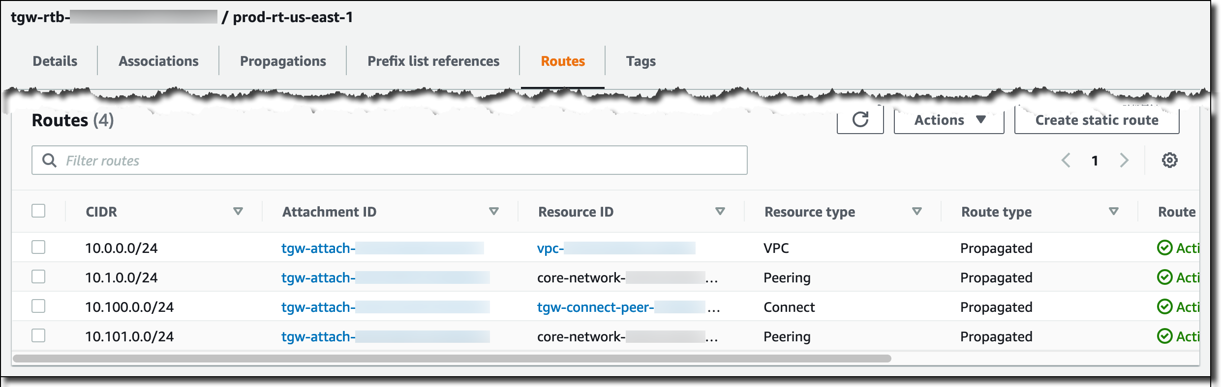
Figure 4: us-east-1 transit gateway Prod route table
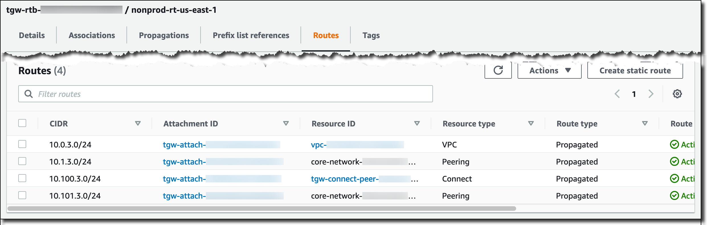
Figure 5: us-east-1 transit gateway NonProd route table
Verify route exchange – AWS Cloud WAN
Finally, check the view of the global network from the us-east-1 perspective of Cloud WAN as shown in Figure 6 (Prod) and Figure 7 (NonProd). In each segment, the us-east-1 prefixes (VPC and on-premises) are learned using the transit gateway, while the two eu-west-1 prefixes are propagated from the core network edge in that AWS Region.
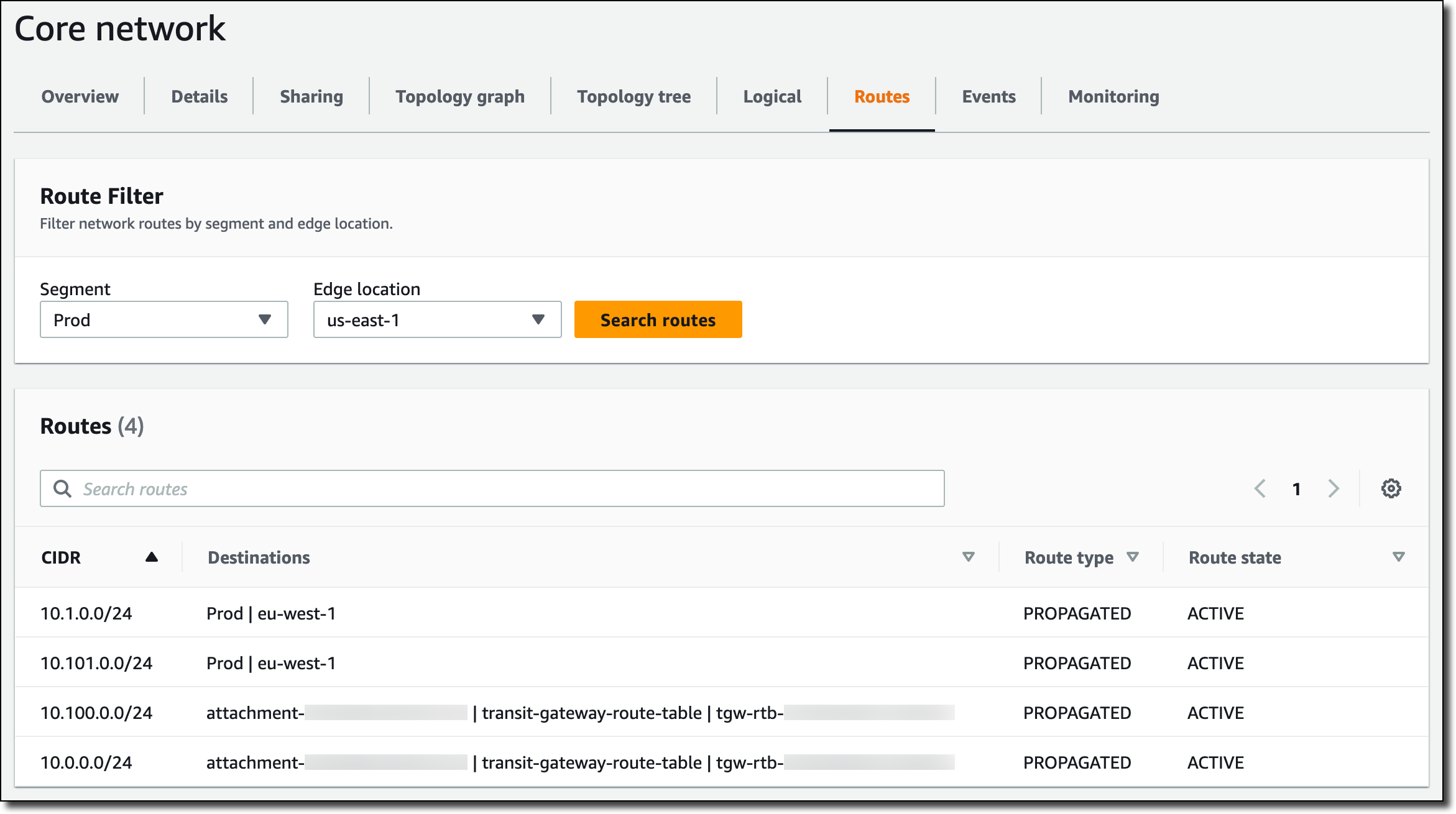
Figure 6: us-east-1 Cloud WAN Prod segment routes
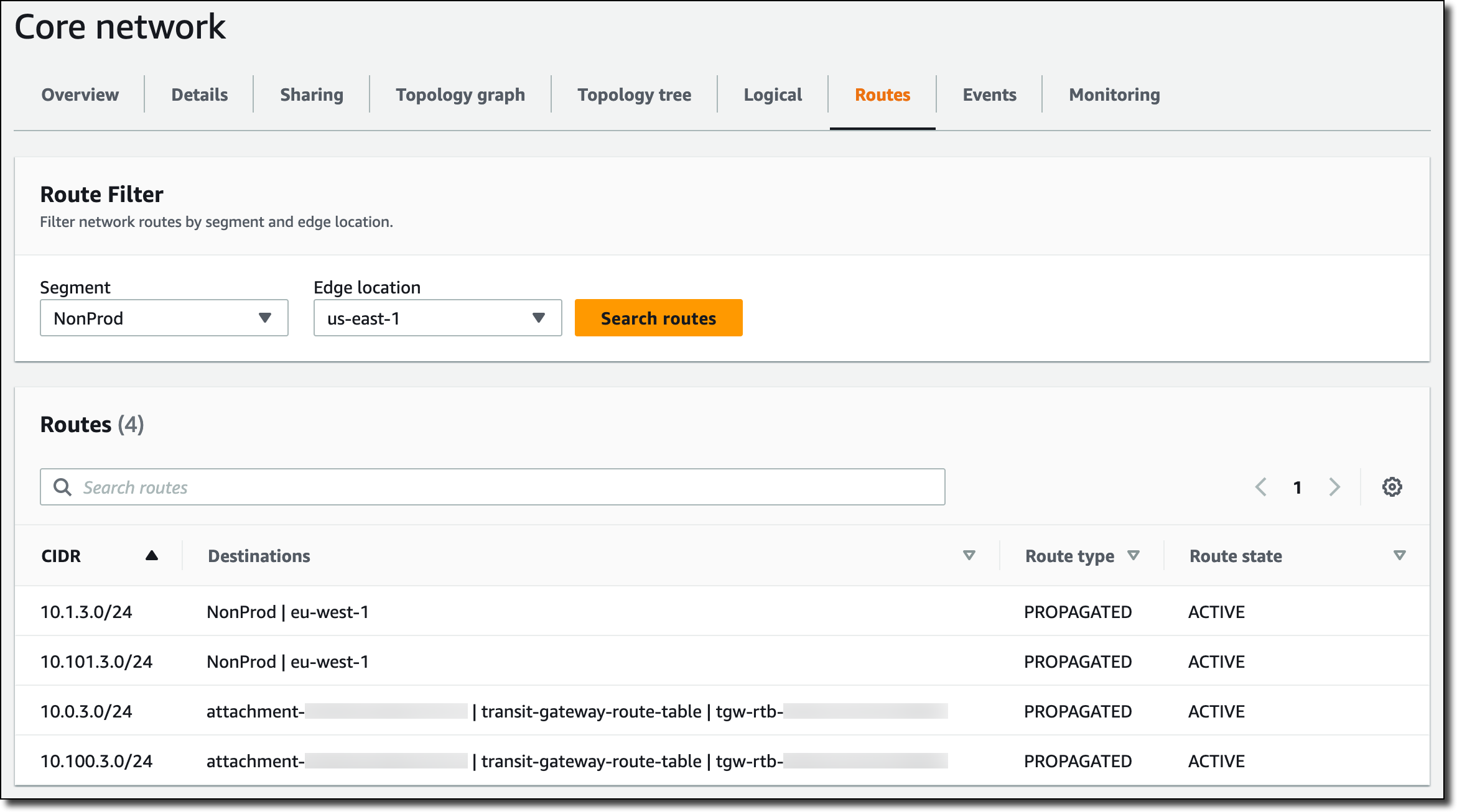
Figure 7: us-east-1 Cloud WAN NonProd segment routes
Considerations
Consider the following points when designing your solution:
- Transit Gateway connect attachments support a maximum of 5 Gbps through each peer (a single GRE tunnel). You can create up to four peers per attachment, supporting up to 20 Gbps per attachment with equal-cost multi-path (ECMP). The underlying Direct Connect transport connectivity must be large enough to support the aggregate bandwidth of the GRE tunnels
- Each Transit Gateway connect attachment incurs an hourly charge
- Although the VPCs were attached to an existing transit gateway in this architecture, they could also be attached natively to Cloud WAN. However, Cloud WAN does not natively support Direct Connect gateway attachments, so you must use transit gateway to connect Cloud WAN to Direct Connect
Cleanup
To clean up the infrastructure created, delete the Transit Gateway connect attachments, transit gateway association to the Direct Connect gateway, and Direct Connect gateway that you created during the walkthrough.
Conclusion
In this post, we walked through using Transit Gateway connect with Direct Connect to extend Cloud WAN segmentation to on-premises networks in multiple geographic locations, achieving hybrid network segmentation. To learn more about the services in this post, visit the documentation for Transit Gateway connect, Transit Gateway, Direct Connect, and Cloud WAN.

Mike Jager
Mike is a Senior Cloud Architect based in Auckland, New Zealand. As an infrastructure specialist with a strong bias towards networking, he has spent his career working to architect, design, build, and operate networks and systems across Asia-Pacific.

Dennis Lin
Dennis is a Cloud Architect based in Sydney, Australia, specializing in Cloud Infrastructure. He is a passionate builder and helps customers across APJ to build on AWS. In his spare time, he enjoys building LEGO sets and travel.
This post was updated on March 22, 2024 to replace sensitive terms with more descriptive alternatives.