Microsoft Workloads on AWS
Deploying Microsoft Always On VPN on AWS
In this blog post, I will detail how to create a cost-effective, secure, and resilient VPN remote access architecture on AWS. With the increasing number of full-time remote employees and a mobile workforce, the requirement for remote access has moved from a nice-to-have feature to one that can have a significant financial impact in the event of outages. Traditionally, equipment running in data centers provided remote access, which made increasing the resiliency of the remote access service expensive or, sometimes, technically unfeasible. With other mission-critical workloads already deployed in AWS, enterprises are now looking to migrate their remote access workload into the AWS Cloud to take advantage of the resiliency AWS provides.
The basic components of a remote access service include a VPN server and a VPN client application installed on the end-user’s device. The need to remember when and how to start a VPN connection can have a negative impact on end user productivity. Prior to establishing a VPN connection, the device is in a disconnected state, which affects the ability of enterprise IT to monitor and manage mobile end-user devices.
To address these issues, Microsoft provides a technology solution, Always On VPN. As the name implies, with this technology, the VPN connection is always on with no user interaction required. Microsoft Windows servers running on Amazon Elastic Compute Cloud (Amazon EC2) instances provide the Always On VPN server backend. Using the native Microsoft stack, enterprises can avoid additional VPN licensing costs normally associated with traditional VPN architecture. AWS services provide the resilient VPN server architecture that can withstand the failure of a single Amazon EC2 instance, an entire Availability Zone (AZ), or an entire AWS Region.
Solution overview
For ease of deployment, the goal is to provide one VPN configuration to all clients. Using a combination of AWS and Microsoft technologies, we can accomplish this. Figure 1 illustrates the resulting Always On VPN architecture running in AWS.
- An Amazon Virtual Private Cloud (VPC) with public and private subnets across two AZs deployed in two distinct regions.
- Amazon EC2 instances running Windows Server 2016 or above with Routing and Remote Access (RRAS) , Network Policy Server (NPS), Certificate, and Domain controller roles. The RRAS and NPS servers are load-balanced with AWS Network Load Balancers (NLBs).
- A client that connects to the remote access architecture is outside of the VPC and establishes the VPN connection across the public internet.
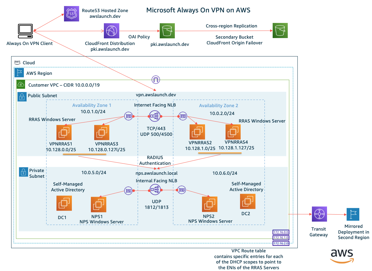
Figure 1 – Always On VPN Architecture
Implementing Always On VPN: Modern Mobility with Microsoft Windows 10 and Windows Server 2022 book by Richard Hicks completely explains Always On VPN. This book goes into the exact configuration details of the Microsoft components required for Always On VPN implementation.
Solution walkthrough
Complete the following steps to create the Always On VPN architecture on AWS:
- Configure the Microsoft Windows Server roles.
- Configure the Microsoft Windows client.
- Create the AWS configuration.
Configure the Microsoft Windows Server roles
Step 1: Prepare the Active Directory and PKI environment
Microsoft Active Directory security groups provide security controls for certificate templates and govern which users and devices can establish a VPN connection. At a minimum, security groups for VPN users, VPN devices, and NPS servers are required. There is no technical requirement to join the RRAS servers to Active Directory for this solution but it may be required per organizational policy. If so, create an additional security group for them.
This solution heavily relies on security certificates. The Microsoft guide, Always On VPN Deployment, explains how to create the required certificate templates. These templates include certificates for the VPN (RRAS) servers, NPS servers, users, and devices. Because the Secure Socket Tunneling Protocol (SSTP) uses HTTPS for transport, a public or internal certificate authority (CA) should issue a respective certificate. If internal CA issues the certificate, the certificate revocation list (CRL) must be publicly accessible. Certificates in this solution are all generated internally from a 2-tier Microsoft PKI deployment on AWS. The QuickStart Microsoft Public Key Infrastructure on AWS provides more details about running Microsoft PKI on AWS.
When looking at this solution, some common questions may be “How many RRAS (VPN) servers do I need?” and “What EC2 instance size should I choose?”. Currently, there are no published RRAS capacity planning guidelines. Some organizations may have a negligible amount of network traffic going through the VPN tunnel, and other organizations may require all remote access traffic to flow through the VPN tunnel. Understanding the expected network traffic flow will help to determine capacity requirements. The Amazon EC2 instance network bandwidth document explains the network throughput capacity across the Amazon EC2 instance families.
Another consideration is the total number of connections that need to be supported in the environment. Please note that, in total, there are 2 connections—one for the user and one for the device—for each deployed client. Once the total number of connections is determined, decide on the overall VPC client IP address range to assign. Each RRAS server must have a unique DHCP CIDR range of IP addresses to hand out to the clients connecting through the VPN, which will be entered later into the VPC route tables. Divide the overall VPC client CIDR range by the number of RRAS servers. Refer to Figure 2 for an example of the VPC client CIDR ranges assigned to each RRAS server.
Step 2: Create the VPN (RRAS) server configuration
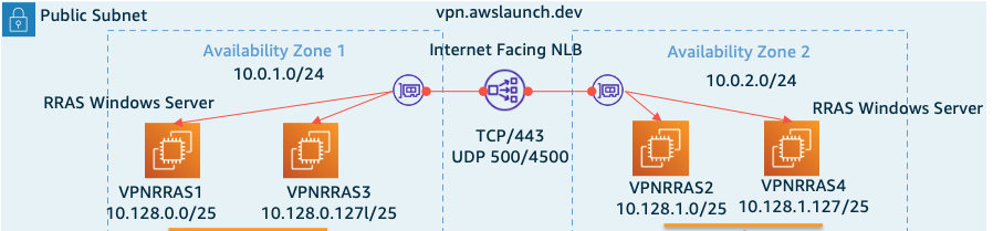
Figure 2 – VPN (RRAS) Architecture
In this example, the total number of clients to be supported is 200. Each Amazon EC2 instance hosting the RRAS can handle up to 100 connections. So why are there 4 servers instead of just 2? Because we need to consider the resiliency of the solution. If we experience a complete AZ failure, we need capacity in the secondary AZ to handle all the client traffic. This architecture is an example of static stability using AZs.
We place the Amazon EC2-based RRAS servers into the public subnets across AZs and regions using the following configuration.
- Launch an Amazon EC2 Windows Server 2022 instance and enable the RRAS Server Role (VPN Only).
- Configure the Amazon EC2 network adapter (ENI) with Source/Destination Checking Disabled.
- Create an Amazon EC2 security group that includes TCP/443 (SSTP connections) and UDP 500/4500 (IKEv2 connections) and assign it to each Amazon EC2 instance.
- Allocate server certificates that match the external DNS name (e.g., vpn.example.com) to be used for SSTP and IKEv2 connections and place them in the local machine certificate store. In this example, the RRAS servers are not joined to a domain, which requires importing the internal Root and Issuing CAs into the local machine store. Use the PowerShell command Set-VPNAuthProtocol to only accept certificates from the internal PKI.
Except for the DHCP range of addresses that are allocated to each RRAS server, their configuration is identical. Authentication is provided by the NPS server using RADIUS Authentication. The value for the RADIUS server name will be the DNS name of the internal facing AWS NLB. The only authentication methods allowed are Extensible Authentication Protocol (EAP) and allow machine certification authentication for IKEv2. The SSL certificate generated for SSTP connections is specified in the SSL Certificate Binding section. Additional VPN optimizations and PowerShell scripts can be found on Richard Hicks’ GitHub.
Step 3: Create NPS server configuration
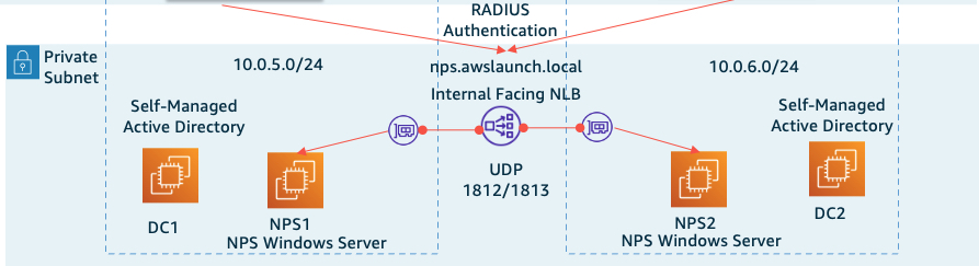
Figure 3 – NPS Architecture
The NPS servers provide authentication for VPN clients connecting through the RRAS service. Figure 3 illustrates the NPS servers placed into private subnets. These NPS servers have an identical configuration that includes the following elements:
- Launch an Amazon EC2 Windows Server 2022 instance and enable the NPS Server Role.
- Create an Amazon EC2 security group that allows UDP 1812/1813 for RADIUS traffic and assign it to each Amazon EC2 instance.
- Create a server certificate that matches the DNS name of the internal-facing AWS NLB.
- On the NPS server, register each of the RRAS servers as NPS clients. Even though the VPN EC2 instances direct their RADIUS traffic to the AWS NLB, the NPS server will see the IPv4 host address of the VPN (RRAS) server.
- Configure the NPS server to only allow the security group of the VPN users using Microsoft Protected (PEAP) only. Once the configuration is complete on one NPS server, the configuration can be exported and imported to the remaining NPS servers.
- We have an AWS NLB per region, but only a single custom DNS name. Microsoft DNS Query Policy records are used to point to the AWS NLBs in each region.
Microsoft Windows client configuration
The device tunnel is established as soon as the workstation is booted and has a network connection. The user tunnel is established after the user logs into the workstation. The profiles can be deployed using either the Microsoft Endpoint Manager or via PowerShell with a XML configuration file that is deployed by SCCM, Active Directory GPO, or other client deployment management tools. Perform the following steps on the client:
- Certificate Verification – Verify that the client workstation has both the user and device certificates installed. The device certificate will be found in the local machine store and the user certificate in the user store.
- User Tunnel – Create a VPN profile using the Windows built-in VPN client providing the public DNS name of the VPN server AWS NLB. The type is SSTP and the sign-in info is Microsoft Protected EAP (PEAP). The NPS custom DNS name and internal Root CA certificates are specified. The authentication method will be a user-based certificate instead of a username / password combination. Test the connection to make sure it is successful. The profile will later be exported for deployment to all devices.
- Device Tunnel – The setup of the Device Tunnel is similar except the VPN type will be IKEv2, and the choice will be made to use machine certificates.
The Windows client will show a status of connected if the VPN connection is successful, as shown in Figure 4.
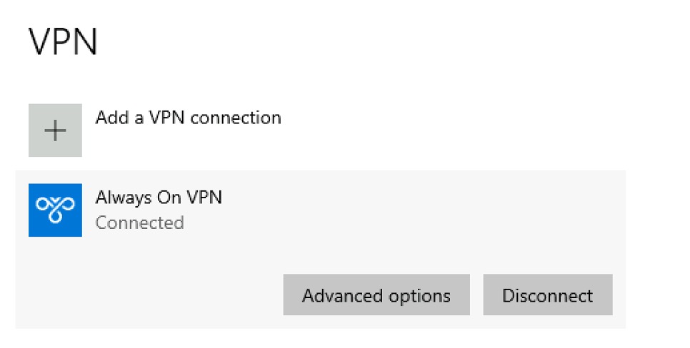
Figure 4 – Client VPN Connection Status
Create the AWS configuration
This solution uses several AWS services, including Amazon CloudFront, Amazon EC2, Network Load Balancers (NLBs), Amazon Route 53, Amazon Simple Storage Service (Amazon S3), and VPC Route Tables.
Step 1: Microsoft CRL configuration with Amazon CloudFront and Amazon S3
All elements of the solution should be resilient. The certificate revocation list (CRL) is included within the properties of issued certificates. This CRL needs to be available to the client when establishing the VPN connection over HTTP. An internal Microsoft CA is used to issue certificates in this example. Amazon CloudFront and Amazon Simple Storage Service (Amazon S3) will provide the resilient architecture for public availability of the CRL.
Whenever a new CRL is published from the CA, a new version of the CRL is copied to the primary Amazon S3 bucket. Cross-region replication copies the object to the secondary Amazon S3 bucket in another region. A CloudFront distribution front-ends the Amazon S3 buckets using Origin Access Identity policies. To ensure that only the latest CRL is returned, caching is disabled on the CloudFront distribution. The Amazon S3 origins are set up in an origin group to provide resilience at the CRL distribution layer. An Amazon Route 53 DNS alias record will then point to the CloudFront distribution. Figure 5 illustrates the design of the CloudFront architecture:
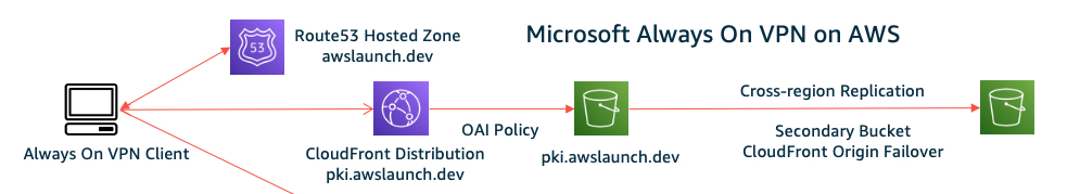
Figure 5 – CloudFront and S3 Architecture
Step 2: Network Load Balancer (NLB) configuration
This architecture uses 2 NLBs. One is external for the VPN (RRAS) servers and the other one is internal for the NPS servers. The internet-facing NLB listens on ports TCP/443 and UDP 500/4500, which directs traffic to the RRAS servers. The internal-facing NLB listens on UDP ports 1812/1813 for RADIUS traffic.
Step 3: VPC route tables
Once a client connects, the client will be given an IPv4 address from the static pool defined on the RRAS servers. For each VPN client CIDR range, the VPC route table will contain an entry to the ENI of the RRAS server that is handing out those addresses. Destination hosts will then know how to route traffic back to the VPN client.
Step 4: Amazon Route 53 DNS records
To achieve protection from regional failure, you will need to create a primary and failover set of DNS records within Amazon Route 53. Route 53 DNS alias records are created to point to the internet-facing NLBs in the primary and secondary regions. See Failover routing in the Amazon Route 53 documentation for more information.
Amazon Route 53 is a key component of the resilient architecture that will failover the client in the event of a complete regional outage. The Amazon Route 53 health checks are created using the Amazon Route 53 data plane. To learn more, refer to Creating Disaster Recovery Mechanisms Using Amazon Route 53.
Failover testing
The architecture must be resilient to the failure of a single Amazon EC2 instance, an AZ, or an entire region. By selectively shutting down individual Amazon EC2 servers across the environment, these failover scenarios can be tested. As a feature of Always On VPN, without any user interaction, the VPN client will recover and continue to stay connected to the VPN architecture during these failover scenarios.
As configured, the architecture represents an active/passive configuration. It is possible that other Amazon Route 53 routing policies like Geolocation, Latency, or Weighted could be used to create an active/active configuration while still enabling a complete regional failover. Failing over an entire region will take significantly longer than failover within a region. Amazon Route 53 alias records have a TTL of 60 seconds, along with any DNS caching at the client side.
Conclusion
While we can’t control when systems will fail, we can do our best to develop architectures that are resilient to individual component failures of the overall system. Stephen Orban makes reference in his book, “Ahead in the Cloud”, of architectures that are “disaster indifferent.”. That is a great way to think about cloud architecture with the goal of moving beyond disaster recovery to disaster indifference.
As the number of remote workers has increased, providing remote access is a core business requirement. For organizations that have a large installed base of Microsoft Windows 10+ clients, the ability for the Windows 10+ client to use Always On VPN is a huge productivity booster. With Always On VPN, whenever the device is off the corporate network, the client will automatically tunnel a VPN connection without the need for user interaction or additional client-side VPN software.
Combined with AWS services, it is possible to create a robust and resilient remote access Always On VPN architecture for Windows 10+ clients on AWS. In this blog post, we explored the configuration and requirements for this Always On VPN architecture.
Ready to get started? Read more about Microsoft Workloads on AWS and other blog posts related to migrations on the AWS Cloud Enterprise Strategy Blog and the AWS Architecture Blog.
Looking for more architecture content? AWS Architecture Center provides reference architecture diagrams, vetted architecture solutions, Well-Architected best practices, patterns, icons, and more!
AWS can help you assess how your company can get the most out of cloud. Join the millions of AWS customers that trust us to migrate and modernize their most important applications in the cloud. To learn more on modernizing Windows Server or SQL Server, visit Windows on AWS. Contact us to start your modernization journey today.