Networking & Content Delivery
Design your firewall deployment for Internet ingress traffic flows
Introduction
Exposing Internet-facing applications requires careful consideration of what security controls are needed to protect against external threats and unwanted access. These security controls can vary depending on the type of application, size of the environment, operational constraints, or required inspection depth. For some scenarios, running Network Access Control Lists (NACL) and Security Groups (SG) can provide sufficient protection, and for others, additional firewall components might be required.
Going beyond NACLs and SGs, you can deploy AWS Web Application Firewall (AWS WAF) or even bring third-party security appliances into your AWS network. The addition of new services like AWS Network Firewall and AWS Gateway Load Balancer has created even more flexibility in designing your firewall architectures on AWS.
We covered the various architecture options for each service in the following past blog posts: Network Firewall Deployments Models, Centralized Inspection Architectures with AWS Gateway Load Balancers, Defense-in-depth with AWS WAF. We’ve also published a white paper covering best practices for DDoS resiliency.
In this blog post, I share network architectures for these various firewalling options to protect inbound traffic to your internet-facing applications. The post is focusing on the ingress flow from Internet (i.e., Internet to VPC) as it requires the most consideration and the related network deployment options can vary significantly depending on the requirements. Egress flow (i.e. VPC to the Internet) and East/West (i.e. VPC to VPC or VPC to on-premises) inspection patterns are well established and covered in-depth in the previous blog posts linked above.
Why go beyond NACL and Security Groups for ingress traffic filtering?
Both NACL and Security Groups operate as firewalls. NACLs are stateless and protect a subnet boundary. Security Groups are stateful, ensuring that return traffic to an already allowed flow is automatically allowed. Security Groups are applied to Elastic Network Interfaces regardless of their subnet.
These security controls are sufficient in many cases, but there are some scenarios where additional security controls might be necessary. Below are some of the main reasons why additional firewalling could be required:
- Scale – a NACL allows for a maximum of 40 rule entries (20 by default), and SGs allow for 1,000 rule entries (60 by default). If you require to go beyond these quotas, you must implement an additional control point. For example, AWS Network Firewall supports 30,000 Stateful Rule entries by default.
- Inspection Depth – Both NACLs and Security Groups operate at the network and transport layers. This means they can apply controls based on IP addresses, protocol, and ports, but they cannot apply rules on application parameters. Application layer inspection is not supported. For example, if you need to apply filtering based on payload information in the HTTP/s connection (i.e. block based on a particular HTTP header) you can use AWS WAF.
- Centralized Management – In large, distributed environments, it can be harder to centrally control Security Groups and NACLs deployed across multiple VPCs and accounts. One solution that doesn’t require additional firewalls is to use AWS Firewall Manager Service to centralize control and auditing for Security Groups. An alternative would be to run a firewall (AWS native or third-party) where a central security team manages its rules. Note that without sufficient automation, this approach can create an operational bottleneck when deploying new applications
Considerations for ingress firewall filtering
There are many things to consider when deciding on the firewall solution beyond just the base functionality. Below are some areas that would influence how the solution will get deployed into your network:
- Application Type – will the solution you’re considering support your application type? For example, a Web Application Firewall is excellent for protecting HTTP/s applications but not valid for other types of traffic. If you have multiple types of applications, you may need a firewall that can cover them all or combine different firewalling solutions.
- Environment Size – do you have a single or multiple VPCs that need firewall protection for ingress traffic? With multi-VPC, multi-Account environments, you will need to decide if your firewalling will be distributed (each VPC has its own data plane path and unique firewall) or centralized (traffic coming through a single VPC hosting the security stack before it’s forwarded to the application in another VPC).
- Inspection Depth/Encryption – how deep into the packet should the firewall inspection be applied? For example, is it sufficient to apply rules based on the network layer, or is application inspection also required? The majority of traffic on the Internet is encrypted. To inspect that traffic on the application layer, you’ll need your firewall appliance capable of traffic decryption.
- Operation/Automation – Adding additional firewalling into your AWS network comes with an operational overhead. Make sure that whatever solution you select, you can manage it at scale and integrate it with your automation. For example, AWS Network Firewall and AWS WAF, even when deployed across multiple VPCs and AWS accounts, can be managed centrally using AWS Firewall Manager. Without relevant automation, you may create an operational bottleneck slowing down your application deployments.
- IPv6 Support – Good news – all the architectures listed below support IPv6 already. That said, always refer to AWS documentation for the latest updates if you need to support IPv6 traffic in your architecture.
Architectures described below have been divided based on the connectivity flow and split into distributed and centralized deployments.
Architectures for distributed deployment
Distributed ingress architectures rely on each VPC having its own path to/from the Internet via a dedicated Internet Gateway (IGW). It means that whether you have one or many VPCs, the data path for the ingress traffic will look the same for each one. This approach makes for easier management, decreased blast radius, and simplified troubleshooting.
Distributing your ingress traffic doesn’t mean you also need to distribute your egress flows. You can treat these flows independently. Traffic coming into your environment via Elastic load balancing (specifically Network, Classic and Application Load Balancers) would always go back through that load balancer. Traffic originating from the VPC to the Internet could follow a separate path.
The following sections will go through distributed architectures for various firewalling solutions – native and third-party. They will also cover the main differences between the options like how to get traffic into your firewalling service, how to scale across multiple VPCs, and the visibility of source client IP address. Each architecture shows the flow of traffic from the Internet to an application hosted in a VPC.
AWS WAF
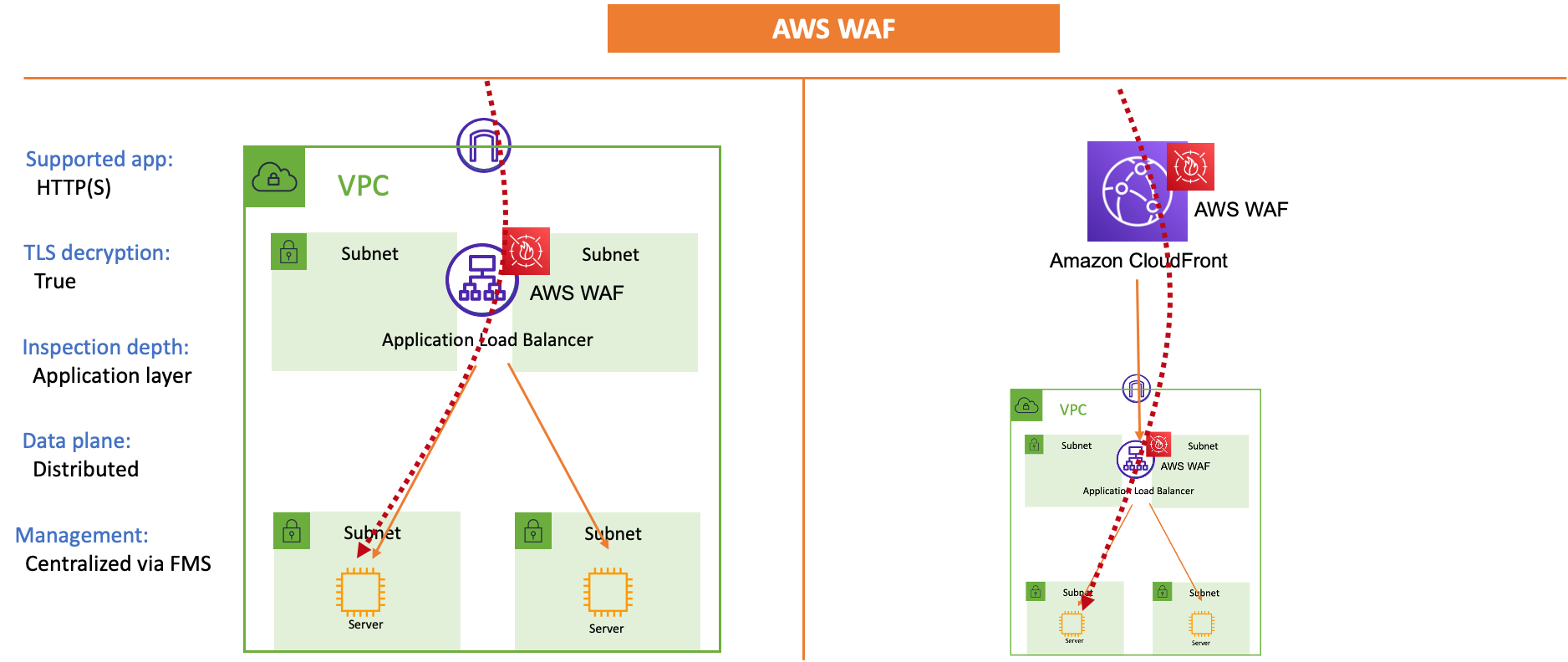
Figure 1. Distributed Deployment of AWS WAF
Directing traffic to the firewall:
AWS WAF integrates directly with Application Load Balancer (ALB), Amazon CloudFront, Amazon API Gateway, AWS AppSync (the last two not shown in the diagram). To start inspecting traffic, you need to enable the service on existing ALBs or CloudFront distributions.
Application Type and Encryption:
AWS WAF supports only HTTP/s applications. Both ALB and CloudFront terminate TLS, allowing WAF access to unencrypted traffic.
Scaling to multiple VPCs:
If you’re deploying the service across multiple VPCs, you enable WAF on each Application Load Balancer or CloudFront distribution used for your applications. You can use AWS Firewall Manager to manage and enforce policies across multiple WAF deployments centrally.
Client IP address visibility:
AWS WAF has access to the real IP address of the clients connecting to CloudFront or ALB. Note that this IP address is not preserved in the IP packet all the way to the destination backend. ALB and CloudFront would include the real client IP in the X-Forwarded-For HTTP header when forwarding traffic to the backends.
AWS Network Firewall
Figure 2. Distributed deployment of AWS Network Firewall
Directing traffic to the firewall:
AWS Network Firewall is inserted into the traffic transparently as a ‘bump-in-the-wire.’ You should deploy it in individual subnets, one per Availability Zone as AWS Network Firewall Endpoints. To get traffic inspected, you route it to the firewall endpoint using VPC subnet route tables.
To direct incoming traffic via the Network Firewall endpoint, you must configure an Ingress Route on the IGW. It will redirect traffic destined to the ELB subnets via the appropriate firewall endpoint in the respective Availability Zone. To learn more about ingress routing, you can check out this blog post.
Application Type and Encryption:
AWS Network Firewall can handle inspection of any type of traffic, not just HTTP or HTTPs, and has the ability to inspect even TLS encrypted flows. You can learn more about TLS decryption options in AWS Network Firewall documentation.
Even if you decide to not decrypt traffic, AWS Network Firewall can apply some controls beyond just the network and transport layers. It can look at the Server Name Indication extension of TLS protocol, it can enforce TLS version as well as TLS fingerprinting.
Scaling to multiple VPCs:
In the distributed model, for each VPC, you will need to deploy a separate AWS Network Firewall. Make sure you consider the cost of that deployment. You can review Network Firewall pricing here.
AWS Firewall Manager Service allows you to manage distributed Network Firewalls across hundreds of Accounts and VPCs from a single place.
Client IP address visibility:
If you deploy Network Firewall between the ELB and IGW (as shown in figure 2), it will have visibility of the real client IP addresses.
With a recent launch of more specific routing, deploying Network Firewall between the ALB (Network Load Balancer with instance target is not supported) and the backend servers is also possible. However, the firewall wouldn’t see the real client IP in the incoming packet in that architecture.
AWS Gateway Load Balancer

Figure 3. Distributed deployment of Gateway Load Balancer
Directing traffic to the firewall:
Like AWS Network Firewall, Gateway Load Balancer (GWLB) Endpoints are inserted into the traffic transparently as a ‘bump-in-the-wire’ using VPC Subnet routing and an IGW Ingress Route. You create GWLB Endpoints in individual subnets – one per Availability Zone. These endpoints provide a path to a separate VPC hosting GWLB and the third-party security appliances.
To inspect traffic, you route it to the appropriate GWLB Endpoint. From there, it’s transparently sent to GWLB and then third-party firewalls. Once traffic is inspected, it returns to the GLWB Endpoint to continue to the Elastic Load Balancer hosting the service. At no point in this flow is traffic proxied or any of the 5-TUPLE details (source IP, destination IP, source port, destination port, protocol) are changed.
Application Type and Encryption:
The type of traffic handled, and decryption support depends on the third-party vendor used behind GWLB. Enabling decryption can also decrease performance of an individual firewall. You should consult with respective firewall vendors to find out the details about their product capabilities.
If the firewalls are performing decryption, you must deploy the relevant certificates on them. Note that certificates generated in AWS Certificate Manager (ACM) can’t be deployed directly to the firewall. You would need to create the certificate outside of ACM and later import it. You can read more about services supported by ACM here.
Scaling to multiple VPCs:
A single GWLB can have multiple GWLB Endpoints from different VPCs associated with it. As you add more VPCs to your architecture, all you need to do is create additional GWLB Endpoints for each new VPC. Make sure you monitor the firewall capacity and scale it out if needed. This blog post details some of the best practices for GWLB deployments.
Client IP address visibility:
The same rules apply as with AWS Network Firewall. If you deploy the GWLB Endpoint between the ELB and IGW (as shown in figure 3), it will have visibility into the real client IP addresses. With a recent launch of more specific routing, deploying GWLB Endpoint between the ALB (NLB with instance target is not supported) and the backend servers is also possible. However, the firewalls wouldn’t see the real client IP address in the packet with that architecture.
ELB Sandwich
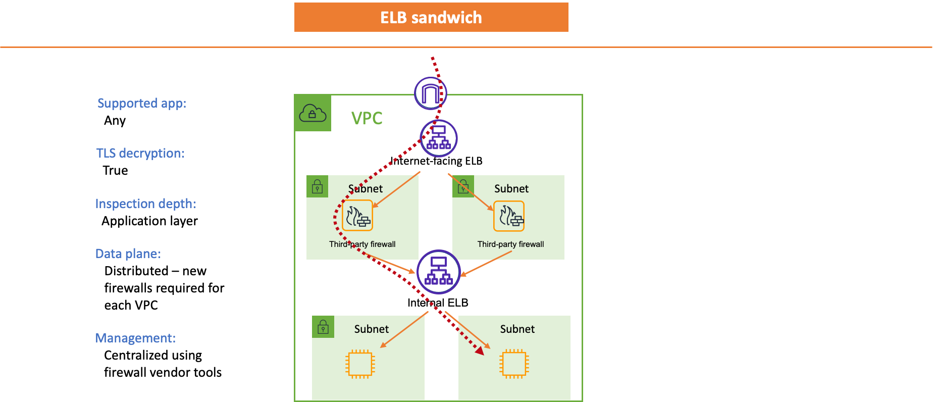
Figure 4. Distributed deployment of ELB Sandwich
Directing traffic to the firewall:
Contrary to AWS Network Firewall and Gateway Load Balancer deployments, the ELB sandwich model is not transparent. The third-party firewalls are inserted as targets of the Internet-facing ELB.
Typically, the internet-facing ELB will forward traffic to the firewalls on a specific port to differentiate between applications. For example, if you are using ALB, you could configure host-based routing to send different hostnames to the firewalls on different ports (i.e., 8081 for app1.example.com, 8082 for app2.example.com, etc.).
After the firewall inspects the traffic, it forwards it to the relevant Internal ELB.
Application Type and Encryption:
The ability to decrypt traffic will depend on the capabilities of the third-party firewall. Check with the appropriate vendor for details. Alternatively, you can forward traffic unencrypted to the firewalls once you terminate TLS on the internet-facing ELB.
Scaling to multiple VPCs:
In a distributed model, each VPC requires its own set of firewalls, which can impact the cost. Work with the firewall vendor to understand their pricing model.
From a management standpoint, make sure that the firewall vendor of your choice provides tools to manage a distributed deployment of many firewalls. Controlling a large number of firewalls with unique policies can become a challenge in larger environments.
Client IP address visibility:
The client IP preservation depends on the type of internet-facing ELB you use. NLB can preserve the client IP. This document goes into detail on what’s required to achieve that. In the case of ALB, it doesn’t preserve the client IP in the packet. The ALB adds it to an X-Forwarded-For HTTP header.
Architectures for centralized deployment
In scenarios where you can’t use distributed architectures – for example, you have a policy not allowing an IGW on your Application VPCs – you can explore a centralized architecture. Be aware, that by creating a centralized flow you are making the architecture more complex and increasing the blast radius (i.e., misconfiguration on the centralized ELBs can impact more than one backend application).
All traffic into your AWS network comes through an edge VPC hosting your security stack in this model. From there, it gets forwarded to the target application in another VPC via a Transit Gateway or PrivateLink.
When an ELB sends traffic to a remote target in another VPC, it must use IP as the target type. Both NLB and PrivateLink endpoints have static IP addresses that can be targets of any ELB.
If you host your target application on an ALB, its IP addresses can change. To get a static IP address on an ALB, you must put it behind an NLB. This blog post goes into details on that setup.
The architectures below align with the same considerations I already covered in the distributed deployment section. They expand on the previous deployments by showing how traffic from the Internet will flow if the setup is centralized.
Note that there will be performance and scaling differences between using the Transit Gateway or PrivateLink models. Refer to service-specific documentation to understand the quotas for each service you’re considering.
AWS WAF
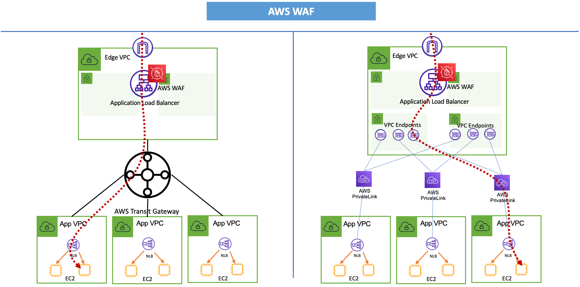
Figure 5. Centralized deployment of AWS WAF
In this model, traffic comes to an ALB running AWS WAF. It’s also possible to deploy CloudFront with WAF in front of the ALB.
ALB should target static IP addresses which could be either NLBs in the App VPCs or PrivateLink VPC Endpoints in the Edge VPC.
AWS Network Firewall
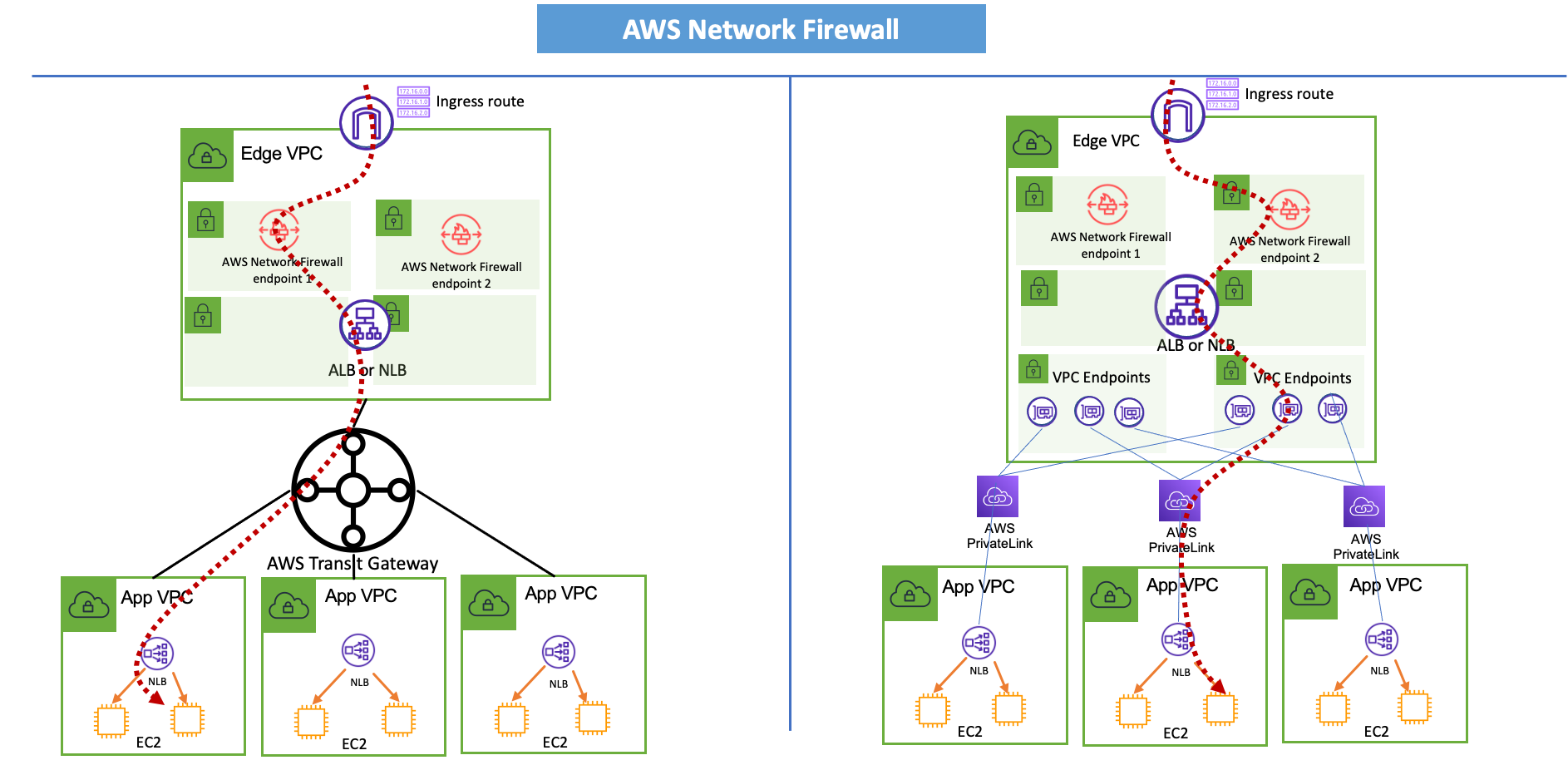
Figure 6. Centralized deployment of AWS Network Firewall
Just like with distributed model you will use an ingress route to send traffic to the firewall before it gets to an internet-facing ELB (could be ALB, NLB or even Classic Load Balancer).
AWS Gateway Load Balancer
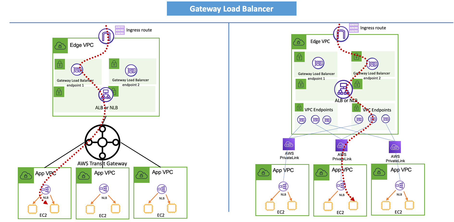
Figure 7. Centralized deployment of AWS Gateway Load Balancer
The traffic flow is exactly the same as in the Network Firewall deployment.
To simplify the drawing the VPC hosting GWLB and the third-party firewalls is not shown.
ELB Sandwich
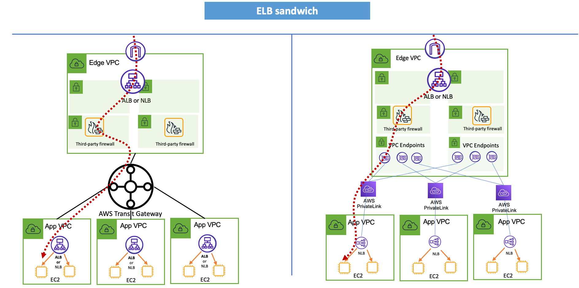
Figure 8. Centralized deployment of ELB Sandwich
The centralized ELB sandwich architecture differs from the other ones. Some third-party firewall vendors support forwarding traffic to a hostname, instead of just IP address. This means that you could send traffic from the Firewall to both ALB and NLB in remote VPCs connected via Transit Gateway.
Conclusion
The architecture patterns covered above focus on the network integration of your security components to achieve inbound filtering capabilities. When deciding on a solution, you should also consider the functionality of the firewalls and if they meet your security requirements. To follow a defense-in-depth approach, you would combine them with other AWS security services and controls such as Security Groups, NACLS, Amazon GuardDuty, Route 53 Resolver Firewall etc.

Tom Adamski
Tom is a Principal Solutions Architect specializing in Networking. He has over 15 years of experience building networks and security solutions across various industries – from telcos and ISPs to small startups. He has spent the last 4 years helping AWS customers build their network environments in the AWS Cloud. In his spare time Tom can be found hunting for waves to surf around the California coast.