AWS Storage Blog
Building a disaster recovery site on AWS for workloads on Google Cloud (Part 1)
Having a disaster recovery (DR) strategy is an essential part of business continuity and is an important part of designing your workload for resilience. Resilience means that your application, and its supporting infrastructure, always performs its intended functions correctly and consistently over time.
In some cases, customers who host their primary workloads on the cloud choose to use another cloud provider for DR. Reasons for that might be compliance, regulatory requirements, or because the organization has a mandate to adopt a multi-cloud strategy.
In this 2-part blog series, I address one use case for a sample application hosted on Google Cloud Platform (GCP) with a requirement to use AWS Cloud as a DR site. I review the steps to build connectivity between GCP and AWS, replicate a source environment (GCP) to AWS using AWS Elastic Disaster Recovery (AWS DRS), test, and failover from GCP to AWS. Finally, in part 2, I failback from AWS to GCP, to follow up the DR exercise.
Prerequisites
- You have an account on AWS and a project on GCP.
- You have Amazon Virtual Private Cloud (Amazon VPC) and a virtual private cloud on GCP with the necessary subnets.
- You have a number of VMs on GCP for testing.
- You have a dedicated subnet to host the replication server of AWS DRS.
Solution overview and walkthrough
The following diagram depicts the general architecture for the DR solution from GCP to AWS.

In part 1 of this blog series, I walk through the following:
- Configuring networking
- Configuring AWS DRS
- Performing DNS cutover
1. Configure networking
I start by building the connectivity required for the replication. After completing this part, the result will be similar to the following diagram:

Configuring networking consists of the following steps:
a. Create the networking components on GCP and AWS.
b. Establish a site-to-site VPN between GCP and on AWS.
c. Meet AWS DRS prerequisites.
a. Create the networking components on GCP and AWS
On GCP
First, I create a Cloud Router following the steps in the Cloud Router documentation. Under Network, I choose dr-vpc (created as part of the prerequisites, step 2). Under Region, I choose us-central1 (Iowa). For Google ASN, I choose 65444.

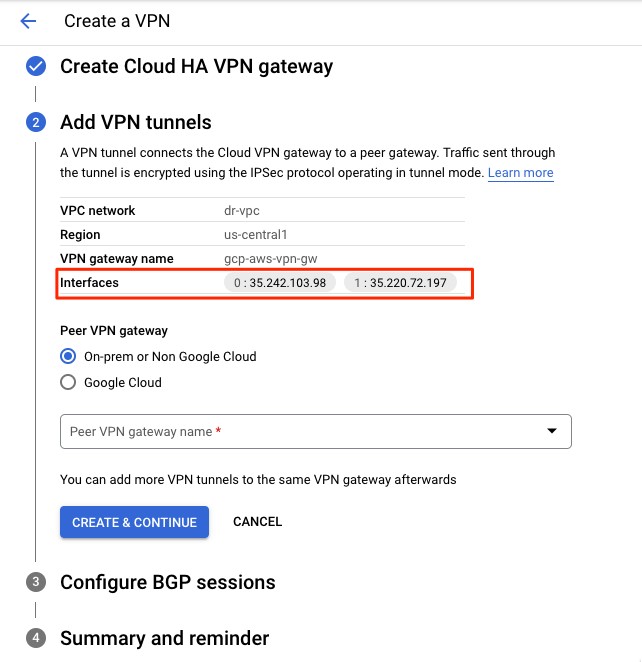
Next, I follow the guide in the Cloud Architecture Center to create a VPN connection on GCP. First, I select the type of VPN connection as high availability (HA), then I create a Cloud HA VPN gateway. I provide a name, a VPC (dr-vpc), and a Region (us-central1).

After the VPN gateway is created, it is assigned two public IP addresses. Take note of the IPs because we use them later.
On AWS
Create the following:
- Internet gateway
I create an internet gateway, and attach it to my VPC. Check steps in the Amazon VPC User Guide for instructions.

- Virtual private gateway (VGW)
I use default Amazon ASN (64512) and attach it to the Amazon VPC I created earlier. Check detailed instructions in the AWS VPN User Guide.

After I create the virtual private gateway, I attach it to my Amazon VPC.

- Customer gateway
I create two customer gateways, one for each tunnel. I provide the ASN number and the IP address in earlier steps. I repeat the same steps for the second customer gateway by providing the second IP address. I do not include the steps to configure the second tunnel here. Check steps in the AWS VPN User Guide.

After I complete the creation of the customer gateway it shows as Available.

b. Create a site-to-site VPN between AWS and GCP
Note: Before you proceed, make sure the routing tables and security configuration (for example security groups, network access lists, and firewall rules) support communications between the two VPCs on GCP and AWS.
On AWS
Now that we have the networking components up and running, I bring all the pieces together by creating a site-to-site VPN connection. In the AWS management console, under Virtual Private Network (VPN), I choose Site-to-Site VPN Connection and select Create VPN Connection. I give it a name, provide the virtual private gateway created and the customer gateway ID created earlier. For routing, I choose Dynamic, which requires Border Gateway Protocol (BGP). You can keep the rest of the configurations as default. For detailed steps, refer to Create a Site-to-Site VPN connection.
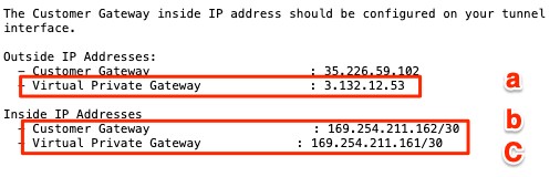
After you create the VPN connection, it creates two tunnels. The VPN connection will show Pending and the two tunnels will show that they are down at this point. You must configure the GCP side to bring them up. To do so, download the configuration file of the VPN connection you just created. Locate the lines that provide values for the following parameters for each tunnel.
- Outside IP Addresses > Virtual Private Gateway.
- Inside IP Addresses > Customer Gateway
- Inside IP Addresses > Virtual Private Gateway
I repeat the same steps for the second VPN tunnel.
On GCP
Let’s now switch to GCP. I go back to the page where I started creating the VPN connection, and I continue to create the peer configuration. I select Add a peer VPN gateway and choose two interfaces. Under Peer VPN gateway interfaces, for Interface 0 IP Address, I add the IP address of the Outside Virtual Private Gateway created earlier. For Interface 1 IP address, I provide the respective IP from AWS for the second tunnel. I will not show this part here for simplicity.
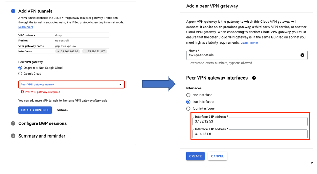
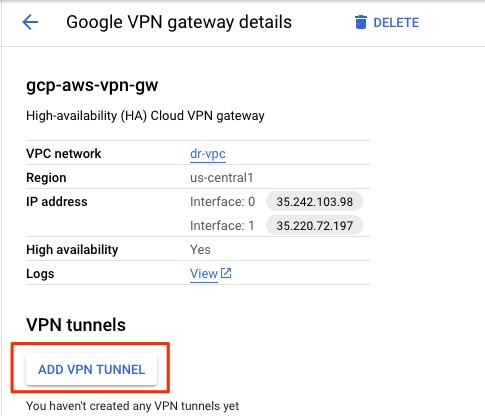
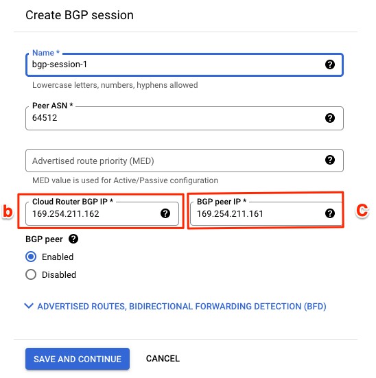
Next, I select ADD VPN TUNNEL and configure the BGP session.
I provide AWS ASN’s number (64512). In Cloud Router BGP IP and BGP Peer IP, I enter the IP from AWS.
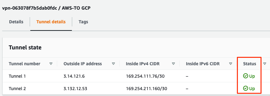
At this point, your VPN connection should show two tunnels with the status Established, and the BGP session status should be BGP established.
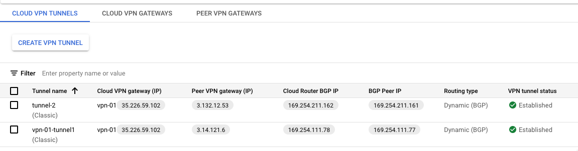
Go back to AWS and verify that the VPN tunnel is showing up as well.
c. Meet AWS DRS requirements
Before I start installing the AWS Replication Agent to replicate source servers, I must allow two required TCP ports (1500 and 443) from GCP to AWS. TCP 443 is required to connect source servers to AWS DRS endpoint, us-east-2.amazonaws.com, in this example. TCP 1500 is used for replicating data from GCP to AWS. The servers on the GCP side also must have access to Amazon Simple Storage Service (S3) URLs, which are required for downloading the AWS DRS Agent software. The following diagrams show the networking requirements. Refer to Performing a Failback for more details.
The following diagram shows the general networking requirements.

Before I start the replication, I perform a quick test to verify the connectivity. From my VM on GCP, I initiate two telnet connections to verify the connectivity. The first one is to AWS DRS endpoint on port 443, and the second one is to a server I created in the staging subnet on port 1500 on AWS. They both show that they are connected.

2. Configure AWS DRS
To configure AWS DRS, complete the following steps:
a. Create an AWS Identity and Access Management (IAM) user on AWS for AWS DRS.
b. Install AWS Replication Agent on the source environment on GCP.
c. Configure launch settings on AWS DRS.
d. Prepare for failover and then perform the failover.
a. Create an AWS Identity and Access Management (IAM) user on AWS for AWS DRS
Follow the steps in AWS Replication Agent installation instructions to create IAM credentials that AWS DRS will use to interact with your AWS account. I created a user (drs-agent-user). Take a note of the credentials created as I use them in the next step.
b. Install AWS Replication Agent on the source environment on GCP
Now you can start to install the AWS Replication Agent and start the replication to AWS. Use the following command to download the Agent and then install it on the source VM. Repeat that on each VM in the source environment on GCP.
wget -O ./aws-replication-installer-init.py
sudo python3 aws-replication-installer-init.py
The Agent installation prompts me to enter the name of the recovery Region (us-east-1), the AWS Access Key ID, and AWS Secret Access Key. The Agent uses the credentials to authenticate with AWS DRS service. If it succeeds, it creates a source server on the AWS DRS console and returns a server ID. The replication will start soon after.

c. Configure launch settings on AWS DRS
In this step, create and configure an Amazon Elastic Compute Cloud (EC2) launch template, which is required to configure the target instance we launch for a Drill/Disaster. Failure to select the right setup may cause the replication instance or the Drill/Recovery instances not to start properly on AWS, so make sure you select the right combination. Refer to the EC2 Launch Template for a full example of setting up a launch template in AWS DRS.
d. Prepare for failover and perform the failover
Once the replication has finished and is reported healthy on AWS DRS dashboard, you’re ready to start testing your recovery instances on AWS. In order to prepare for failover, you must perform continuous drills to make sure all of your network and application settings are properly configured. Performing drills is a nondisruptive operation and is a key aspect of being prepared for an outage.
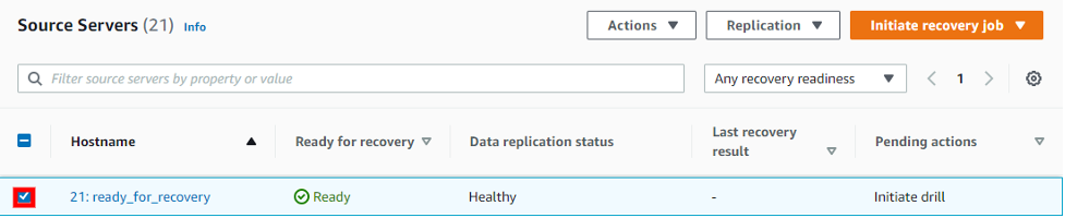
To initiate a Drill, verify that the source server shows Ready in the Ready for recovery column and Healthy under Data replication status. Then select Initiate drill from the Initiate recovery job menu.
Select the point of time that you want to recover from. AWS DRS supports going back 365 days. This number is set to 7 days by default. Note that there is increased cost when you keep the snapshot longer. For this demo, I select Use most recent data, which is a final snapshot AWS DRS takes of the source server after you initiate the recovery. This gives me a Recovery Point Objective (RPO) of seconds.

The Last recovery result column shows the status of the Recovery launch and the time of the launch. A successful Drill instance launch shows a Successful status. A launch that is still in progress shows a Pending status.

A failover is the redirection of the traffic from a primary site to a secondary site. In this case, failover is from GCP to AWS. After you verify that drill instances are working as expected, you initiate a recovery instance by selecting Initiate recovery from the Initiate recovery job menu. The steps and considerations to initiate a recovery instance are the same as in initiating a drill instance.
3. DNS cutover: Redirect user traffic from GCP to AWS.
At this point, you are still connecting to the primary site: GCP. As a last step in the failover process, switch user traffic from GCP to AWS. This is outside of AWS DRS and is typically achieved by changing the DNS record to point to the new healthy site: AWS.
The steps to change the DNS record to point to the healthy site are dependent on the DNS provider you use for the primary workload. Here are a few options to consider:
- If you use Cloud DNS as your primary Domain Name System, you must manually change the Cloud DNS zones and update the record set to point to the resource on the AWS side. (Your disaster recovery site.) This could be an Elastic Load Balancing or an EC2. At the time of writing, Cloud DNS doesn’t offer an automated way to failover.
- If you use Amazon Route 53, a scalable and highly available DNS web service, you could automate the DNS update failover process by using a combination of health checks and Route 53 DNS Failover routing policy. The failover routing directs traffic to a resource when the resource is healthy or to a different resource when the first resource is unhealthy. When creating the failover policy, you provide the resources on GCP as primary and the resources on AWS as secondary. Route 53 will take care of routing based on health checks by Route 53 Active-passive failover.
- In a combination of the DNS provider you choose, you can also use Amazon CloudFront, a content delivery network (CDN). It securely delivers static and dynamic web content with low latency and high transfer speeds using a global network of edge locations. Amazon CloudFront supports origin failover, which enables you to set up failover logic between combinations of AWS origins and non-AWS customer HTTP origins. In this case, you could set up two origins for your distributions—a primary one for your application on GCP and a secondary one on AWS. If CloudFront detects that your primary origin is unavailable based on an HTTP status code or timeout settings that you configure for failover, CloudFront will request the content from the secondary origin, AWS. Check Optimizing high availability with CloudFront origin failover for more details.
- You could, alternatively, use external products like Cloudflare Load Balancing to automatically load balance traffic between resources on GCP and AWS based on health checks. Check the How to Load Balance Site between GCP and AWS using Cloudflare blog post for an example configuration. (Note: this is an external blog post and it hasn’t been technically verified by AWS.)
Solution cost and pricing
The main components that affect your pricing in this demo are the following:
- AWS DRS: your cost is based on a flat per-hour fee for the servers that you are actively replicating to AWS. In addition to that, you must consider the cost for:
- Amazon Elastic Block Storage (EBS) volumes
- EBS snapshots
- EC2 instances for replication servers
- EC2 instances you use for drill and recovery
Refer to the AWS DRS pricing page for details.
- AWS Site-to-Site VPN: you are charged for each VPN connection-hour plus data transfer out as explained on the EC2 on-demand pricing page. In this solution, most of your traffic will be from GCP to AWS. I reverse the data direction in the next blog of this series when we discuss,which covers the failback approach. Check the AWS VPN pricing page for details.
- GCP Egress Traffic: check details on the Google Cloud VPN pricing page.
- GCP Cloud VPN: check details on the Google Cloud VPN pricing page.
- Any other service that you may choose to use.
Conclusion
Having a DR solution in place is an important part of your business continuity strategy. In this blog post, I walked you through a sample DR solution for an application hosted on GCP (primary site) with AWS as the disaster recovery site. The post showed you how to establish the networking between the two clouds using a VPN connection. It also showed how to replicate the primary servers on GCP to the recovery site on AWS using AWS DRS. I discussed the preparation for failover (setting up launch templates and performing continuous drills) and some considerations for the final cutover by changing the DNS.
In part 2 of this blog series, learn how to revert the replication back from AWS to GCP after completing a DR exercise or after the outage on the primary site is addressed. If you have any comments or questions, feel free to leave them in the comments section.