AWS HPC Blog
Conceptual design using generative AI and CFD simulations on AWS
In this post we’ll demonstrate how generative AI techniques can be combined with conventional physics-based computational fluid dynamics (CFD) simulations to create a rapid conceptual design process that can be used to explore new design concepts in the automotive, motorsport, and aerospace sectors from just a single image.
Thanks to AWS services like AWS Batch, and the open-source TwinGraph, this can all be combined into an event-driven workflow on AWS that could scale to explore millions of possible scenarios. TwinGraph is the model orchestration module within the open-source TwinFlow framework that enables deploying predictive modeling, simulation, and Level 4 Digital Twin workflows at scale.
The generative capability of machine learning (ML) algorithms holds significant promise across diverse industries. Generative AI techniques are powered by large machine learning models, pre-trained on very large amounts of data. We’re seeing the impact of these models in several areas, including transformer models for natural language processing, text-to-image models like Stable Diffusion for image manipulation, and generative adversarial networks for zero-shot classifiers.
Why is this important?
Today, an AI image generator like Stable Diffusion can be employed to generate conceptual designs for cars, planes, and other vehicles. However, these methods lack a foundation in understanding performance factors like aerodynamic drag because they don’t consider the underlying physical laws and the design constraints like noise levels and the extra energy usage they drive. In an era of increased emphasis on energy efficiency and sustainability, conceptual designs must extend beyond just adhering to style guidelines.
Over past decades, CFD-driven design optimization grew significantly across a number of industries. A general workflow typically involves simulating complex geometries using conventional physics-based solvers for different sets of individual parameters (e.g. wing chord length, or rear window angle) and finding the optimal setting across an entire parameter space.
While these solvers offer a lot of accuracy, they’re computationally intensive and time-consuming, which slows down the pace of engineering design. There’s been a growing interest in combining conventional CFD models with ML approaches to try to overcome these computational challenges. Using generative AI in the design process allows efficient sweeping of the parameter space in a non-parametric manner, based on physically meaningful design configurations of the system being examined.
We want to show you how generative AI can be applied to design optimization. In this post we’ll focus on its effectiveness in finding better solutions for drag reduction. Our approach combines generative AI for the initial design phase with OpenFOAM CFD simulations for the evaluation of vehicle aerodynamics.
Through this process, we’ve developed a workflow that empowers users to define a non-parametric design optimization problem as an algorithm suitable for execution on AWS – at scale with robust infrastructure. This is underpinned by Twingraph which does the undifferentiated heavy lifting of dynamic task orchestration, gathering provenance information, and scaling.
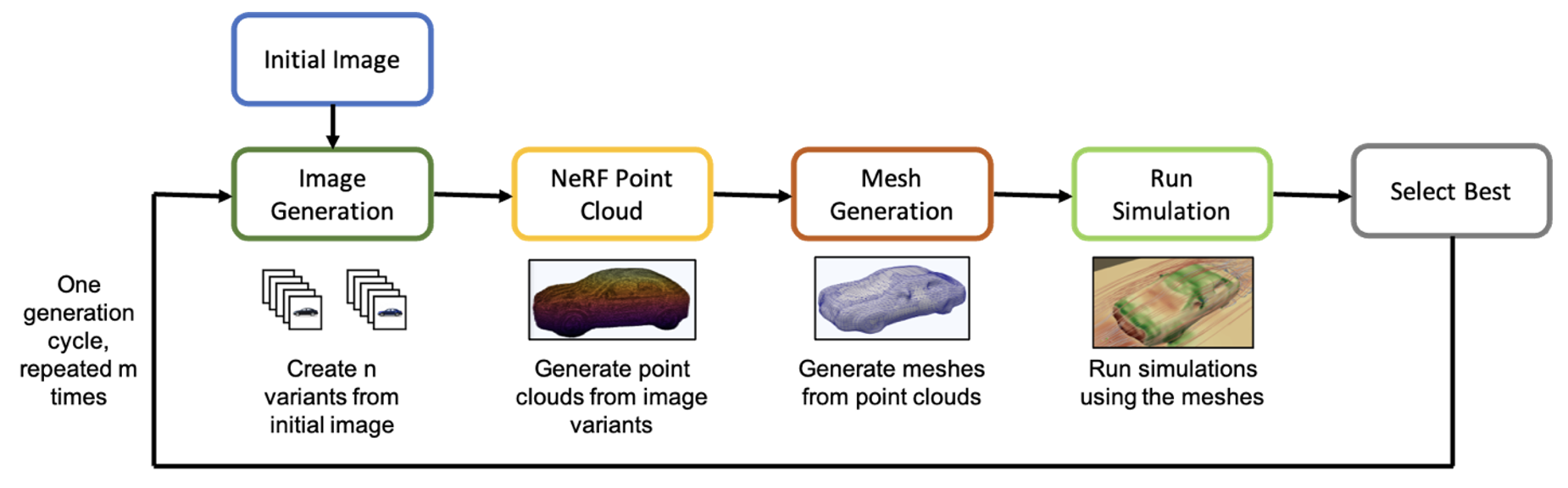
Figure 1: Overall workflow for iterative design optimization of car aerodynamics by combining Generative AI techniques and Computational Fluid Dynamics simulations
Design iterations through Stable Diffusion
Stable Diffusion is a generative AI model which enables image generation through text-driven manipulation. The underlying architecture of Stable Diffusion comprises of three key phases:
- obtaining a latent representation of the image, which captures the meaning of objects/people depicted in the image
- progressively adding Gaussian noise to this representation
- reconstructing the image through removing the noise, resulting in a modified variant of the original image which reflects the semantics of the text prompt.
As an example, in Figure 2 we show the results from using Stable Diffusion to modify an automotive design, starting from a stock image of a sedan to convert it into a sporty aerodynamic design. This resulted in a series of transformations from the original to a modified image. For this exercise, the pre-trained Stable Diffusion model was used for the image generation, but this can be fine-tuned to match the design philosophy of the individual car manufacturer.

Figure 2: Sequential transformation of a car design, given an appropriate prompt to improve aerodynamics and make the car sportier, using an image-to-image pipeline with Stable Diffusion 2.1
But this transformation isn’t based on the underlying physics – it’s an interpretation of the prompts alongside the latent space embedding, which is a condensed mathematical representation of the image, within the Stable Diffusion algorithm. In turn, this interpretation is really driven by training data that exposed the model to sports cars, leading to a predisposition for similar looking designs. To accurately evaluate if the transformation path is an improvement in the aerodynamics of the vehicle, the natural step would be to convert the image into a 3D representation that can be used for high-fidelity CFD simulations.
Generation of point-cloud using neural radiance fields
Neural radiance fields (NeRF) are algorithms showing great promise for converting one or more images into full 3D representations. Combining bootstrapped NeRF with generative adversarial networks (GANs), we can reconstruct multiple poses of objects to augment and improve the predictions.
To make this work, we feed images of the car into NeRFs to obtain signed-distance functions (SDFs) and construct point-cloud representations like we’ve shown in Figure 3. We fine-tuned the NeRF model using the Pascal3D data set for 3D object reconstruction.
Figure 3: Point-cloud of car (bottom) obtained using NeRF by using the base image (top), transforming the image into a 3D structure representing the car.
Reconstruction of surface topology from point-cloud
The point-cloud representation lacks the crucial connectivity or surface topology information that’s required for understanding the behavior of air flow around the vehicle.
To reconstruct the surface from the point-cloud, we first generated an unstructured polygonal Alpha shape mesh (for a non-convex hull). We achieved this through a coarse Delaunay triangulation using the Open3D library. This computational geometric technique identifies the encompassing surface including the points presented in the point-cloud, generated from NeRF.
To further refine the mesh, we extracted the points generated on the surface (nodes of the initial triangulation) together with estimated normals from the Alpha shapes. This surface point-cloud is ingested into a Neural Kernel Surface Reconstruction (NKSR) algorithm, which is a machine learning technique that can perform fast surface reconstructions from sparse data. The final result is displayed in Figure 4. While this technique doesn’t capture finer surface details, the overall shape of the car is approximately modeled by the resulting mesh.
Figure 4: Surface mesh generated using Neural Kernel Surface Reconstruction, with the original point cloud (top) and the triangulated mesh (bottom) showing a good match in general topographic features.
Running CFD simulations on OpenFOAM
We used OpenFoam to compute the flow field around the vehicle. We build an unstructured hex-dominate mesh with prismatic boundary layer cells using blockMesh and SnappyHexMesh from the .obj file we generated in the previous step.
For this post, we intentionally opted for much lower refinement levels than what is typically employed in the industry (we can increase these levels as required). Our mesh count was approximately one million cells, on average – this changes slightly depending on the geometry itself. To accelerate the CFD part of the process we restricted ourselves to steady-state RANS simulations using the k-omega SST model (for industrial applications you could extend this to use hybrid RANS-LES or WMLES methods, which have a higher fidelity).
Finally, in our setup we used the simpleFoam solver based upon the semi-implicit method for pressure-linked equations (SIMPLE) algorithm. Table 1 shows the parameters.
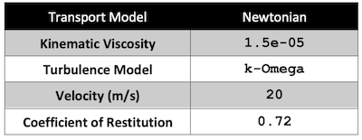
Table 1: Constants used for computational fluid dynamics simulations
The image in Figure 5 displays the streamlines as well as surface pressure over the initial car design. For this illustrative simulation, we used 425,045 cells for the mesh.
Figure 5: Streamlines visualizing flow field around a generated car mesh – these are indicative of the fluid velocities, while the colors on the car surface represent the surface pressure magnitude.
To compute the drag coefficient (Cd) values during post-processing, we derived a reference wheelbase length and frontal surface areas based on the initial designs – these reference values remain relatively constant across all observations. We used the final drag coefficient (Cd) values in the pipeline to evaluate and rank the generated design options to find the best intermediate choices.
Integration into Simulation-Guided Design Workflow on AWS
The overall workflow has five key components: image generation, Stable Diffusion, point-cloud with NeRF, mesh generation with Open3d and NKSR, and finally the OpenFoam CFD simulation. Each of these are containerized and orchestrated by the TwinGraph orchestration module within the TwinFlow framework.
We deployed this workflow by using AWS Batch and scaled it as needed to find the optimal designs. We achieved the necessary scale by leveraging both CPU and GPU architectures depending on the specific requirements of each workflow component.
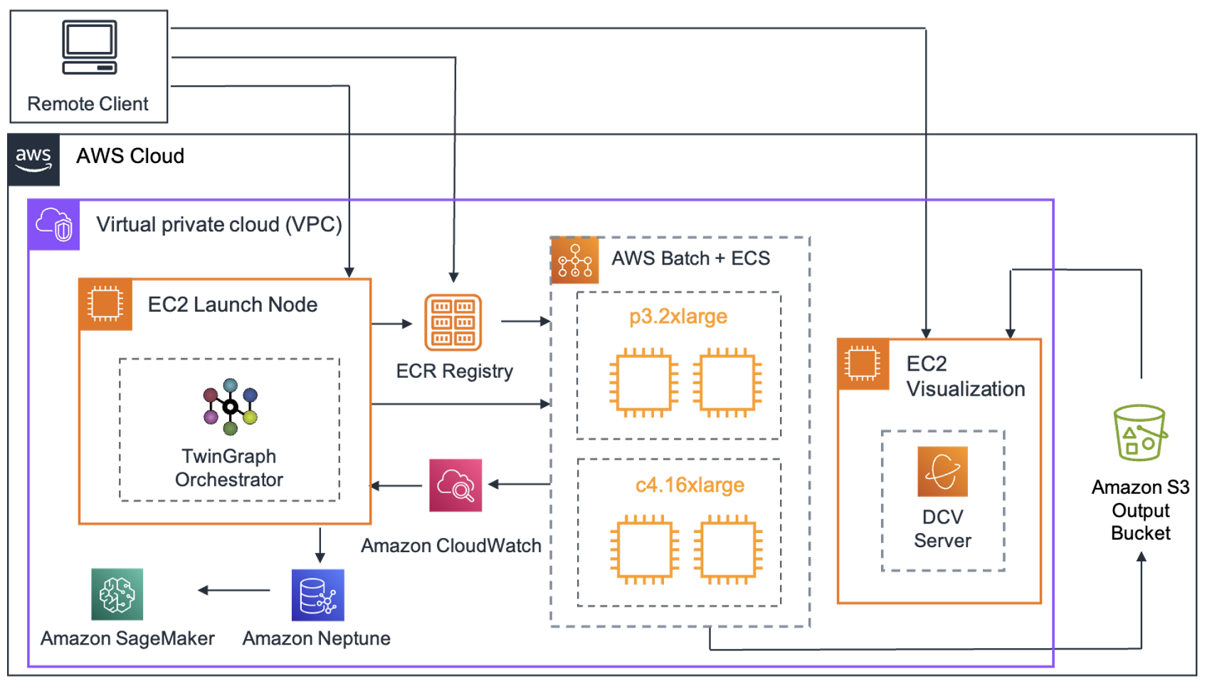
Figure 6: AWS Architecture diagram for a running workflow from connecting with a remote client, to launching the algorithmic pipeline on TwinGraph and executing jobs on AWS Batch, and visualizing results.
We repeated the experiment for a number of generated images across multiple cycles, and uploaded the results from each experiment automatically to Amazon Simple Storage Service (Amazon S3). This ensured persistent storage of our results. The necessary meta-data provenance information from each experiment was automatically uploaded to an Amazon Neptune graph database for the subsequent analysis.
Once the results were generated, we could retrieve the specific outcomes we were interested in from Amazon S3 using a GPU instance – we ran our visualization interface thought a high-performance remote desktop protocol called NICE DCV (an AWS product).
Overall, TwinGraph orchestrates tasks in an asynchronous manner, which means we can execute multiple experiments concurrently, at scale using AWS Batch.
Results
As part of the numerical experiments, we ran 10 different instances (10 variants) of the Stable Diffusion image-to-image generation, surface reconstruction, and CFD simulations with the same initialization as in Figure 1 with a generic sedan.
We used the variant image corresponding to the lowest drag coefficient (Cd) value, to seed the next image generation sequence cycle. To guide the design iteration process at a fine level, we reduced the strength of image-to-image changes significantly, compared to Figure 1.
We repeated this cycle 20 times (or 20 generations) and the results are plotted in Figure 7 as the minimum drag coefficient (Cd) per generation and in Figure 8 as a heat map of the drag coefficient (Cd) values for each of the generated designs.
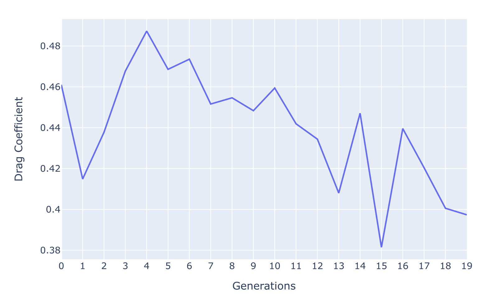
Figure 7: Minimum drag coefficients per generation, corresponding to the image variants used to create the subsequent generation of variants. The general downward trend, though non-monotonic due to intermediate car configurations, is indicative that the pipeline improves the drag performance of the best variant through the generations.
Figure 7 shows that the averaged drag coefficient (Cd) decreases gradually from an initial value of 0.46 to approximately 0.4. During the sequential generations, the decrease is non-monotonic. This is due to the non-parametric and non-linear nature of the optimization procedure – allowing the image generation process to arbitrarily morph the car design with a final goal of reducing drag.
Moreover, the intermediate design configurations have incomplete components which result in increased drag for several generations until the image generation process resolves the features. We investigated this further through drag coefficients corresponding to each variant in the 20 generations we show in Figure 8. The average drag coefficient (Cd) slightly increases in the intermediate generations but then gradually decreases towards the end of the 20 generations.
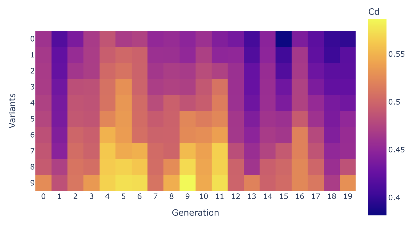
Figure 8: Illustration of drag coefficients associated with each of 10 variants (vertical axes) during each of generations (horizontal axes, sequences consisting of image generation, mesh reconstruction and simulation). The blue regions indicate lower drag, and we can observe a trend of increased blue regions going across the generations.
Figure 9: Sequence of transitions through the generations for the optimal variant in drag coefficient, demonstrating a smoothing of the hood of the car, a reduced angle of windshield.
Figure 9 provides insights into the evolution of car design across generations. The hood of the car adapts to a curved shape with considerable removal of material. Also, the angle of the windshield to the horizon reduces and there are slight changes in the curvature of the car’s rear section. Overall these are subtle, yet significant, changes driven by a generative AI process demonstrating the potential for guiding and making informed design choices through an automated physics-informed pipeline.
Limitations and future work
The approaches presented here hold promise for accelerating aesthetically and sustainability-focused non-parametric design optimization. But there are limits at each stage that will need to be overcome.
As pre-trained Stable Diffusion network weights change and evolve (due to further training), the predictions will change in an unpredictable manner – making repeatability an issue. Also, capturing surface topology and roughness accurately using this method is complex due to the lossy reconstruction from point-clouds compared to full resolution computer-aided design (CAD) meshes. This is important for accurate drag calculations.
However, with improvements in generative AI algorithms, we can expect workflows that couple machine learning to classic physics-based simulations to provide practical benefits. We can integrate multiple components into a single algorithmic pipeline that can scale agnostically with respect to the underlying infrastructure, computer architecture and choice of programming models. This provides a template to deploy future design optimization concepts across multiple domains more easily and reliably.
Conclusions
In this post, we discussed the potential for integrating generative AI techniques with physics-based CFD simulations. We demonstrated a methodology that has the capability to guide the image generation process with physics-informed drag coefficients (Cd) using CFD simulations.
We also showcased how to turn these images into 3D meshes. These meshes were used for the CFD simulations, but can also be imported into CAD programs so they can be used in real design processes.
Best of all, we combined this into a single event-driven workflow thanks to AWS Batch and TwinGraph – which allows for scaling out machine learning and simulation tasks.
This work has been focused on running inference using generative AI models, but we could use Amazon Bedrock and Amazon SageMaker JumpStart to improve the developer experience when fine-tuning the models. Amazon Bedrock is a fully managed service that provides foundation models from a collection of leading AI startups (and from Amazon itself) via an API. Bedrock allows you to speed up your development of generative AI applications that you can privately customize and scale using secure and reliable infrastructure in AWS. SageMaker Jumpstart offers you the capability to train and fine tune those foundation models in a managed environment.
This approach still requires further development to be applicable to industry, but it demonstrates the potential of integrating generative AI techniques with physics-based simulations. This potential extends beyond automotive CFD design and holds promise to a lot of other scientific and engineering fields.